1
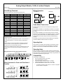
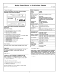
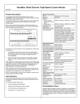
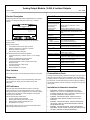
Analog Output Module, 16-Bit, 4 Isolated Outputs
October 2008
GFK-1559D
Product Description
Module Characteristics
Analog Output Module IC200ALG331 / BXIOAO4215 with 4 isolated
outputs is an intelligent module that controls to up to 4 analog
devices.
Channels
4 outputs
Module ID
Isolation:
User input to logic (optical)
and to frame ground,
Group to Group
Channel to channel
LED indicators
FFFF9805
FLD
OK PWR
ANALOG OUTPUT
VOLT/CURR ISO
16BIT
4CH
Backplane current
consumption
Configuration parameters
External power supply:
Range
Current consumption
Thermal derating
Diagnostics
In current mode, a separate power supply may be required for
isolated outputs.
Module features include:
▪
▪
▪
▪
Four isolated 4-20mA current output channels
Software configuration, no jumpers or switches
Sixteen bit converter resolution
High accuracy factory calibration
250VAC continuous; 1500VAC for 1 minute
Not applicable
250VAC continuous; 1500VAC for 1 minute
FLD PWR LED indicates the presence of both logic
power and user power. OK LED indicates module
status.
5V output: 10mA maximum.
3.3V output: 115mA maximum
Output default
+18 to +30VDC including ripple
100mA maximum plus load currents
None
High/Low Limit, Over/Underrange, Open Wire, Loss of
Field Power Supply, Non-volatile memory fault
Output Characteristics
Output operating range
Current mode: +1 to 20mA
Voltage mode: +/-10VDC
Accuracy at 25 degrees C +/- 0.1% maximum of full scale
Temperature coefficient
Current mode: 45ppm/°C typical, 90 ppm/°C maximum
Voltage mode: 30ppm/°C typical, 60 ppm/°C maximum
Current mode: 0 to 1250 ohms
Load characteristics
Voltage mode: 2K ohms minimum
Current mode: 381 nA nominal
Analog Resolution (1LSB)
Voltage mode: 381 µV nominal
Update rate
7mS maximum
Channel-to-channel
70dB minimum
crosstalk rejection
Output default
Hold Last State (default) / 0 (configurable)
The following features are software-configurable:
Per-channel selection of 4-20mA current or +/–10V voltage
outputs
▪ Selection of default/hold last state operation
▪ Per-channel selection of default values
▪ Per-channel selection of under-range and over-range
diagnostics levels
▪ Per-channel selection of alarm levels
▪ Per-channel scaling
▪ Field re-calibration on command
▪
Host Interface
Preinstallation Check
The module receives 4 words of analog output data from the system.
Carefully inspect all shipping containers for damage. If any equipment is
damaged, notify the delivery service immediately. Save the damaged
shipping container for inspection by the delivery service. After unpacking
the equipment, record all serial numbers. Save the shipping containers
and packing material in case it is necessary to transport or ship any part
Diagnostics
The module reports High/Low Limit, Over/Underrange, Open Wire,
Loss of Field Power Supply, and Non-volatile memory fault
diagnostics.
of the system.
LED Indicators
Installation in Hazardous Locations
The green FLD PWR LED indicates the presence of both logic
power and field power for the analog field-side circuits. It does not
indicate the presence of other supplies such as current loop supplies
on output points. The absence of either backplane or field power
turns off the FLD PWR LED.
The OK LED indicates module status:
▪ On green indicates normal operation.
▪ Flashing green indicates boot mode or update
▪ Flashing amber indicates self-diagnostic error.
▪ Off indicates no 3.3V power
Note that this module is the only one that has its OK LED located
before the FLD PWR LED in the A slot.
1
•
EQUIPMENT LABELED WITH REFERENCE TO CLASS I,
GROUPS A, B, C & D, DIV. 2 HAZARDOUS LOCATIONS IS
SUITABLE FOR USE IN CLASS I, DIVISION 2, GROUPS A, B, C,
D OR NON-HAZARDOUS LOCATIONS ONLY
•
WARNING - EXPLOSION HAZARD - SUBSTITUTION OF
COMPONENTS MAY IMPAIR SUITABILITY FOR CLASS I,
DIVISION 2;
•
WARNING - EXPLOSION HAZARD - WHEN IN HAZARDOUS
LOCATIONS, TURN OFF POWER BEFORE REPLACING OR
WIRING MODULES; AND
•
WARNING - EXPLOSION HAZARD - DO NOT DISCONNECT
EQUIPMENT UNLESS POWER HAS BEEN SWITCHED OFF OR
THE AREA IS KNOWN TO BE NONHAZARDOUS.
Analog Output Module, 16-Bit, 4 Isolated Outputs
October 2008
GFK-1559D
Field Wiring Terminals
Wiring Examples
Current Source
Terminal assignments for the module are shown below.
Number
Connection
Number
Connection
A1
A2
A3
A4
A5
A6
A7
A8
A9
A10
A11
A12
A13
A14
A15
A16
A17
A18
No connection
Shield Ground
No connection
Shield Ground
No connection
Shield Ground
No connection
Shield Ground
No connection
Shield Ground
No connection
Shield Ground
No connection
Shield Ground
No connection
Shield Ground
No connection
No connection
B1
B2
B3
B4
B5
B6
B7
B8
B9
B10
B11
B12
B13
B14
B15
B16
B17
B18
I1+
I1V1+
V1I2+
I2V2+
V2I3+
I3V3+
V3I4+
I4V4+
V4DC DC+
24V
Power
Supply
LOAD
3
3
4
4
V1
I1
5
5
6
6
7
7
V2
I2
AQ1
8
8
9
9
10
10
11
11
12
12
V3
I3
13
13
14
14
When a channel is configured for 4-20mA operation, the default value
should be configured within the operating range. Otherwise, if the default
value is left at zero, the module will report and under-range fault after the
configuration download or any power cycle.
16
16
17
17
18
Compatibility
18
This module is compatible with:
▪
▪
▪
▪
▪
AQ4
B
15
16
17
18
I4
13
V4
14
15
16
I3
V2
7
8
9
10
11
12
7
17
8
9
V3
10
11
AQ1
I1
1
2
3
4
5
6
1
18
AQ3
AQ2
12
AQ2
I2
V1
2
3
4
5
PLC CPU Firmware version 1.20 or later.
Ethernet NIU EBI001 all versions.
Genius NIU GBI001 Firmware version 1.10 or later*
Profibus NIU PBI001 Firmware version 1.10 or later*
DeviceNet NIU DBI001 Firmware version 2.10 or later
*
Shield Connections
14
-
Operating Notes
AQ4
13
I1-
If hot insertion of a module is done improperly, the operation of other
modules on the same backplane may be disrupted. See Installing a
Module on a Carrier in the VersaMax Modules Manual, GFK-1504.
Wiring Connections for Carriers with Three Rows of
Terminals
A
+
Operating Note
V4
I4
AQ3
AQ2
15
15
24V
Power
Supply
An Auxiliary I/O Terminal Strip can also be added to the Interposing
Terminal if additional shield connections are required.
Shield Connections
2
I1-
If the module is installed on a Connector-style I/O Carrier, the cable
shield can be connected directly to an Interposing Terminal. A shielded
interposing cable (shielded cables are available separately) must be
used between the Connector-style I/O Carrier and the Interposing
Terminal.
Wiring Connections for Carriers with Two Rows of Terminals
2
I1+
-
If the module is installed on a Terminal-style I/O Carrier or a Compact
Terminal-style I/O Carrier, the cable shield can be connected directly to
the carrier.
The loads are isolated if the loop supply is isolated. However, if the
module supply is also used as the loop supply, the loads are not
isolated.
1
-
I1+
Shielded twisted pair cable is recommended for the analog channel
connections.
Current outputs act as current regulators and require a supply to
power the load. The current loop can be connected either as a
current source or as a current sink to the load.
1
-
+
LOAD
Cable Shield Connections
Voltage outputs are powered from the module. For each channel, V+
is positive with respect to V- when the channel’s output data is
positive.
A
+
+
A 24 volt power supply must be connected to B17 and B18 to
operate the module.
B
Current Sink
6
2
For GBI001 and PBI001, NIU version 2.0 or above is required to
perform software configuration.
Analog Output Module, 16-Bit, 4 Isolated Outputs
October 2008
GFK-1559D
Diagnostics
Configurable Features
The module can detect and report the following faults:
Over-Range: The module reports an Over Range fault if an input
value is greater than approximately +12.5 volts or 25 mA.
Under-Range: The module reports an Under Range fault if an input
value is approximately 0mA on an current channel or –12.5 volts on
a voltage channel.
Open Wire: The module reports an Open Wire fault on current
inputs if the configuration of the low end of the range is greater than
or equal to approximately 2.0 mA, but the input is not detecting
current.
Loss of Field Power Supply: The module reports a Loss of Field
Power fault if field power is not present (also indicated by the FLD
PWR LED). Inputs default as specified by the configuration.
High Limit: The module reports a High Alarm fault if an input value
is greater than or equal to the value specified by the “Alarm High”
configuration parameter.
Low Limit: The module reports a Low Alarm fault if an input value
is less than or equal to the value specified by the “Alarm Low”
configuration parameter.
Non-volatile Memory Fault: The module reports this fault only
during field recalibration, if a non-volatile memory fault is detected.
The default parameters of this module can be used in many
applications. The module can be software-configured when it is installed
in a PLC system, or an I/O Station controlled by a Network Interface Unit
that supports software configuration, as listed above.
The module is configured at startup. After configuration, the module
begins providing signals from the voltage or current output devices
connected to it to the CPU or NIU.
Parameter Description
Analog
Input Data
Reference
Analog
Input Data
Length
Line
Frequency
Report
Faults
%AI Default /
Hold Last
State
Calibration
Default
Choices
user selectable
Starting offset for the module’s
analog input data.
8
0–8
Specifies the line filter frequency.
60 Hz
50 Hz, 60 Hz
Enables or disables Fault Reporting
for the entire Module.
Enabled
Enabled,
Disabled
Specifies whether the module will
go to the specified channel defaults
(see below) or hold their last states
if power or communications are
lost.
Default
Default /Hold
Word length of the module’s
analog input data.
The module is calibrated at the factory. For most applications, no
further calibration is required. It is possible to perform recalibration in
either of the following ways:
▪ By changing a module’s scaling so its scaled data agrees with
metered values.
▪ By sending the module a recalibration message as described in
the PLC User's Manual. Note that the module must be power
cycled when reverting from field calibration back to factory
calibration.
Current /
Voltage
Specifies whether the channel will
be a voltage or current input.
If the Channel type is Current, the
range is 4 to 20mA.
If Channel type is Voltage, the
range is –10 to +10V.
I (Current)
I (Current),
V (Voltage)
Channel
Active
Specifies if the channel should
input data received from the CPU
or NIU. If a channel is “inactive”
space is still allocated for it.
Active
Inactive (off),
Active (on)
Output Defaults
Span Low Actual current (in microAmps) or
voltage (in milliVolts) to be scaled
from low engineering units value.
4,000 µA
Span High Actual current in microAmps or
voltage in millivolts to be scaled
from the high engineering units
value.
Engineering The engineering units value that is
Low
considered equivalent to the low
span (actual) value.
20,000 µA
0 to 25,000 µA
–10,000 to
+10,000mV
0 to 25,000 µA
–10,000 to
+10,000mV
Engineering The engineering units value that is
High
considered equivalent to the high
span (actual) value.
Alarm Low The low alarm limit for the channel,
in engineering units.
20000
4000
-32768 to +32767
Alarm High The high alarm limit for the channel,
in engineering units.
20000
-32768 to +32767
0
-32768 to +32767
The module requires both logic and module 24 volt power supplies
to produce an output. Subsequent loss of power or communication
will produce output states as determined by the configuration. These
are:
Power and Configuration states
Field power, no logic power, not
configured
Field and logic power, not configured
Field and logic power, configured
Module defaults due to loss of
communications or other cause.
Loss of backplane power after
configuration
Communication returns without loss of
Field Power
Output Condition
All outputs 0
All outputs 0
Outputs are scaled and follow program
data
Outputs are set to configured default:
value or Hold Last State.
In I/O Station with NIU, outputs are set
to 0.
Outputs are set to Hold Last State if
configured for Hold Last State operation,
or to 0 if “default” was configured. A
configured default value is not available
to the module if backplane power has
been lost.
In I/O Station with NIU, outputs set to 0.
Outputs resume operation after
configuration.
Default
3
The value to be input when the
module is in a default condition.
4000
0 to 25,000 µA
–10,000 to
+10,000mV
0 to 25,000 µA
–10,000 to
+10,000mV
Analog Output Module, 16-Bit, 4 Isolated Outputs
October 2008
GFK-1559D
Description of Configurable Features
Scaling Values for 1mV or 1µA Engineering Units
Channel Active: Each channel can be configured as either active or
inactive. If a channel is inactive, it is not scanned and a value of 0 is
returned by the module.
For many applications, the engineering units are either millivolts or
microAmps. These units are easy to scale. Simply use the table below to
find scaling values that are appropriate for the channel’s configured
range.
Low Alarm Limit and High Alarm Limit: Each input channel can
have a low alarm limit and a high alarm limit. If an input reaches
one of its limits, the module reports the actual value and sends the
appropriate diagnostic input bit. Alarms do not stop the process or
change the value of the input.
Alarm limits can be set anywhere over the dynamic range of the
signal. The range for each is –32,768 to +32,767. The high alarm
limit must be greater than the low alarm limit. If alarm reporting is
not wanted, alarm limits can be set beyond the dynamic range of the
signal so they will never be activated.
Scaling: The module converts electrical signals (either current or
voltage, as configured) into digital output values for the CPU or NIU.
By default, the module converts this data from 1 millivolt or 1
microamp “internal units” for convenience in scaling and comparing
to actual meter measurements.
Examples
Output
Range
Enter this
engineering
units value
Span Units
(microAmps)
4 mA to 20 mA
4 mA
20 mA
Low
High
+4,000
+20,000
Low
High
+4,000
+20,000
-10 volts to +10
volts
0 volts
+10 volts
Low
High
0
+10,000
Low
High
+4,000
+20,000
0 mA to 20 mA
0 mA
20 mA
Low
High
0
+20,000
Low
High
0
+20,000
-10 volts to +10
volts
-5 volts
+10 volts
Low
High
-5,000
+10,000
Low
High
-5,000
+10,000
Product Version Information
The module’s default scaling can be changed to tailor the data for a
specific application. Typically, engineering units represent millivolts
or microamps. But they may also represent physical units such as
degrees or centimeters per second. When reconfiguring scaling, it is
important to be sure that the chosen Engineering Units values would
not result in Overrange or Underrange output levels.
Rev
IC200ALG331-FB
BXIOAO4215-FB
IC200ALG331-EB
BXIOAO4215-EB
The scaling for each channel can be configured independently.
Scaling is configured by selecting corresponding low and high
engineering units values and low and high span values for two
points.
IC200ALG331-DB
BXIOAO4215-DB
IC200ALG331-DA
BXIOAO4215-DA
During operation, the module will use the straight line defined by
these two pairs of configured scaling values to convert internal
values to current or voltage signal levels that represent appropriate
engineering units.
IC200ALG331-BA
BXIOAO4215-CA
IC200ALG331-AA
BXIOAO4215-AA
Fault Reporting: By default, the module is configured for fault
reporting. The module reports faults as soon as they are detected.
Once a fault has been reported, the same fault is not reported again
until the fault has been cleared. Fault reporting can be disabled via
configuration. If disabled, faults are not reported.
Configuring Scaling
The module converts digital output values received from the CPU or
NIU to electrical signals (either current or voltage, as configured). By
default, the module converts this data to 1 millivolt or 1 microamp
“internal units” for convenience in scaling and comparing to actual
meter measurements.
The module’s default scaling can be changed to tailor the output
data to a specific application. Typically, engineering units represent
millivolts or microamps. But they may also represent physical units
such as degrees or centimeters per second. When reconfiguring
scaling, it is important to be sure that the chosen Engineering Units
values would not result in Overrange or Underrange output levels.
The scaling for each channel can be configured independently.
Scaling is configured by selecting corresponding low and high
engineering units values and low and high internal values (counts)
for two points.
During operation, the module will use the straight line defined by
these two pairs of configured scaling values to convert internal
values to current or voltage signal levels that represent appropriate
engineering units.
4
Date
Description
October 2008 Updated Power Supply OK signal
circuitry.
July 2005
Improvement to latching
mechanism
February 2005 Firmware revision 1.10. Fault
reporting for active channels only.
April 2004
Changed to V0 plastic for module
housing.
January 2004 ATEX approval for Group 2
Category 3 applications.
July 1999
Initial product release