1
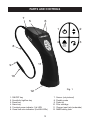
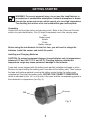
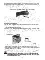
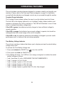
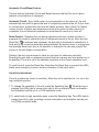
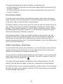
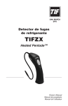
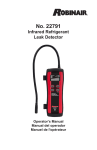
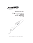
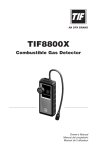
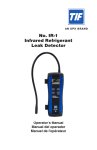
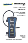
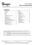
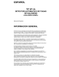
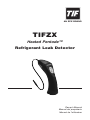
an spx brand
TIFZX
Heated Pentode™
Refrigerant Leak Detector
Owner’s Manual
Manual del propietario
Manuel de l’utilisateur
table of contents
General Description . . . . . . . . . . . . . . . . . . . . . . . . . . . . . . . . . . 2
Features . . . . . . . . . . . . . . . . . . . . . . . . . . . . . . . . . . . . . . . . . . . . 2
Parts & Controls . . . . . . . . . . . . . . . . . . . . . . . . . . . . . . . . . . . . . 3
Getting Started
Unpacking . . . . . . . . . . . . . . . . . . . . . . . . . . . . . . . . . . . . . . . . . . . 4
Installing and Charging Batteries . . . . . . . . . . . . . . . . . . . . . . . . . 4
Sensor and Probe Installation . . . . . . . . . . . . . . . . . . . . . . . . . . . . 5
Operating Features
Constant Power Indication . . . . . . . . . . . . . . . . . . . . . . . . . . . . . .
True Battery Voltage Indicator . . . . . . . . . . . . . . . . . . . . . . . . . . . .
Automatic Circuit / Reset Feature . . . . . . . . . . . . . . . . . . . . . . . . .
Sensitivity Adjustment . . . . . . . . . . . . . . . . . . . . . . . . . . . . . . . . . .
Sensor Status Indicator . . . . . . . . . . . . . . . . . . . . . . . . . . . . . . . . .
Audible / Visual Alarms – Mute Feature . . . . . . . . . . . . . . . . . . . .
6
6
7
7
8
8
Operation . . . . . . . . . . . . . . . . . . . . . . . . . . . . . . . . . . . . . . . . . . . 9
Operating Tips . . . . . . . . . . . . . . . . . . . . . . . . . . . . . . . . . . . . . . 10
Maintenance
Battery . . . . . . . . . . . . . . . . . . . . . . . . . . . . . . . . . . . . . . . . . . . . .
Sensor . . . . . . . . . . . . . . . . . . . . . . . . . . . . . . . . . . . . . . . . . . . . .
Probe Tip and Filter . . . . . . . . . . . . . . . . . . . . . . . . . . . . . . . . . . .
General Care . . . . . . . . . . . . . . . . . . . . . . . . . . . . . . . . . . . . . . . .
12
13
15
16
Specifications . . . . . . . . . . . . . . . . . . . . . . . . . . . . . . . . . . . . .
Replacement Parts . . . . . . . . . . . . . . . . . . . . . . . . . . . . . . . . . .
Warranty . . . . . . . . . . . . . . . . . . . . . . . . . . . . . . . . . . . . . . . . . . .
Troubleshooting . . . . . . . . . . . . . . . . . . . . . . . . . . . . . . . . . . . .
17
18
19
20
1
general description
Thank you for purchasing the TIFZX Heated Pentode™ Refrigerant Leak Detector. We are
proud to offer what we believe is the very best portable electronic leak detector available today.
TIFZX offers the greatest sensitivity and fastest response of any portable refrigerant detector
available. This is achieved through the employment of a Heated Pentode™ sensor combined
with a sophisticated microprocessor-controlled circuit.
In addition to the supreme performance and functional advantages, TIFZX offers a leading edge,
unique, and ergonomically designed shape to provide greater ease of use, comfort, and of
course, appearance.
In order to gain the fullest benefits of your purchase, please carefully read and review the
information in the following pages. If you have further questions, or need additional assistance,
please contact your distributor.
features
•
•
•
•
•
•
•
•
•
•
•
•
•
•
Heated Pentode™ sensor technology
Detects ALL halogenated refrigerants at levels below 0.1 oz/yr
Tri-color, visual, leak size indicator
Tactile keypad controls with one-touch reset and adjustable sensitivity
True mechanical pump provides instant response and clearing
Battery test function
Sensor failure indication
NiMH rechargeable batteries
Revolutionary design
Meets SAE J1627
Flexible stainless probe
Carrying pouch and recharger included
CE approved
3-year warranty
2
parts and controls
7
6
5
8
1
2
4
3
11
9
10
Fig. 1
12
1. On/Off key
2. Sensitivity high/low key
3. Reset key
4. Alarm key
5. Constant power indicator (1st LED)
6. Visual leak size indicators (2nd-6th LEDs)
3
7. Sensor (not pictured)
8. Flexible probe
9. Probe tip
10. Filter cartridge
11. Charger input jack (underside)
12. NiMH battery pack
getting started
WARNING: To prevent personal injury, do not use this Leak Detector in
an explosive or combustible atmosphere. Ambient atmosphere is drawn
through the probe and sensor, which operate at a very high temperature.
The resulting hot mixture of air and combustible gas could explode.
Unpacking
Unpack the unit from the carton and carrying pouch. Refer to the Parts and Controls
section for parts identification. Five (5) major components are in the carrying case:
Unit
Battery pack
Sensor
Probe
Battery charger
Before using the leak detector for the first time, you will need to charge the
batteries, install the sensor, and install the probe.
Installing and Charging Batteries
CAUTION: To prevent equipment damage, charge batteries only in temperatures
between 50°F and 104°F (10°C and 40°C). Charging batteries outside this
temperature range may cause permanent damage to the batteries.
A new unit comes shipped with the battery pack partially installed and taped in place.
Remove the tape holding the battery pack, and remove the battery pack. Then remove
the tape and packing material covering the battery socket inside the battery pack
compartment. Re-insert the battery pack, noting the correct orientation,
which is indicated by the “rib” on one side of the pack and the corresponding groove in
the instrument’s compartment (see Fig. 2).
Groove
Rib
Fig. 2
44
Once the battery pack has been installed, plug the battery charger into a wall outlet
and connect the charger jack to the unit (see Fig. 3). When correctly connected, the
first LED will indicate charging status:
Quickly flashing orange = battery charging
Slowly flashing green = battery fully charged
Slowly flashing red = failed batteries; cannot be recharged
Fig. 3
New or completely discharged batteries will take approximately two (2) hours to fully
recharge. When the LED indicates the batteries are fully charged, the unit is ready for
operation.
Sensor and Probe Installation
A new unit comes shipped with the probe not installed on the unit, and the sensor
packaged in a sealed foil bag.
1. Open the bag and remove the sensor.
2. Hold the unit with the front end facing you and note the sensor connection inside
the threaded bushing on the end of the unit. There are five (5) holes corresponding
to the five (5) pins on the sensor – three (3) on the left and two (2) on the right
(refer to Fig. 4).
Threaded Bushing
Pins
Sensor
Fig. 4
3. Align the pins in the sensor with the corresponding holes in the threaded bushing.
When correctly aligned, firmly push the sensor into the bushing until it stops.
4. Install the flexible probe by threading it clockwise onto the threaded brass bushing
around the sensor until it is finger tight.
CAUTION: To prevent personal injury and equipment damage, NEVER
operate the unit without the flexible probe correctly installed. Sensor
contamination, erratic performance, and other problems may occur.
Additionally, the sensor will become quite hot during operation, which
could cause personal injury.
5
operating features
This unit includes operating features designed to increase usability and simplify user
interface. Please refer to the Parts and Controls diagram on page 3 to familiarize
yourself with the indicators and keypad controls as you proceed through this section.
Constant Power Indication
The Constant Power indicator allows the user to see the battery level at all times.
The first LED in the display (leftmost) is an “intelligent” battery status indicator and
remains on whenever the unit is powered on. The LED will illuminate in one of three
colors to indicate the battery voltage level.
If the LED is green, the batteries are fully charged or have sufficient voltage for
normal operation.
If the LED is orange, the batteries have enough voltage to operate, but should be
recharged when the current usage of the unit is complete.
If the LED is red, the batteries should be immediately recharged to prevent erratic
performance and / or failure of the unit during operation.
True Battery Voltage Indicator
The unit also includes a feature that allows you to display and see the actual battery
voltage at any time.
To activate the True Battery Voltage test,
1.Press and release the ON/OFF key
to turn the unit ON.
2.Then press and hold the ON/OFF key.
3.The display will show 1 to 6 LEDs in red, orange, and green to indicate the actual
battery voltage as follows:
•
•
•
•
•
•
1 red = less than 4.4 volts—RECHARGE THE UNIT IMMEDIATELY
1 red, 1 orange = 4.4 to 4.6 volts
1 red, 1 orange, 1 green = 4.6 to 4.8 volts
1 red, 1 orange, 2 green = 4.8 to 5.0 volts
1 red, 1 orange, 3 green = 5.0 to 5.2 volts
1 red, 1 orange, 4 green = greater than 5.2 volts; fully charged
6
Automatic Circuit/Reset Feature
The unit features Automatic Circuit and Reset functions that set the unit to ignore
ambient concentrations of refrigerant.
Automatic Circuit - Upon initial power-on and completion of the warm-up, the unit
automatically sets itself to ignore the level of refrigerant present at the tip. Only a level,
or concentration, greater than this level will cause an alarm. Note: Since this feature
causes the unit to ignore any refrigerant present at the probe tip after warm-up is
completed, the unit should be powered on and allowed to warm up in fresh air.
Reset Feature - Resetting the unit during operation performs a similar function; it
programs the circuit to ignore the level of refrigerant present at the tip. Each time the
Reset Key
is pressed (and released), the unit sets its threshold for detection to a
level above the current concentration being detected. By moving closer to a large leak,
and pressing Reset each time a full detection is indicated, the user can pinpoint the
source of the leak (higher concentration).
Similarly, the unit can be moved to fresh air and reset for maximum sensitivity.
Resetting the unit with no refrigerant present (fresh air) causes any level above zero to
be detected. The unit is set to its maximum sensitivity in the chosen sensitivity level.
To reset the unit, press the Reset Key. Each time the Reset Key is pressed, the LEDs
briefly show orange to provide a visual confirmation of the reset action.
Sensitivity Adjustment
The unit provides two levels of sensitivity. When the unit is switched on, it is set to the
high sensitivity position.
1. To change the sensitivity of the unit, press the Sensitivity Key . When the key is
pressed, the LEDs light in orange from right to left, providing a visual confirmation
and indication that the unit is in Low sensitivity mode.
2. To switch back to high sensitivity again, press the Sensitivity Key. The LEDs light in
orange from left to right, providing a visual confirmation and indication that the unit
is in High sensitivity mode.
7
The standard beeping tone is also an indication of sensitivity level.
- In High sensitivity the unit emits two quick beeps approximately once every two (2)
seconds, in fresh air.
- In Low sensitivity the unit emits only one beep, approximately once every two (2)
seconds, in fresh air.
Sensor Status Indicator
The unit’s circuit has the ability to automatically diagnose and indicate the sensor’s
status. Whenever the unit is energized, the circuit automatically senses the condition
of the sensor and can detect a failed or missing sensor.
Old Sensor Indication: As the sensor ages, the circuit will note and indicate this to the
user. Initially, an Old Sensor Indication is displayed by flashing the Constant Power
Indicator. If this indication appears, it is time to obtain a replacement sensor. Refer to
the Replacement Parts section. However, it is not necessary to replace the sensor
before the Failed Sensor Indication is received.
Failed Sensor Indication: If the circuit detects a failed or missing sensor, the 2nd
through 6th LEDs turn red and flash quickly. The 1st LED continues to display the
battery status as described earlier. Additionally, the internal pump shuts down to
prevent unnecessary battery drain. If this indication appears, refer to the Maintenance
section for service instructions.
Audible / Visual Alarms – Mute Feature
The unit features two primary alarm indications – an internal speaker that produces a
multiple frequency tone, and a series of tri-color LEDs that provide an incremental
indication of leak detection and proportional leak size.
You may choose to activate both the audible and visual alarms, or use only the visual
alarm. Upon power-on, the unit will activate both. If you wish to cancel or “mute” the
audible alarm, press the Alarm Key
.
This mutes the internal speaker, and detection will be indicated solely by the LED
display. Press the Alarm Key again, at any time, to reactivate the internal speaker.
The LEDs provide a tri-color, proportional indication of leak intensity. The 2nd through
6th LEDs are used for this indication, while the 1st LED always remains an indication
of battery strength. See Figure 5.
8
Constant
Power
Indicator
(1st LED)
Proportional
indicators
(2nd – 6th LEDs)
Figure 5
When a refrigerant is detected, the visual indicator lights from left to right; first in
green, then sequentially in orange, and then sequentially in red. Often, on anything but
the smallest leak, the extreme sensitivity of the unit may cause the LEDs to all light in
orange or red. Since each LED can appear in one of three colors – green, orange or
red – this will result in 15 distinct alarm levels.
OPERATION
WARNING: To prevent personal injury, do not use this Leak Detector in
an explosive or combustible atmosphere. Ambient atmosphere is drawn
through the probe and sensor, which operate at a very high temperature.
The resulting hot mixture of air and combustible gas could explode.
1.Press and release the ON/OFF Key to switch the unit on.
2.The LEDs begin cycling in orange, from left to right, to indicate warm-up. The warmup time is fixed at 20 seconds.
3.After warm-up, all LEDs briefly flash orange, indicating the unit is ready for use. The
unit begins beeping at a steady rate (two quick beeps approximately once every two
seconds – indicating high sensitivity). The first LED displays the battery voltage
level as described in the Constant Power Indicator section.
4.Set the sensitivity level you wish to use, as described in the Sensitivity Adjustment
section.
9
5. Begin searching for leaks. Move the probe tip toward the suspected leak. The
flexible probe may be shaped to provide access to hard-to-reach areas.
NOTE: If the unit has previously been in service, verify the probe tip is not
obstructed with dirt, grease, etc., and check the condition of the filter as described
in the Maintenance section.
6. If a refrigerant is detected, the unit will begin to alarm – the audible tone will quicken
and the LEDs will light. The larger the detected concentration, the greater the alarm.
The LEDs provide a proportional indication of concentration:
• Green – small concentration
• Orange – moderate concentration
• Red – large concentration
NOTE: The unit is not a measuring tool; it is a proportional detector. The LEDs do not
indicate a specific leak rate or concentration.
7. If an alarm occurs before the leak source is pinpointed, the Reset Key may be used
to pinpoint the leak, as described in the Operating Features section. The unit may
be reset as many times as necessary to pinpoint the leak source.
NOTE: Due to the high sensitivity of the instrument, it is possible it will detect the
presence of high intensity electromagnetic fields.
OPERATING TIPS
The following section includes several general operating tips, and the SAE J1628
recommended procedure for leak detection.
LEAK DETECTION TECHNIQUES
1. Before each use, inspect the probe tip and filter element as described in the
Maintenance section.
2. Be aware that refrigerants are invariably heavier than air and will tend to fall from,
or collect below, actual leak points/sources. Searching below areas of potential
leaks is the most effective and reliable method of detection.
3. In areas that are heavily contaminated with refrigerant, the unit may be reset to
block out ambient concentrations of gas. The probe should not be moved while the
unit is being reset. The unit may be reset as many times as needed.
10
4.In windy areas, even a large leak can be difficult to find. Under these conditions, it is
best to shield the potential leak area from wind or breezes.
5.A leak is a constant source of refrigerant, and when a true leak source is located, it
should produce a repeatable alarm each time it is approached. Intermittent (nonrepeatable) alarms are often caused by accumulations of refrigerant near or around
leak points.
6.If an alarm occurs, and cannot be repeated when the probe tip is placed at the
same point again, it is unlikely there is a significant leak present at that point.
However, this may be indicative of a leak nearby – and can be used as a diagnostic
aid in leak finding.
SAE J1628 Recommended Procedure
NOTE: Leak test automotive A/C systems with the engine turned OFF.
1. The air conditioning or refrigeration system should be charged with sufficient
refrigerant to have gauge pressure of at least 340 kPa (50 psi) when not in
operation. At temperature below 15°C (59°F), leaks may not be measurable, since
this pressure may not be reached.
2. Do not contaminate the detector probe tip nor part being tested. If the part is
particularly dirty, or condensation (moisture) is present, clean it with a dry shop
towel or shop air. Do not use cleaners or solvents, since the detector may be
sensitive to their ingredients.
3. Visually trace the entire refrigerant system, and look for signs of air conditioning
lubricant leakage, damage, and corrosion on all lines, hoses, and components.
Check each questionable area with the detector probe, as well as fittings, hose-toline couplings, refrigerant controls, service ports with caps in place, brazed or
welded areas, areas around attachment points, and hold-downs on lines and
components.
4. Follow the refrigerant system around in a continuous path so no areas of potential
leaks are missed. If a leak is found, continue to test the remainder of the system.
5. At each area checked, move the probe around the location at a rate no more than
25 to 50 mm/second (1–2 inch/second), and no more than 5 mm (1/4 in.) from the
surface, and completely around the position. Slower and closer movement of the
probe greatly improves the likelihood of finding a leak (see Fig. 6). Any increase in
the alarm rate is indicative of a leak.
Fig. 6
11
6. Verify an apparent leak as follows:
a) Blow shop air into the area of the suspected leak. Repeat the check of the area. In
cases of very large leaks, blowing out the area with shop air often helps locate the
exact position of the leak.
b) Move the probe to fresh air and reset. Then hold the probe tip as close as possible
to the indicated leak source, and slowly move around it until the leak is confirmed.
Automotive A/C Systems Only
7. Leak test the evaporator core in the air conditioning module by turning the air
conditioning blower on high for a period of 15 seconds minimum, shutting it off, and
then waiting for 10 minutes for the refrigerant to accumulate in the case.
Then insert the leak detector probe into the blower resistor block or condensation
drain hole, if no water is present, or into the closest opening in the heating/
ventilation air conditioning case to the evaporator, such as the heater or vent duct. If
the detector alarms, a leak apparently has been found.
MAINTENANCE
BATTERY MAINTENANCE
The unit is equipped with a standard nickel–metal–hydride (Ni-MH) battery pack. Refer
to the Replacement Parts section for details.
Charging Batteries
CAUTION: Charge batteries in temperatures ranging between 50°F and 104°F
(10°C - 40°C). Charging batteries outside this temperature range may cause
permanent damage to the batteries.
Whenever the Constant Power Indicator LED appears red, and/or the True Battery
Voltage test shows only the red LED, the batteries must be recharged.
To recharge the batteries:
1. Plug the charging unit into an appropriate wall outlet, and connect the charger jack
to the unit (see Fig. 3, page 5).
12
2.When correctly connected, the first LED indicates the charging status:
- Quickly flashing orange = battery charging
- Slowly flashing green = battery fully charged
- Slowly flashing red = batteries failed; cannot be recharged
New or completely discharged batteries take approximately two (2) hours to fully
recharge.
3. When the LED indicates the batteries are fully charged (slowly flashing green), the
unit is ready for operation.
NOTE: When the unit is not in use, it should be connected to the charger to ensure full
battery power is later available. The internal charging circuit prevents over-charging
and provides a continuous maintenance charge when required by the batteries.
Storage
Even when powered off, the unit slowly discharges the batteries over time. Before
storing the unit for extended periods (over 4 weeks), remove the battery pack from the
unit. The battery pack will eventually self-discharge and require recharging before use.
Replace batteries according to the instructions in the Getting Started section, and as
shown in Figure 2.
Disposal
Batteries are recyclable. Do not incinerate or expose to open flames.
Dispose of batteries according to local, state, and federal regulations.
SENSOR
The Heated Pentode™ sensor is a precise device that, in conjunction with the
advanced circuit, provides the superior performance of this unit.
The sensor is a consumable element and will eventually require replacement. The
circuit continuously compensates for sensor aging to maintain a constant performance
level; sensitivity and response remain the same throughout the life of the sensor.
13
As described in the Operating Features section, the unit’s circuit automatically
diagnoses and indicates the sensor’s status.
If an Old Sensor Indication is received, obtain a new sensor as soon as possible.
Refer to the Replacement Parts section
.
If a Failed (or missing) Sensor Indication is received:
1.Remove the flexible probe by firmly grasping it and rotating it counterclockwise. This
exposes the sensor in the end of the unit (see Fig. 7). Verify the sensor is installed.
A. If a sensor is present, proceed to step 2.
B. If no sensor is present, skip ahead to step 3.
CAUTION: To prevent personal injury, power off the unit and let it cool
for at least five (5) minutes before removing the sensor. The sensor is
heated to high internal temperatures during operation and the sensor
case becomes hot.
Sensor
Fig. 7
2.Remove the old sensor by firmly grasping it under the flange and pulling it straight
away from the unit. Discard the old sensor.
3.The new sensor comes packaged in a sealed foil bag. Open the bag and remove
the sensor.
4. Hold the unit with the front end facing you, and note the sensor connection inside
the threaded bushing on the end of the unit. There are five (5) holes corresponding
to the five (5) pins on the sensor – three (3) on the left and two (2) on the right (refer
to Fig. 8).
5. Align the pins in the sensor with the corresponding holes in the threaded bushing.
When correctly aligned, firmly push the sensor into the bushing until it stops.
14
Threaded Bushing
Fig. 8
Pins
Sensor
6. Install the flexible probe by threading it clockwise onto the threaded brass bushing
around the sensor until it is finger tight.
CAUTION: To prevent personal injury and equipment damage, NEVER
operate the unit without the flexible probe correctly installed. Sensor
contamination, erratic performance, and other problems may occur.
Additionally, the sensor will become quite hot during operation, which
could be dangerous.
PROBE TIP AND FILTER
The pointed tip of the flexible probe is removable for cleaning and access to the filter
cartridge (see Figure 9). Once the tip is removed, access to the filter cartridge is
possible.
Probe Assembly
Filter Cartridge
Install as shown.
Tip
O-Rings
Fig. 9
1.Remove the probe tip by firmly grasping both the probe and the tip and rotating the
tip counterclockwise.
2.Inspect the filter inside the filter cartridge. If any discoloration or particulate is visible,
the filter cartridge should be discarded and replaced. A pack of replacement filter
cartridges is included with your unit; refer to the Replacement Parts section to order
additional cartridges.
15
Filter Cartridge and Tip Installation Instructions
1.Remove existing tip and old filter. Replace existing o-rings, if damaged.
2.Verify probe is clean. Use dry shop air to blow out both ends of the probe, if possible.
3.Install new filter cartridge to the probe with pointed ends of the raised ribs oriented
toward the tip. See Figure 9.
4.Thread the new tip onto the filter cartridge. The filter cartridge should be snug
against both o-rings.
Filter Cleaning Instructions:
Check the filter regularly for dirt, debris, or moisture. If the filter element appears
discolored or dirty, remove it from the probe assembly, and tap it squarely on a clean,
hard surface several times to dislodge contaminants. If the filter still has a discolored
or dirty appearance, replace it with a new one.
CAUTION: Do not reverse the direction of the filter in the probe assembly. Doing
so can cause sensor failure and contamination of the probe assembly. Do not
operate the tool without a clean filter installed.
If the filter becomes clogged with liquid, do not attempt to clean and re-use it. Replace
it immediately with a new filter. Failure to do so can contaminate the probe assembly
and damage the sensor.
The sensor can be damaged by debris or moisture pulled through the probe, so it is
important to check the filter often and replace it when necessary. Damages caused by
the user's failure to replace filters when required are not covered under warranty.
Probe Tip Cleaning Instructions
If dirt, oil, grease, etc., are visible on the probe tip, it may be cleaned by rinsing it in a
mild solvent such as denatured alcohol. Verify the tip is completely dry before
reinstalling it.
CAUTION: NEVER operate the unit without the probe tip and filter correctly
installed. Filter and sensor contamination, erratic performance, and other
problems may occur. Damages caused by incorrect maintenance are not
covered under warranty.
GENERAL CARE
Do not allow dirt or grease to obstruct the charging port (on the underside of the unit)
or the speaker outlet grill (on the right hand side above the rubber grip). To clean the
unit, use only a soft cloth dampened with mild soap to wipe down the body and probe.
The unit is a precision electronic device. Avoid extreme mechanical shock, exposure
to strong magnetic fields, and extreme temperatures. Never immerse the probe tip, or
any part of the unit, into a liquid.
16
SPECIFICATIONS
Sensor Technology:
Heated PentodeTM (advanced heated diode)
Electronic Technology:
Microprocessor-controlled circuit, including constant
battery and sensor condition detection
Sensitivity:
Per SAE J1627 criteria; 0.5 oz/yr (14 gr/yr) for R134a,
R22, and R12
Ultimate Sensitivity:
High sensitivity—less than 0.1 oz/year (3 gr/yr) R134a
Low sensitivity—as low as 0.05 oz/yr R12 (< 30% RH)
Warm-up Period:
20 seconds
Excessive Refrigerant
Tolerance:
Sensor cannot be poisoned by excessive refrigerant
Battery Life:
5 to 6 hours, depending on sensor age
Battery Technology:
NiMH
Battery Recharge Time: 2 hours, integral charge status indication
Failed Sensor
Indication:
All LEDs flash red, pump off
Sensor Life:
Approximately 100 hours under normal use
Operating
Environment:
32°F to 122°F (0°F to 50°C), 0 to 95%
RH non-condensing
Dimensions:
10.25" lg. x 2.5" dia. (26 cm lg. x 6.5 cm dia.)
Weight:
Approximately 16 ounces (452 grams)
17
REPLACEMENT PARTS
Several components of the unit are consumable and will eventually require
replacement. Additionally, optional accessories for the unit are available through
your dealer. Specify the part number below to ensure obtaining the correct part.
TIFZX-2
TIFZX-3
TIFZX-3E
TIFZX-3J
TIFZX-55
TIFZX-6
TIFZX-6E
TIFZX-7
TIFZX-9
TIFZX-10
TIFZX-11
TIFZX-14
TIFZX-15
Heated Pentode™ Sensor
Battery Charger (110V, 60 Hz; North and South America)
Battery Charger (230V, 50 Hz; Europe, Asia, and Australia)
Battery Charger (100V, 50/60 Hz; Japan)
Carrying Case
Charging Base (110V, 60 Hz)
Charging Base (230V, 50 Hz)
Nickel-Metal Hydride (NiMH) Battery Pack
Probe Tip
Flexible Probe
Battery Charger (12V; cigarette lighter)
Replacement Kit (probe tip, two o-rings, and filter cartridge)
Filter Cartridge (5 pk)
18
WARRANTY
This product has been produced to provide unlimited service. Should it become
inoperable after the user has performed the recommended maintenance, a
no-charge repair or replacement will be made to the original purchaser. This
applies to all repairable units that have not been damaged or tampered with. The
claim must be made within Three years of the date of purchase.
The Battery Pack is covered under warranty for 90 days.
The following items are consumables and are not covered under warranty :
Sensor
Probe Assembly
Probe Tip
Inline Filter
Charger
Damage caused by the user’s failure to perform the required maintenance on this
tool will not be covered under warranty. Damage caused by abuse or misuse of
this tool is not covered under warranty.
Repair Information
Before returning the instrument for repair, carefully review the Maintenance
section of this manual to determine if you can fix the problem. Replace or clean
the sensing tip and tip protector, and verify the batteries are working correctly
BEFORE returning the unit.
If the instrument still fails to work correctly, contact customer service at the tollfree number below to obtain an RMA number and instructions. Repaired or
replaced tools will carry an additional 90-day warranty. For more information,
please call (800) 327-5060.
19
TROUBLESHOOTING
Symptom
Possible Cause
Power indicator LED does
not light. (Unit does not
switch ON.)
Batteries are not charged.
Audible alarm does not
sound even though LEDs
light.
MUTE feature is engaged.
Constant Power Indicator
flashes On and OFF.
This is the Old Sensor
Indication.
All LEDs flash red, and pump Failed sensor.
does not run.
Unit behaves erratically alarms in fresh air.
During battery charging, the
charge indicator goes out
after 10 minutes.
During battery charging, the
charge indicator begins to
flash red.
Solution
Connect charger to unit and
charge batteries. Refer to
Getting Started.
Replace sensor. Refer to
Maintenance.
Turn OFF mute feature. Refer
to Operating Features.
Probe tip or flexible probe
hose is causing disturbed air
flow.
Tighten probe tip and / or
probe.
Batteries have failed and
cannot be recharged.
Obtain replacement battery
pack. Refer to Getting
Started.
Batteries have failed and
cannot be recharged.
The sensor will soon require
replacement. Order the
replacement, but wait until
the Failed Sensor Indication
is received to install. Refer to
Maintenance.
Obtain replacement battery
pack. Refer to Getting
Started.
Note: If the instrument appears to malfunction, try removing and reinstalling the battery.
20
655 Eisenhower Drive
Owatonna, MN 55060-0995 USA
Toll free 800 327 5060
llamada gratuita 800 327 5060
appel gratuit 800 327 5060
Fax 866 287 7222
telécopieur 866 287 7222
www.tif.com
553222
Rev C, May 19, 2011
© 2010 SPX