1
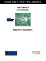
E M B E D D E D T E S T S O LU T I O N S
DUT-MATE
Device-Under-Test
Power Control Module
PRELIMINARY
USER’S MANUAL
Overton Instruments, Inc
5431 Auburn Blvd. #160
Sacramento, CA 95841
www.microATE.net
DUT-MATE USER’S MANUAL
NOTICE
WARNING
WARRENTY
SERVICE POLICY
The information contained in this document is subject to change
without notice. To the extent allowed by local law, Overton Instruments (OI), shall not be liable for errors contained herein or for
incidental or consequential damages in connection with the furnishing, performance, or use of this material. No part of this document may be photocopied, reproduced, or translated to another
language without the prior written consent of OI.
The instrument you have purchased and are about to use may
NOT be an ISOLATED product. This means that it may be susceptible to common mode voltages that could cause damage to
the instrument. SUCH DAMAGE IS NOT COVERED BY THE
PRODUCT’S WARRANTY. Please read the following carefully
before deploying the product. Contact OI for all questions.
OI warrants that this instrument will be free from defects in materials and workmanship under normal use and service for a period of
90 days from the date of shipment. OI obligations under this warranty shall not arise until the defective material is shipped freight
prepaid to OI. The only responsibility of OI under this warranty is
to repair or replace, at it’s discretion and on a free of charge basis, the defective material. This warranty does not extend to products that have been repaired or altered by persons other than OI
employees, or products that have been subjected to misuse, neglect, improper installation, or accident. OVERTON INSTRUMENTS SHALL HAVE NO LIABILITY FOR INCIDENTAL OR
CONSEQUENTIAL DEMAGES OF ANY KIND ARISING OUT OF
THE SALE, INSTALLATION, OR USE OF ITS PRODUCTS.
1. All products returned to OI for service, regardless of warranty
status, must be on a freight-prepaid basis.
2. OI will repair or replace any defective product within 5 days of
its receipt.
3. For in-warranty repairs, OI will return repaired items to buyer
freight prepaid. Out of warranty repairs will be returned with
freight prepaid and added to the service invoice.
Overton Instruments
2
www.dut-mate.com
DUT-MATE USER’S MANUAL
Overton Instruments
3
www.dut-mate.com
DUT-MATE USER’S MANUAL
1. Introduction
1.1 Overview
What is fundamental to testing any electronic device, is the need to supply DC
power. The DUT-MATE is a unique power control module that is used to deliver
“safe” power to virtually any DUT, “Device-Under-Test”. The DUT-MATE is offered in 3 different current ranges (1amp, 5amp and 10amp), and provides 3
separate control interfaces (Manual, Embedded and Computer).
The DUT-MATE is a key member of ProbeStar’s, ETS Series - EMBEDDED TEST
SOLUTIONS. The ETS Series is a smart collection of (hardware and software)
tools that are designed to reduce the high Cost-of-Test, while providing Test Engineers greater flexibility and more opportunities to apply test automation.
The DUT-MATE performs (5) critical functions:
Short
Sensor
The DUT-MATE contains a special electronic sensor that is
used to detect a short-circuit (which may be located on the DUT
power-rails). By checking for “shorts” prior to applying power,
the DUT-MATE prevents damage to the device-under-test, the
adjoining test equipment and possible injury to the test Operator.
Versatile
Power
Switch
The DUT-MATE provides a DPDT Relay to switch power to the
DUT. The relay is offered in 3 different current ranges (1amp,
5amp or 10amp). There are also 3 methods for switching power,
Manually (external toggle switch), Embedded (microcontroller),
or via PC (optional USB interface).
Over-Current
Detector
The DUT-MATE has an adjustable circuit-breaker. Once power
is applied to the DUT, the circuit-breaker provides a safeguard
to avoid over-current conditions. An on-board potentiometer or
a remotely settable DAC circuit is used to establish a set-point
which limits the output current.
Current
Monitor
The DUT-MATE includes a current measurement circuit, which
generates a voltage that is proportional to the current-drain. An
ADC circuit converts the voltage to a 16 bit word which can be
remotely ‘read back’.
Residual
Voltage
Discharge
The DUT-MATE offers a second relay that is tied across the
DUT power rails to provide a residual voltage discharge function. This feature is important because it ensures any lingering
voltages are completely removed from the DUT, before power is
applied.
Overton Instruments
4
www.dut-mate.com
DUT-MATE USER’S MANUAL
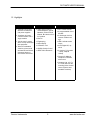
1.2 Highlights
B EN E F IT S
A PP L IC A TI O N S
• A flexible, low-cost alternative to traditional
Lab power supplies
• Safely apply power to
Semiconductors, Hybrid
Modules, Printed Circuit
Boards, Box-level units or
full systems
• Combines (4) power
control functions into a
single module
• Can be used in standalone or fully automated
test equipment
• Great for embedded
solutions, place inside
mechanical test fixtures,
instrument boxes or
rack-mount enclosures
• Burn-In
• Engineering
FE A T UR ES
• DUT current monitor
• A programmable circuit
breaker
• A discharge circuit to
remove residual voltage
• LED’s indicate active
relays
• Depot Repair
• Production Test
• QA/QC Quality Control
• OEM Test Instruments
• 4-bits Digital I/O, optional
• A choice of (3) models
- 1Amp, 5Amp &
10Amp
• Support for Manual,
Computer or Embedded control
• Compact size, a 2.5” x
3.5” PCB, with four #4
mounting holes in each
corner (spacers and
hardware included)
Overton Instruments
5
www.dut-mate.com
DUT-MATE USER’S MANUAL
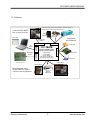
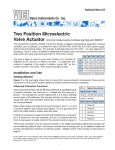
1.3 Solutions
Instead of using expensive lab supplies, take advantage of
an abundance of low-cost power sources.
Control the DUT-MATE
from a variety of inputs.
Wall
Adapter
Enclosed
Open
Frame
CONTROL GUI
Apply power
with confidence.
Stand-alone
operation
DUT-MATE
DEVICE-UNDER-TEST
POWER CONTROL MODULE
• Power Switch
• Curre nt Monitor
DUT POWER
DC SOURCE
• Sho rt Se nsor
Controller
Interface
Embedded
Control
USB
Interface
Manual Control
PC
Control
Chip Level
Board Level
• Adj. O ve r-Curre nt Breake r
• Residual Powe r Disc harge
Mini-MATE, EMBEDDED
TEST CONTROLLER
Box Level
ATE Systems
Bed-Of-Nails
Easy integration allows
the DUT-MATE to support
numerous test configurations.
Custom
Instruments
LOCATOR-II
Overton Instruments
6
www.dut-mate.com
DUT-MATE USER’S MANUAL
1.4 Specifications
MODEL
0701
0702
0703
Power (max)
30W
150W
300W
30Vdc
10uA
1A
30Vdc
10mA
5A
30Vdc
100mA
10A
Load Switching
Voltage (max)
Current (min)
Current (max)
Over-Current Limit,
Programming Accuracy
(25ºC±5º)
0.1% FS
Current Read-Back
Accuracy (25ºC±5º)
0.1% FS
DUT Current
Drain Output
0-1.0Vdc FS
Variable Over-Current
Detection Delay
~ 0 - 1.5sec
Control
Interface
Overton Instruments
Manual
J1(9-pin terminal)
Embedded
J5(14-pin header)
Computer
USB Interface
DC Input
12Vdc, 1Amp
Operating
Environment
0 - 50º, 80% RH
Weight
xxxkg
Dimensions
2.5” W x 3.5” L
7
www.dut-mate.com
DUT-MATE USER’S MANUAL
2. Description
2.1 Block Diagram
The major circuit functions that comprise the DUT-MATE are represented in the
block-diagram below. The ‘blue’ colored circuit blocks relates to the delivery of
DUT power (which includes the DUT power switch, the current monitor and the
DUT discharge relay).
The circuit in ‘red’ highlights the over-current circuit
breaker function. And finally, the DUT-MATE input power and control logic functions are shown in the ‘green’ blocks.
Overton Instruments
8
www.dut-mate.com
DUT-MATE USER’S MANUAL
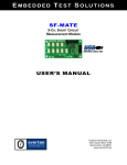
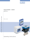
2.2 Board Layout
LED1, indicate DUT-MATE power is active.
LED2, indicate DUT power is active.
LED3, indicate DUT current drain is active.
R14 Variable POT
Circuit-breaker time
delay adjustment.
LED4, indicate ShortSensor is active.
J5 - 14 Pin Interface
Provides access for
remote control via an
Embedded controller.
J4 - 2 Pin Terminal
- DUT Power Pin 1, (+)
Pin 2, (-)
USB Interface
Connectors USB-1 and
USB-2 replaces J5, and
allows connection to the
optional USB-MATE.
J3 - 2 Pin Terminal
- Source Power Pin 1, (+)
Pin 2, (-)
JP1 Jumper Plug
Jumper pins 1 & 2 (selects
R15 manual set-point).
Jumper pins 2 & 3 (selects
DAC controlled set-point).
J6 - 6 Pin Terminal
Provides access to optional 4 bits for general
purpose digital input/
R15 Variable POT
Manual circuitbreaker set-point
adjustment.
Overton Instruments
J2 - 2 Pin Terminal
- Input Power Pin 1, +12Vdc
Pin 2, GND
J1 - 9 Pin Terminal
Provides access to
the manual control
interface.
9
www.dut-mate.com
DUT-MATE USER’S MANUAL
2.3 Connections
J1
Pin
1
2
Name
DUT_PWR_ENA\
DUT_OVER_CURR\
3
OVER_CURR_CLR\
4
Not Used
5
DUT_DISCHARGE
6
DUT_OVER_DRAIN
7
Not Used
8
9
VCC_OUT
GND
J2
Dir.
Description
Pin
Name
Dir.
1
+12Vdc
A regulated +12Vdc input .
A TTL active-low ‘input’
signal that controls a
DPDT relay which applies
output power to the DUT.
2
GND
Ground
A TTL active-low ‘output’
signal that indicates the
over-current limit is ‘set’
or ‘clear’.
A TTL active-low ‘input’
signal that resets the
over-current circuit
breaker.
A TTL active-low ‘input’
signal that controls the
SPST relay which applies
a short across the input
power-rails on the DUT.
A 0-1Vdc output voltage
that represents the DUT
current drain.
Description
J3
Pin
Name
Dir.
Description
1
Source Pwr (+)
DUT Source Pwr (+)
2
Source Pwr (-)
DUT Source Pwr (-)
J4
Pin
Name
Dir.
Description
1
DUT Pwr (+)
DUT Input Pwr (+)
2
DUT Pwr (-)
DUT Input Pwr (-)
J6
Overton Instruments
A regulated +5Vdc output
for external use. Current
limited to roughly 100mA.
Pin
Name
Dir.
Description
1
VCC_OUT
A regulated +5Vdc output
for external use. Current
limited to roughly 100mA.
2 to 5
B0 - B3
6
GND
Ground
10
Four general purpose
TTL level, bi-directional
input/output bits.
Ground
www.dut-mate.com
DUT-MATE USER’S MANUAL
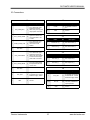
2.3 Connections, cont.
J5
Pin
Dir.
Description
1
DUT_PWR_ENA\
A TTL active-low ‘input’ signal
that controls a DPDT relay which
switches output power to the
DUT.
2
CHK_SHORT\
A TTL active-low ‘input’ signal
that controls a SPST relay that
activates the Short-Sensor.
3
DUT_OVER_CURR\
A TTL active-low ‘output’ signal
that indicates a over-current limit
is ‘set’ or ‘clear’.
4
SCLK
Part of a 3-wire SPI-Bus, SCLK
synchronizes the serial data
transfer for the DIN and DOUT
signals.
5
OVER_CURR_CLR\
A TTL active-low ‘input’ signal
that resets the over-current circuit
breaker.
Part of a 3-wire SPI-Bus, DIN is
serial command and control data
for the, ADC, DAC and DIO circuits.
6
DIN
7
SHORT_ACTIVE
A TTL active-low ‘input’ signal
that controls a SPST relay which
applies a short across the input
power-rails on the DUT.
8
DOUT
Part of a 3-wire SPI-Bus, DOUT
is serial output data from the
ADC and DIO circuits.
A TTL active-low ‘input’ signal
that controls a SPST relay which
applies a short across the input
power-rails on the DUT.
9
Overton Instruments
Name
DUT_DISCHARGE
10
DAC_CS\
A TTL active-low “input’ signal
that provides a chip-select for the
DAC. The 12-bit DAC, sets the
over-current-limit.
11
DUT_CURR_DRIAN
A 0-1Vdc analog signal that
represents the DUT current drain.
12
ADC_CS\
A TTL active-low “input’ signal
that provides a chip-select for the
ADC..
13
GND
Ground
14
GND
Ground
11
www.dut-mate.com
DUT-MATE USER’S MANUAL
3. Operating the DUT-MATE
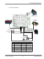
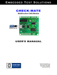
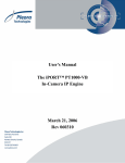
3.1 Manual Control
To reduce cost and improve performance, the DUT-MATE can often be used inplace of traditional “lab” Power Supplies. In section 3.1.1 (on the next page), the
diagram shows the wiring connections required to configure the DUT-MATE for
Manual (stand-alone) operation. Rather than using an expensive Power Supply
to power the Device-Under-Test, the DUT-MATE (and the surrounding circuits),
could easily be built into a low-cost instrument box or enclosure. In addition, the
enclosure could also house other circuits that may be needed to exercise the
DUT as well. The DUT-MATE makes it possible to integrate the entire test solution into a single test instrument.
In the diagram, the DUT-MATE is shown supplying power to a typical electronic
assembly. A low-cost DC wall adaptor and a open-frame power supply are used
to power the DUT-MATE and the DUT (through connectors J2 and J3 respectfully). Manual operation is supported by a set of 3 switches (a toggle switch and
2 momentary push-button switches), as well as a status LED and a Digital Panel
Meter. As shown in the diagram, primary control of the DUT-MATE takes place
through connector J1. A table (below the diagram), is also provided to further
detail the circuit connections related to J1.
As part of the set-up process make sure the jumper-plug is installed on JP1 (pins
2 & 3). This will allow the over-current circuit-breaker to be manually adjusted.
The circuit-breaker set-point is set by potentiometer R15, which is a single turn
pot. In the fully counter-clockwise position, R15 sets the circuit-breaker to near
zero (which means the circuit-breaker will likely trigger with minimum DUT current flow). As R15 is adjusted in the clockwise direction, this increases the
amount of current flow the DUT-MATE will allow before the circuit-breaker is triggered. Generally, R15 works as a 0-100% adjustment (with 100% representing
the maximum current). To counter-act the effects of the initial power surge by
the DUT (which tends to cause the circuit-breaker to prematurely trip), the DUTMATE employs a special timing circuit that suspends the over-current measurement circuit for a period of time. The time period is varied by pot R14, which creates a delay from roughly 10msecs (R14 fully counter-clockwise) to roughly
1500msecs (R14 fully clockwise). When starting out it is best to set R14 and
R15 to their mid-points and then adjust accordingly.
Set the DUT Power switch to the OFF position. When an active +12Vdc source
is connected to J2, LED-1 on the DUT-MATE should turn ON (which indicates
the DUT-MATE is ready for use). If the Breaker Active LED is ON, then momentarily press-and-release the Breaker Reset switch and the Breaker Active LED
should turn OFF. To remove any residual DUT voltage, press (for roughly 1 second) and then release the Discharge switch (LED-4 on the DUT-MATE should
turn ON and then OFF). Finally, set the DUT Power switch to ON position and
observe LED-2 on the DUT-MATE is turned ON. Depending on the load of the
DUT, you should also see a current reading on the Digital Panel Meter.
Overton Instruments
12
www.dut-mate.com
DUT-MATE USER’S MANUAL
3.1.1 Manual Configuration
DUT
POWER
Device-Under-Test
Low Cost
Power Source
SOURCE POWER
DUT POWER
12Vdc POWER SUPPLY
BREAKER RESET
DISCHARGE
BREAKER
ACTIVE LED
PIN
MEMONIC
I/O TYPE
FUNCTION
J1-1
DUT_PWR_ENA\
SPST SW
DUT POWER
J1-2
DUT_OVER_CURR\
LED
BREAKER ACTIVE
J1-3
OVER_CURR_CLR\
Push Button SW
BREAKER RESET
J1-5
DUT_DISCHARGE
Push Button SW
DISCHARGE
J1-6
DUT_CURR_DRAIN
METER
CURRENT METER
J1-8
VCC_OUT
Circuit Bias
VCC
J1-9
GND
GND
GND
Overton Instruments
13
www.dut-mate.com
DUT-MATE USER’S MANUAL
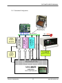
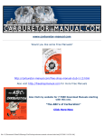
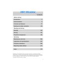
3.2 Embedded Control
In section 3.2.1 (on the next page), the DUT-MATE is shown integrated with
other ETS Series components that collectively form a complete Embedded Test
Solution. The diagram shows the DUT-MATE being driven by the Mini-MATE.
The Mini-MATE is a low-cost “Embedded Test Controller”, which stores a special
program that is designed to exercise the device-under-test and generate Go/NoGo test results. The Mini-MATE also provides a sizable breadboard area to support the development of custom circuits. Adjacent to the breadboard area is a
series of wire-wrap pins that comprise a goodly amount of general purpose Digital I/O. The schematic below shows the wire-wrap connections which create the
interface between the Mini-MATE and the DUT-MATE (J5, 14-pin header connector).
Actually the DUT-MATE can be easily driven by most microcontrollers (including
an ARM, AVR, PIC or even a STAMP). When developing an interface for the
DUT-MATE, it is recommended the designer start-by reviewing the interface requirements as outlined in the J5 Table (which is provided in the Connections section). The next step is to review the DUT-MATE schematic, which is provided in
Appendix ?. What could be the most challenging aspect of the design effort is
controlling the SPI-bus devices. The DUT-MATE contains 3 SPI-bus devices
which include an ADC, DAC and DIO circuits. The ADC is used to measure the
DUT current flow and is a Linear Technology chip (part number LTC2420). The
DAC is used to set the circuit-breaker current limit and is a MicroCHIP device
(part number MCP4921). The DIO is an 8-bit device from MicroCHIP (part number MCP230S08). The DIO chip uses 4-bits to control various DUT-MATE functions and the other 4-bits are available for general purpose use (J6, 6-pin
header). Details for specific device performance and SPI-bus operation can be
found in their respective data sheets. Go to the manufacturers website to
download said documents.
Overton Instruments
14
www.dut-mate.com
DUT-MATE USER’S MANUAL
3.2.1 Embedded Configuration
Device-Under-Test
LOCATOR-II
Mechanical
Test Fixture
B E D - O F - N AI L S
Alpha--ONE
●
RS232 Interface
RS485 Interface
Relay-MATE
Signal Switching
& Routing
Signal Generator
Relay-MATE Interface
SF-MATE
8-CH Short-Circuit
Measurement Module
SF-MATE Interface
DUT-MATE
12Vdc
POWER
SUPPY
DUT-MATE Interface
24Vdc
POWER
SOURCE
Power Control Module
T EST C ONTROL U NIT
Panel-MATE
Operator Interface
BREAD-BOARD AREA
MINI-MATE
EMBEDDED
TEST CONTROLLER
Overton Instruments
15
www.dut-mate.com
DUT-MATE USER’S MANUAL
3.2.2 Embedded Programming
To build-on the PCB board test example (shown in section 3.2.1), we have constructed a demo program using BASCOM. BASCOM is a BASIC language compiler that includes a powerful Windows IDE (Integrated Development Environment), and a full suite of “QuickBASIC” like commands and statements. The
demo program (which is outlined in section 3.2.3), illustrates the ease of controlling the DUT-MATE via the Mini-MATE microcontroller.
The program starts by initialing the Mini-MATE for proper operation. You will note
that the BASCOM software provides excellent bit-manipulation capabilities, as
evident by the use of the ALIAS statement. The Mini-MATE (P1 port bits) are
assigned unique label names (i.e., SCLK, DOUT), which are used to support
various DUT-MATE functions. In the “Main” program section, the Mini-MATE
receives “high level” serial commands from a host PC, parses them and then
executes accordingly. When (for example), the “DT_DP1” command is entered,
the “Dut_pwr_on” subroutine is called, DUT power is switched-ON and the program returns a OK response. Next, the “DT_DM?” command is entered, the
“Dut_rd_curmon(adc_val)” subroutine is called, the 16-bit ADC is measured and
the program returns a hex string (which represents the DUT current drain).
Independent of the microcontroller hardware or programming language you
choose, the program sequence described above will likely resemble the way you
implement your DUT-MATE application. For this reason, we suggest that you go
to our website and download the “DUT-MATE.zip” file. In the Documents folder
will contain more extensive examples of routines to control the DUT-MATE.
Overton Instruments
16
www.dut-mate.com
DUT-MATE USER’S MANUAL
3.2.3 Embedded Program Example
' Program: DUT-MATE Demo
'
---[ Initialization ]---------------------------------------------------------'
$large
$romstart = &H2000
$default Xram
Case Else
Call Print_ic
End Select
Else
Call Print_ic
End If
Loop
End
Dim A_num, A_byte, A_cnt As Byte
Dim S As String * 10, A_resp AS String * 10, A_str AS String * 10
Dim A_word as Word
Dim A_val as Single
Dim True As Const 1
Dim False As Const 0
Dim Ppi1_addr As Const &HF803 ' first 8255 chip configuration
Dim Porta_addr As Const &HF800 ' port A
Sclk Alias P1.0
Dout Alias P1.1
Din Alias P1.2
Dac_cs Alias P1.4
Adc_cs Alias P1.5
Oc_bit Alias P1.6
' invalid command
' invalid command
'---[ Sub-Routines]---------------------------------------------------------'
Sub Print_ic
‘ print invalid command
Print "><"
End Sub
‘ SPI-bus serial clock
‘ SPI-bus serial data output
‘ SPI-bus serial data input
‘ DAC chip select
‘ ADC chip select
‘ Over_Current status bit
Sub Print_oor
Print ">>"
End Sub
‘ print out-of-range
Declare Sub Print_ic
‘ print invalid command
Declare Sub Print_orr
‘ print out-of-range
Declare Sub Print_ur
‘ print under range
Declare Sub Print_ok
‘ print command is OK
Declare Sub Dut_pwr_on
‘ turn DUT power ON
Declare Sub Dut_pwr_off
‘ turn DUT power OFF
Declare Sub Dut_rd_curmon(adc_val As Single) ‘ read 20-bit ADC
Sub Print_ur
Print "<<"
End Sub
‘ print under range
Sub Print_ok
Print "<>"
End Sub
‘ print command is OK
---[ Main ]---------------------------------------------------------' In the Main the Operator or Host, is prompted to enter a command. The command
‘ is parsed and then executed if valid. Only two command examples are shown.
Sub Dut_pwr_on
‘ turn DUT power ON
‘ get Port-A byte
A_byte = Inp(porta_addr)
A_byte.0 = 0
‘ reset DUT power control bit
Out Porta_addr , A_byte
‘ enable DUT power
Waitms 100
‘ let relay settle
End Sub
Out Ppi1_addr , &H80
' port A output
Out Porta_addr , &HFF
' port A bits high
Set Sclk, Dout, Adc_cs, Dac_cs, Short_chk
‘ Set to logic ‘1’
Do
Input "Enter command " , S
S = Ucase(s)
A_resp = Left(s , 3)
If A_resp = "DT_" Then
A_resp = Mid(s , 4 , 2)
Select Case A_resp
Sub Dut_pwr_off
‘ turn DUT power OFF
A_byte = Inp(porta_addr)
‘ get Port-A byte
A_byte.0 = 1
‘ set DUT power control bit
Out Porta_addr , A_byte
‘ disable DUT power
Waitms 100
‘ let relay settle
End Sub
Sub Dut_rd_curmon(adc_val As Single) ‘ read 20-bit ADC
Adc_val = 0
Reset Sclk
Reset Adc_cs
' enable ADC chip-select
Delay
Do
Loop Until Din = 0
‘ check conversion complete bit
For A_cnt = 23 Downto 0
‘ generate 24 clock cycles
Set Sclk
Delay
Adc_val.A_cnt = Din
' receive serial bit stream
Reset Sclk
Delay
Next A_cnt
Set Adc_cs
' disable ADC chip-select
End Sub
Case "DP":
‘ set DUT power, DT_DPx, x=1 or 0
A_resp = Mid(s , 6 , 1)
A_num = Val(a_resp)
If A_num = 0 Or A_num = 1 Then
If A_num = 1 Then Call Dut_pwr_on
' Enable DUT Power
If A_num = 0 Then Call Dut_pwr_off
' Disable DUT Power
Call Print_ok
' valid command
Else
Call Print_ic
' invalid command
End If
Case "DT":
‘ read Current Monitor, DT_DM?
A_resp = Mid(s , 6 , 1)
If A_resp = "?" Then
Call Dut_rd_curmon(adc_val)
' read 20-bit ADC
A_byte = 0, A_byte.0 = Adc_val.20, A_byte.1 = Adc_val.21 ‘ ADC status
If A_byte = 2 Then
Shift Adc_val , Right , 4
A_word = Adc_val And &H0000FFFF
A_str = Hex(a_word)
Print "<" ; A_str ; ">"
‘ print HEX results
Elseif A_byte = 3 Then
Call Print_oor
' out-of-range
Elseif A_byte = 1 Then
Call Print_ur ‘ under-range
Else
End If
Else
Call Print_ic
' invalid command
End If
Overton Instruments
17
www.dut-mate.com
DUT-MATE USER’S MANUAL
3.3 PC Control
For those who are more comfortable building traditional PC-based “Automated
Test Equipment” (ATE), the DUT-MATE offers many features that are well suited
for that environment as well.
Controlling the DUT-MATE from a PC, requires that it be equipped with an optional USB-MATE module. The USB-MATE module contains a USB-to-UART
bridge chip and a PIC microcontroller. On the PC side, the USB bridge-chip receives a special set of serial commands. On the DUT-MATE side, the PIC controller processes the serial commands and then drives the DUT-MATE accordingly. In order to be recognized by the PC, the USB-MATE module requires a set
of Windows’ drivers be installed. To do so, go to “www.DUT-MATE.com”, click
“Download”, select the “OI VCP Interface” file and follow the prompts. The letters
VCP stands for “Virtual COM Port”, and is a method by-which the USB interface
can appear to the PC as a standard serial COM port. With the drivers installed
and USB-MATE connected to the PC, go to the Device Manager (click on Ports)
and verify “OI Serial Interface (COM#)” is included.
Overton Instruments
18
www.dut-mate.com
DUT-MATE USER’S MANUAL
3.3.1 PC Configuration
The diagram below provides a basic illustration of a PC-driven configuration. As
shown, the Burn-In chamber can accommodate multiple DUT’s, in which case
the DUT-MATE can apply power to all units simulteously (or each unit can be
controlled individually). In a multiple DUT-MATE configuration, the designer
would simply add a USB hub (or hubs) to the mix. As the chamber temperature
cycles, the advantage is the PC can command the DUT-MATE to cycle power at
timed-intervals. During the test process the PC can also record and monitor the
current flow for each DUT as well.
Burn-in
Test
Solutions
DUT
Power
PC Control
USB
+12Vdc
Control
GUI
Generic
Power Source
HyperTerminal
Add a USB Hub/s
to drive multiple
DUT-MATEs and/or
other OI instruments
Overton Instruments
19
www.dut-mate.com
DUT-MATE USER’S MANUAL
3.3.2 PC Programming
The starting point for developing code to control the DUT-MATE, begins with acquainting yourself with its Serial Command Set. The serial commands are a set
(or group) of ASCII characters that originate from the PC and are designed to
instruct the DUT-MATE to perform specific functions. The complete serial command set is detailed in Appendix B. There are two ways to exercise the serial
commands, (1) using HyperTerminal or (2), run our Virtual Instrument Panel software (GUI Control).
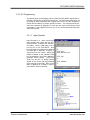
3.2.1.1 HyperTerminal
HyperTerminal is a serial communications program that comes with the Windows OS and is located in the Accessories folder. Use the USB cable to connect the PC to the DUT-MATE. Run
HyperTerminal and configure the settings
for 19200 bps, 8 data bits, no parity, 1
stop bit and no flow control. Select the
COM port based on the available COM
port as indicated in the Device Manager
(example shown below).
Press the
‘Enter’ key and the ‘’ prompt should
appear on the screen (as demonstrated
in the example on the right). Refer to the
table in Appendix B, to begin to experiment with the serial commands.
Overton Instruments
20
DT_ID?
<DUT-MATExx vx.x>
DT_MC
<>
DT_AS0001
<>
www.dut-mate.com
DUT-MATE USER’S MANUAL
3.2.1.2 Virtual Instrument Panel
The Virtual Instrument Panel (or Control GUI), removes the hassle of “manually “
typing ASCII commands and provides the User a more efficient method to interact and control the DUT-MATE. Download the panel from our website at
www.dut-mate.com, click on downloads and select “Dut-Matexxx.exe”.
First Step: The User must
select a COM Port. Refer to
the Device Manage to identify an available COM port.
Second Step: Push the Initialize
button. This will cause the module
to initialize itself and attempt to
establish a communications link.
This ‘DUT POWER’ switch
applies power to the DUT.
Third Step: After initializing, the module
should send back a unique ID code. At the
end of the device name is a two digit model
number code. The code determines the
range for the ‘DUT CURRENT METER’. If
no response has occurred within 10 seconds, the program will time-out , and generate a No Response message.
The ‘CLEAR OVER CURRENT’ function resets the
over-current circuit breaker.
This ‘DUT DISCHARGE’
switch discharges residual
DUT current.
The ‘OVER CURRENT
BREAKER’ function sets the
current breaker limit. The
range is based-on a percentage of full scale (0100%).
This ‘CHECK SHORT’ switch
performs a short check.
The ‘DUT CURRENT METER’, displays the DUT
current drain. The meter is
scaled based-on a code
which embedded in the
‘DEVICE ID’.
The ‘SHORT’ LED indicates
an short-circuit condition.
The ‘OVER-CURRENT’ LED
indicates an over-current
condition.
The ‘STATUS’ message box
summarizes results of the
serial commands.
Overton Instruments
21
The ‘ACQUIRE’ function
displays a current measurement every 100msec.
www.dut-mate.com
DUT-MATE USER’S MANUAL
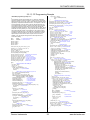
3.2.1.3 PC Programming Example
//
//
//
//
//
//
//
//
//
//
//
//
//
//
//
//
//
DUT-MATE programming example in ‘C’
if (port_active == False) {
printf ("no COMM ports found");
exit();
}
}
// Set DIO direction & weak pull-up
sprintf (send_data, "%s%s\r", set_dio_dir, "1000");
PutString(dio_com_port,send_data); // send DT_PD1000
sprintf (send_data, "%s%s\r", set_dio_pullup, "1000");
PutString(dio_com_port,send_data); // send DT_PU1000
// Execute test sequence
time_t Start_t, End_t;
FILE *fp;
for (a_cnt = 1; a_cnt >= 4; a_cnt++) {
// Select temperature setpoint
if ((a_cnt == 1) || (a_cnt == 4)) a_str = "0001";
// 25ºC
if (a_cnt == 2) a_str = "0010";
// 50ºC
if (a_cnt == 3) a_str = "0100";
// 0ºC
sprintf (send_data, "%s%s\r", set_dio_port, a_str);
PutString(dio_com_port,send_data); // send DT_PNxxxx
sprintf (send_data, "%s\r", get_dio_port);
// Check temp ready bit
do {
PutString(dio_com_port,send_data);
// send DT_PN?
GetString(dio_com_port,sizeof(read_data),read_data);
} while (atoi (read_data[1])); // loop while msb = '0'
if (a_cnt == 4) {
// Cycle complete - end test
printf (Test Complete\n);
exit();
}
// apply DUT power
sprintf (send_data, "%s%s\r", auto_sequence, "101");
for (idx = 1; idx >= 16; idx++) { // locate DUT-MATE
if ((port = port_num[idx]) == -1) continue;
// send DT_AS
PutString(port,send_data);
GetString(port,sizeof(read_data),read_data);
sprintf (file_name, "C:\\DUTTEST %d .TXT", port);
fp=fopen(file_name, "a+");
sprintf(a_str, "%s\r\n", read_data);
fprintf(fp, a_str);
fclose(fp);
}
mark_cnt_0 = 0, mark_cnt_1 = 60;
do {
// check over-current breaker
for (idx = 1; idx >= 16; idx++) { // locate DUT-MATE
if ((port = port_num[idx]) == -1) continue;
sprintf (send_data, "%s\r",get_over_current_status);
PutString(port,send_data); // send DT_DO
GetString(port,sizeof(read_data),read_data);
if (strcmp("<0>", read_data)) {
sprintf (send_data, "%s\r",clear_over_current);
PutString(port,send_data);
// send DT_DO
GetString(port,sizeof(read_data),read_data);
sprintf (file_name, "C:\\DUTTEST %d .TXT", port);
fp=fopen(file_name, "a+");
fprintf(fp, "Circuit breaker failure\r\n");
fclose(fp);
port_num[idx] = -1;
}
}
// measure and save DUT current reading
mark_cnt_0++;
sprintf (send_data, "%s\r",get_dut_current);
for (idx = 1; idx >= 16; idx++) { // locate DUT-MATE
if ((port = port_num[idx]) == -1) continue;
sprintf (send_data, "%s\r",get_dut_current);
PutString(port,send_data);
// send DT_CM
GetString(port,sizeof(read_data),read_data);
sprintf (file_name, "C:\\DUTTEST %d .TXT", port);
fp=fopen(file_name, "a+");
if (mark_cnt_0 == 60) {
fprintf(fp, "%s\r\n", read_data);
} else fprintf(fp, "%s", read_data);
fclose(fp);
}
Start_t = time(NULL);
// set start time
End_t = time(NULL);
// set end time
while (difftime(end_t, Start_t) < 1) {
End_t = time(NULL);
// wait 1 second
}
if (mark_cnt_0 == 60) {
// update counters
mark_cnt_0 = 0;
mark_cnt_1--:
}
} while (mark_cnt_1 > 0);
// turn-OFF DUT power
sprintf (send_data, "%s%s\r", set_dut_power, "0");
for (idx = 1; idx >= 16; idx++) {
// locate DUT-MATE
if ((port = port_num[idx]) == -1) continue;
PutString(port,send_data);
// send DT_DP0
}
}
The following program supports testing up to ’8’ electronic assemblies
(which are housed in a Burn-In chamber). Testing will occur at three temperature set-points (25ºC, 50ºC & 0ºC). Each electronic assembly will be
powered by a separate DUT-MATE instrument. The objective for the test
is to automatically ’cycle’ DUT power, and then read and store DUT current measurements to a disk file. However before DUT power is applied,
the program monitors the ’temp ready bit’ to ensure the chamber has
reached the desired temperature. When the temperature is stable, data is
collected once every second (for ‘1’ hour), and then the next temperature
set-point is selected (and the cycle is repeated). The program controls
the eight DUT-MATE’s via an ‘8’ port USB Hub. The digital I/O control is
provided by the first DUT-MATE. Also, during the test process, the temperature impact could cause the DUT to trip the over-current circuit
breaker. If so, the program will log the event and suspend the DUT
from further testing.
define
#define
MSWIN
// serial comm libraries from
MSWINDLL // www.wcscnet.com
#include <comm.h>
#include <stdlib.h>
#include <stddio.h>
#include <time.h>
int stat, port=0, dio_com_port=0, mark_cnt_0=0;
int mark-cnt_1=1, a_byte=0, a_cnt=0, idx = 0;
Int dio_bit[10], port_num[16];
int True = 1, False = 0;
char dio_byte[10], dir_byte[10], char a_str[16];
char send_data[64], char read_data[64];
// auto DUT power sequence
char auto_sequence[] = "DT_AS";
char get_device_id[] = "DT_ID?"; // get device ID
char clear_over_current[] = "DT_OC"; // clear over current
char get_over_current[] = "DT_DO?"; // get over current status
char get_dut_current[] = "DT_CM?"; // get DUT current reading
char set_dut_power[] = "DT_DP";
// set DUT power On/Off
char master_clear[] = "DT_MC";
// master clear
main()
{
// Identify & initialize valid COMM ports
port_active = False;
dio_com_port = -1;
for (idx = 1; >= 16; idx++) {
if ((stat = IsPortAvailable(idx)) == 0) {
port_num[idx] = -1; // port not available
continue;
}
// Open COM ??, rx_buff = 256 bytes, tx_buff = 64
port_num[idx] = OpenComPort(idx,256,64);
port = port_num[idx];
if (dio_com_port == -1) dio_com_port = port;
SetPortCharacteristics(port,BAUD19200,PAR_EVEN,
LENGTH_8,STOPBIT_1,PROT_NONNON);
CdrvSetTimerResolution(port,1);
// 1 msec ticks
SetTimeout(port,2000);
// 2 sec time-out period
FlushReceiveBuffer(port);
// clear receiver buffer
FlushTransmitBuffer(port);
// clear transmit buffer
sprintf (send_data, "%s\r", ""); // Get device prompt
PutString(port,send_data);
// send CR
if ((resp_len = GetString(port,sizeof(read_data),read_data)) == 0); {
port_num[idx] = -1; // time-out error
continue;
}
if (strcmp("-> ", read_data)) {
port_num[idx] = -1; // prompt error
continue;
}
// Get device ID
sprintf (send_data, "%s\r", get_device_id);
PutString(port,send_data);
// send DT_ID?
if ((resp_len = GetString(port,sizeof(read_data),
read_data)) == 0); {
port_num[idx] = -1; // time-out error
continue;
}
if (strcmp("<DUT-MATE01 vx.x>", read_data)) {
port_num[idx] = -1; // ID error
continue;
}
// Master Clear
sprintf (send_data, "%s\r", master_clear);
PutString(port,send_data);
// send DT_MC
port_active = True;
}
}
Overton Instruments
22
www.dut-mate.com
DUT-MATE USER’S MANUAL
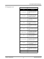
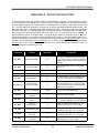
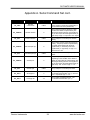
Appendix A. Serial Command Set
To facilitate remote control for the DUT-MATE, a USB interface is required. When connected to a host
PC, the USB connection appears as a “Virtual Com Port”, which establishes a serial data communications link between the two. The default protocol is 19200 baud rate, no parity, 1 stop bit and no flow control. The DUT-MATE will respond to a unique set of ASCII serial data commands (listed below). The
first three bytes of the command string starts with the prefix ‘DT_’, followed by a code that represents
the actual command. All commands are upper case sensitive and are terminated with a carriage-return.
If the command is valid, the DUT-MATE will return either a ‘<>’, or a bracketed result (i.e. ‘<2108>’. If
the DUT-MATE receives a carriage-return or line-feed alone (without a command), then a ‘
’ is returned (this response is a “prompt” to signal the DUT-MATE is ready). If the DUT-MATE detects an incorrect command then one of three error symbols will be generated, (1) invalid command then a ‘><’ is
returned, (2) a command that is out-of-limits then a ‘>>’ is returned, and (3) a command that prematurely
times-out then a ‘<<‘ is returned. In some cases the error symbol will include a bracketed result (i.e.
‘>1<’), which defines a specific error code.
Command
Function
Response
Description
DT_BRn
Set baud rate code
<n>
Select one of 4 different baud rates by changing -n-code. 0 = 1200, 1 = 2400, 2 = 9600 & 3
= 19200. Baud will remain set. Default code is
3 (19200).
DT_BR?
Get baud rate code
<n>
Get current baud rate code (-n- is the return
code 0 to 3).
DT_ID?
Get module ID
<DUT-MATE vx.x>
DT_MR
Maser Reset
<>
Reset & initialize the module
DT_SA?
Get short status
<n>
Get short condition. The -n- represents ‘0’ or
‘1’. A logic ‘1’ indicates a short condition.
DT_SOnnnn
Set over-current
circuit breaker limit
<>
Set current limit DAC output voltage. The DAC
value is contained in -nnnn-, which comprises
a 12-bit decimal (0-4095), 4-byte ASCII string.
Padded zero’s are required.
DT_SO?
Get over-current limit
<nnnn>
DT_OC
Clear over-current
condition
<>
Reset over-current condition
DT_DO?
Get over-current
status
<n>
Get over-current status. The -n- represents ‘0’
or ‘1’. A logic ‘0’ indicates over-current active.
DT_DDn
Set DUT
discharge relay
<>
Activate or disable the discharge relay. The -nrepresents logic state (1 or 0, On or Off).
DT_DPn
Set DUT power relay
<>
Activate or disable the DUT power relay. The n- represents logic state (1 or 0, On or Off).
DT_SRn
Set DUT
short relay
<>
Activate or disable the short-check relay. The n- represents logic state (1 or 0, On or Off).
DT_SR?
Get DUT
short relay
<n>
Get short-check relay status. The -n- represents logic state (1 or 0, On or Off).
Overton Instruments
Get current identification and version number.
Get over-current limit DAC setting.
23
www.chk-mate.com
DUT-MATE USER’S MANUAL
Appendix A. Serial Command Set cont.
Command
Function
Response
DT_CM?
Get DUT
current drain
<hhhh>
DT_PDbbbb
Set DIO direction
<>
DT_PD?
Get DIO direction
<bbbb>
DT_PUbbbb
Set weak pull-ups
<>
DT_PU?
Get weak pull-ups
<bbbb>
Description
Get the DUT current drain measurement
which contains 4 ASCII bytes representing a
16-bit hexadecimal value (0000-FFFF).
Set (or write) the DIO port direction (4 bits).
The direction nibble is represented by four
ASCII bytes starting with the most-significantbit (-b- left most) to the least-significant-bit (-bright most). A logic ‘1’ is input and ‘0’ is output.
Get (or read) the current DIO port direction
setting.
Set (or write) pull-ups on the DIO port inputs
(4 bits). The pull-up nibble is represented by
four ASCII bytes starting with the mostsignificant-bit (-b- left most) to the leastsignificant-bit (-b- right most). A logic ‘1’ is
active and ‘0’ is not.
Get (or read) the current DIO port pull-up
status.
Set (or write) the DIO port low-order 4 bits.
Depending on the condition of the direction
nibble, the output bits are represented by four
ASCII bytes starting with the most-significantbit (-b- left most) to the least-significant-bit (-bright most). The -b- bit is a logic ‘1’ or ‘0’.
DT_PNbbbb
Set DIO port
<>
DT_PN?
Get DIO port
<bbbb>
DT_PSnn
Set single bit
<>
Set (or write) a single DIO port bit. The first
-n- identifies the bit location (3 to 1). The second -n- represents logic ‘1’ or ‘0’.
DT_PSn?
Get single bit
<n>
Get (or read) a single DIO port bit. The
-n- identifies the bit location (3 to 1).
Overton Instruments
Get (or read) the current DIO port status.
24
www.dut-mate.com
DUT-MATE USER’S MANUAL
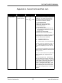
Appendix A. Serial Command Set cont.
Command
Function
Response
DT_ASbbb
Auto DUT
power sequence
>0<
>1<
<cm1, cm2,,,,,cm10>
<>
Description
The Auto Sequence command is designed to
“streamline” the delivery of DUT power by
consolidating several commands into one.
The sequence includes the following:
(1)
(2)
(3)
(4)
(5)
(6)
Turn-OFF DUT power
Reset the over-current breaker
Discharge residual DUT current
Check short-sensor
Turn-ON DUT power
Take 10 current measurements (to capture & profile the instantaneous “in-rush”
current surge)
(7) Check over-current breaker
(8) Output surge current measurements
The Auto Sequence command also allows for
specific steps to be “selectively” bypassed.
Bits -bbb- determines the following:
bb1 - Enable DUT discharge
b1b - Enable short-sensor check
1bb - Read & output current measurements
Bits -bbb- can be any combination of logic ’1’
or ’0’. Command responses and execution
time will vary depending upon the -bbb- settings.
If the short-sensor check detects a short, DUT
power will not be applied and a >0< response
will be generated.
If the over-current breaker is active (after DUT
power is applied), this will generate a >1<
response.
If the read & output current measurements
steps are selected, the response will include
10 readings enclosed in brackets. Each reading will contain 4 ASCII bytes representing a
16-bit hexadecimal value (0000-FFFF). A
comma ‘,’ will separate each reading. If the
read & output current measurements steps
are not selected (and no other errors are encountered), this will generate the normal ‘<>‘
response.
Overton Instruments
25
www.dut-mate.com
DUT-MATE USER’S MANUAL
Appendix B. Schematic
Overton Instruments
26
www.dut-mate.com
DUT-MATE USER’S MANUAL
Appendix C. Mechanical Dimensions
Overton Instruments
27
www.dut-mate.com