1
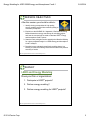
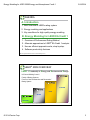
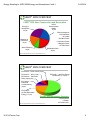
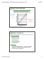
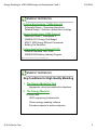
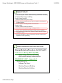
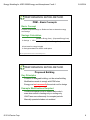
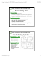
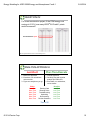
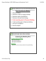
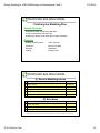
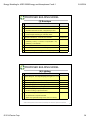
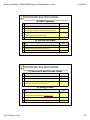
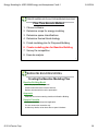
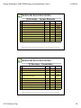
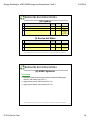
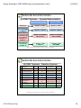
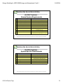
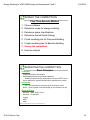
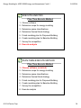
Energy Modeling for LEED 2009 Energy and Atmospheres Credit 1 9/16/2014 Bob Feduik, P.E., LEED BD&C, BEMP Regional Sales Manager Software Systems © 2013 Carrier Corporation EDUCATION AND CREDENTIAL CREDITS In order to receive a certificate for this course you must both: 1. Sign the workshop attendance sheet which demonstrates that you have attended the workshop This will be passed around the room at the start of the workshop. Print legibly so that information can be easily verified. 2. Complete the Survey At the end of the workshop, you must also complete the workshop evaluation. Turn in the Evaluation to the moderator. Certificates will be sent to you. Under the November 2012 rule, this course may qualify for GBCI LEED CMP credit under the Educational Category LEED® is a registered trademark of the U.S. Green Building Council. © 2014 Carrier Corp. 2 1 Energy Modeling for LEED 2009 Energy and Atmospheres Credit 1 9/16/2014 SESSION OBJECTIVES After this session you should be able to: 1. Identify the key prerequisites for high quality energy modeling and the risks created by failing to meet each prerequisite 2. Explain how the ASHRAE 90.1 Appendix G Performance Rating Method determines energy cost savings for a building project, and how the cost savings are used to calculate LEED® Energy and Atmosphere Credit 1 points 3. State the basic principles used to assemble the Baseline Building for a given proposed Design in a LEED® Energy and Atmosphere Credit 1 analysis 4. Describe how to evaluate thermal block modeling issues in a building to minimize modeling cost and at the same time preserve accuracy of results LEED is a registered trademark of the U.S. Green Building Council. 3 SURVEY LEED and Energy Modeling Does your firm or organization: 1. Participate in LEED® projects? 2. Perform energy modeling? 3. Perform energy modeling for LEED® projects? LEED is a registered trademark of the U.S. Green Building Council. © 2014 Carrier Corp. 4 2 Energy Modeling for LEED 2009 Energy and Atmospheres Credit 1 9/16/2014 AGENDA A. Introduction 1. Brief overview of LEED® rating system 2. Energy modeling and applications 3. Key conditions for high quality energy modeling B. Energy Modeling for LEED EA Credit 1 1. Overview of Performance Rating Method 2. Alternate approaches to LEED® EA Credit 1 analysis 3. How an efficient approach works, step-by-step. 4. Software productivity features 5 LEED is a registered trademark of the U.S. Green Building Council. LEED® 2009 OVERVIEW LEED = Leadership in Energy and Environmental Design US Green Building Council Family of Rating Systems Focus on “New Construction and Renovation” Rating System PLATINUM GOLD SILVER CERTIFIED LEED is a registered trademark of the U.S. Green Building Council. © 2014 Carrier Corp. 6 3 Energy Modeling for LEED 2009 Energy and Atmospheres Credit 1 9/16/2014 LEED® 2009 OVERVIEW LEED® 2009 New Construction and Renovation Indoor Environmental Quality 15 pts Energy & Atmosphere 35 pts 5 Base Categories 8 Prerequisites 32 Credits 100 Base Points Materials & Resources 14 pts 6 Innovation Points 4 Regional Points 110 Total Points Water Efficiency 10 pts Sustainable Sites 26 pts 7 LEED is a registered trademark of the U.S. Green Building Council. LEED® 2009 OVERVIEW EA Credit 6 – Green Power (2 pts) EA Credit 5 – M+V (3 pts) EA Credit 1 - Optimize Energy Performance (1-19 pts) EA Credit 4 – Enhanced Refrig. Mgt (2 pts) EA Credit 3 – Enhanced Commissioning (2 pts) EA Credit 2 – On-Site Renewable Energy (1-7 pts) Energy and Atmosphere Category 3 Prerequisites 6 Credits 35 Credit Points LEED is a registered trademark of the U.S. Green Building Council. © 2014 Carrier Corp. 8 4 Energy Modeling for LEED 2009 Energy and Atmospheres Credit 1 9/16/2014 LEED® 2009 OVERVIEW EA Credit 1 – Energy Modeling Approach Earn 1 to 19 pts based on energy cost savings Different scales for New Construction and Renovation 19 Existing Bldg Renovation: 18 8% = 1pt to 44% = 19 pts 15 17 LEED® EA Credit 1 Points 16 14 13 12 11 10 9 New Construction: 8 12% = 1pt to 48% = 19 pts 7 6 5 4 3 2 1 0 8 12 16 20 24 28 32 36 40 44 48 % Energy Cost Savings LEED is a registered trademark of the U.S. Green Building Council. 9 ENERGY MODELING Alternate Terms Energy Modeling Energy Simulation Energy Analysis Energy Estimating Opcost Analysis Definition Classical Energy Modeling - Creating a computer model of a building and its systems to predict annual energy consumption. 10 © 2014 Carrier Corp. 5 Energy Modeling for LEED 2009 Energy and Atmospheres Credit 1 9/16/2014 ENERGY MODELING Original Applications (1960s-Present) Schematic Design – Screening alternatives Detailed Design – Selection, optimization of design Recent Applications (2000-Present) LEED® EA Credit 1, Prerequisite 2 ASHRAE 90.1 Energy Cost Budget EPACT 2005 Energy Efficient Commercial Building Tax Deduction Future Applications (Beyond 2010) ASHRAE Standard 189.1-2009 ASHRAE EQ Building Labeling Program LEED is a registered trademark of the U.S. Green Building Council. 11 ENERGY MODELING Key Conditions for High Quality Modeling 1. The Energy Modeling Tool Appropriate, robust tool matched to objectives 2. The Energy Modeler Proficient with: HVAC engineering fundamentals Chosen energy modeling software Procedure required to achieve objective 12 © 2014 Carrier Corp. 6 Energy Modeling for LEED 2009 Energy and Atmospheres Credit 1 9/16/2014 QUESTION #1 Select (circle) the 3 items which are key conditions necessary for high quality energy modeling: Energy modeling software: a. Must use an 8760 hour-by-hour analysis. b. Must be sufficiently detailed and have features capable of supporting your modeling objectives. c. Must be capable of modeling at least 10 thermal zones. Energy modeler: d. Must be a LEED accredited professional. e. Must understand the required energy modeling procedure. f. Must be an accredited Building Energy Modeling Professional (BEMP) g. Must understand the chosen energy modeling software operation, features, calculations, reports. h. Must hold a BS degree or higher in engineering and have at least 5 years experience in HVAC engineering. 13 PERFORMANCE RATING METHOD Energy Modeling Procedure for EA Credit 1 Performance Rating Method (PRM) Rates energy efficiency of buildings which exceed energy code provisions ASHRAE 90.1-2007 – Appendix G Requirements for: Software Tool Used Modeling Proposed Building Modeling Baseline Building 14 © 2014 Carrier Corp. 7 Energy Modeling for LEED 2009 Energy and Atmospheres Credit 1 9/16/2014 PERFORMANCE RATING METHOD PRM – Basic Concepts Basic Concept Compare Proposed Design vs. Reference Case to determine energy cost savings Savings Calculation % Savings = 100 x (Baseline Energy Cost) – (Proposed Energy Cost) (Baseline Energy Cost) All end uses for energy included % Savings translates into LEED® credit points LEED is a registered trademark of the U.S. Green Building Council. 15 PERFORMANCE RATING METHOD Proposed Building Key Principles A version of designed building; not the actual building Modifications made to comply with PRM rules Energy cost not necessarily the actual cost for design Example Modifications Required Conditioned spaces must be heated and cooled ‒ even when actual is heating-only or cooling-only HVAC fans run continuously for occupied periods Manually operated shades not modeled 16 © 2014 Carrier Corp. 8 Energy Modeling for LEED 2009 Energy and Atmospheres Credit 1 9/16/2014 PERFORMANCE RATING METHOD Baseline Building - Basics Key Principles Baseline = Minimum prescriptive As if building only designed to meet minimum code requirements Prescriptive = ASHRAE 90.1-2007 Sections 5.5, 6.5, 7.5, 9.5/9.6. Key Characteristics Same size, shape, usage, # floors, site as Proposed Walls, roofs, floors: prescriptive performance Fenestration: prescriptive performance HVAC, SHW: prescriptive requirements and min eqpt efficiency Lighting: prescriptive lighting power density 17 PERFORMANCE RATING METHOD Baseline Building - Application Model Baseline 4 Times: Actual orientation Rotated 90° clockwise Rotated 180° clockwise Rotated 270° clockwise Baseline Energy Cost: Determine each Baseline energy cost Compute average of 4 Baseline costs Use average to determine % savings 18 © 2014 Carrier Corp. 9 Energy Modeling for LEED 2009 Energy and Atmospheres Credit 1 9/16/2014 QUESTION #2 For a new construction project, if the PRM energy cost savings is 21.2%, how many LEED® EA Credit 1 points would be earned? Points Earned = 5 pts 19 LEED is a registered trademark of the U.S. Green Building Council. ANALYSIS APPROACH Just-Do-It Plan-Then-Execute 1. Brute force approach 2. Enter data, run calculations, review results 3. Figure out analysis as you go Risks: More Time More Time More Time More Time More Time More Time 1. Finesse approach 2. Carefully plan and organize analysis per PRM rules 3. Enter data, run calculations, review results Entering Data Running Calcs Troubleshooting Optimizing Documenting Review Questions Time = $$ © 2014 Carrier Corp. Benefits: Less Time Less Time Less Time Less Time Less Time Less Time 20 10 Energy Modeling for LEED 2009 Energy and Atmospheres Credit 1 9/16/2014 PLAN-THEN-EXECUTE APPROACH Plan-Then-Execute Method 1. Choose software 2. Determine scope for energy modeling 3. Determine space classifications 4. Determine thermal block strategy 5. Finish modeling plan for Proposed Building 6. Create modeling plan for Baseline Building 7. Survey the competition 8. Execute analysis 21 CHOOSE SOFTWARE Plan-Then-Execute Method 1. Choose software 2. Determine scope for energy modeling 3. Determine space classifications 4. Determine thermal block strategy 5. Finish modeling plan for Proposed Building 6. Create modeling plan for Baseline Building 7. Survey the competition 8. Execute analysis 22 © 2014 Carrier Corp. 11 Energy Modeling for LEED 2009 Energy and Atmospheres Credit 1 9/16/2014 SOFTWARE SELECTION PRM - Minimum Software Requirements Basic Computer based program Approved by rating authority 8,760 hours per year analysis Model proposed bldg features and/or can use exceptional calculation Model baseline bldg features Determine proposed and baseline energy costs, or supply energy use Thermal Load Modeling Model hourly variations of internal loads, setpoints, HVAC operation, all days of week Model thermal mass effects Model ten or more thermal zones 23 SOFTWARE SELECTION PRM - Minimum Software Requirements Equipment Modeling Model capacity + efficiency corrections curves for equipment Model part-load performance curves for equipment Model air-side economizers with integrated control System Design Perform design calculations to size HVAC equipment capacity, air flow, water flow Software Testing Vendor to test per ASHRAE Standard 140 and make results available 24 © 2014 Carrier Corp. 12 Energy Modeling for LEED 2009 Energy and Atmospheres Credit 1 9/16/2014 SOFTWARE SELECTION Beyond Minimum Compliance Additional Considerations: 1. Technical capabilities 2. LEED®-oriented features for efficiency 3. Ease of use 4. Technical support 5. Training 6. Cost LEED is a registered trademark of the U.S. Green Building Council. 25 DETERMINE SCOPE FOR ENERGY MODELING Plan-Then-Execute Method 1. Choose software 2. Determine scope for energy modeling 3. Determine space classifications 4. Determine thermal block strategy 5. Finish modeling plan for Proposed Building 6. Create modeling plan for Baseline Building 7. Survey the competition 8. Execute analysis 26 © 2014 Carrier Corp. 13 Energy Modeling for LEED 2009 Energy and Atmospheres Credit 1 9/16/2014 SCOPE OF ENERGY MODEL Basic Principles Scope = How much of building is modeled 1. New Construction Model whole building 2. Renovation or Addition to Existing Building Model whole building OR Model only addition or portion being renovated (specific requirements) 27 SCOPE OF ENERGY MODEL Why Scope Matters Advantages of Reduced Scope Faster, cheaper modeling Can affect LEED® EA Credit 1 points potential Example: Office building 30,000 sqft existing 10,000 sqft addition Modeled Floor Area Energy Cost Savings Baseline Energy Cost % Savings Points Earned Model Whole Building Model Addition Only 40,000 sqft $5,000 $61,000 8.2% 1 pt 10,000 sqft $5,000 $17,000 29.4% 11 pts LEED is a registered trademark of the U.S. Green Building Council. © 2014 Carrier Corp. 28 14 Energy Modeling for LEED 2009 Energy and Atmospheres Credit 1 9/16/2014 SCOPE OF ENERGY MODEL Conditions for Reduced Scope (All conditions must be met) 1. Renovation or addition to existing building 2. HVAC systems completely separate in part modeled and not modeled 3. Little or no heat flow through separating partitions; similar setpoints and schedules 4. Flat energy prices or separate energy meter for renovation 29 QUESTION #3 What is the required scope for the example below? Is it whole building or addition only? Example: (1) Existing office building, 4 floors, 64,000 sqft (2) Addition of 18,000 sqft office space to be constructed (3) Flat energy prices will be used in model (4) HVAC for addition is hydronic fan coil units (5) FCUs to be connected to existing CW and HW plants Answer: Whole Building 30 © 2014 Carrier Corp. 15 Energy Modeling for LEED 2009 Energy and Atmospheres Credit 1 9/16/2014 DETERMINE SPACE CLASSIFICATIONS Plan-Then-Execute Method 1. Choose software 2. Determine scope for energy modeling 3. Determine space classifications 4. Determine thermal block strategy 5. Finish modeling plan for Proposed Building 6. Create modeling plan for Baseline Building 7. Survey the competition 8. Execute analysis 31 SPACE USE CLASSIFICATION Importance Can affect: Thermal block strategy Baseline system selection Lighting power density (Baseline and sometimes Proposed) Schedules (if actual not known) Occupant, receptacle, SHW loads (if actual not known) Classification Rules Use Building Area method or Space-by-Space method Consistently apply throughout building Multi-Use Buildings – Can use different building usage types Usage Not Known - Choose “Office” type 32 © 2014 Carrier Corp. 16 Energy Modeling for LEED 2009 Energy and Atmospheres Credit 1 9/16/2014 DETERMINE THERMAL BLOCK STRATEGY Plan-Then-Execute Method 1. Choose software 2. Determine scope for energy modeling 3. Determine space classifications 4. Determine thermal block strategy 5. Finish modeling plan for Proposed Building 6. Create modeling plan for Baseline Building 7. Survey the competition 8. Execute analysis 33 THERMAL BLOCKS Example: Modeling Building As Designed Conditions Rectangular office building 4 stories 60,000 sqft 152 zones Consequences 1 Proposed Bldg 4 Baseline Bldgs 152 zones x 5 buildings = 760 zones 34 © 2014 Carrier Corp. 17 Energy Modeling for LEED 2009 Energy and Atmospheres Credit 1 9/16/2014 THERMAL BLOCKS Definition and Concepts ASHRAE 90.1 Definition Thermal Block – A collection of one or more HVAC zones grouped together for simulation purposes. Spaces need not be contiguous to be combined within a single thermal block. Concepts Requires engineering judgment Simplifies model without degrading accuracy Key: Combine thermally similar zones into a single block Thermally Similar Means… Similar load density Similar time-dependent behavior 35 THERMAL BLOCKS Basic Principles Principles for Creating Thermal Blocks Separate thermal blocks should be created for: 1. Zones with different building use or space use classifications 2. Ground floor, intermediate floors, top floor 3. Perimeter and interior areas 4. Zones with glazed exterior walls with orientation differing by >= 45° 5. Corner zones 6. Different or different kinds of HVAC systems 36 © 2014 Carrier Corp. 18 Energy Modeling for LEED 2009 Energy and Atmospheres Credit 1 9/16/2014 THERMAL BLOCKS Application of Thermal Blocks Conditions Office building example 37 THERMAL BLOCKS Application of Thermal Blocks Conditions Office building example 38 © 2014 Carrier Corp. 19 Energy Modeling for LEED 2009 Energy and Atmospheres Credit 1 9/16/2014 THERMAL BLOCKS Application of Thermal Blocks Conditions 2 Office building example 6 5 1 9 3 8 Benefits 7 4 27 blocks / bldg 27 blocks x 5 bldgs = 135 blocks 80% reduction vs. 760 zones 39 THERMAL BLOCKS Rules for Specific Scenarios HVAC Zones Designed 1. Blocks are built from designed zones 2. Corners must be separate HVAC Zones Not Yet Designed 1. 2. 3. 4. Construct hypothetical blocks Perimeter and interior separate Perimeter - 15 ft from exterior wall Corners can be divided 1. Zones Designed Corner Zones Separate 15 ft Multi-Family Residential 1. Blocks built from designed units 2. Corners must be separate 2. Zones Not Designed Corner Zones Divided 40 © 2014 Carrier Corp. 20 Energy Modeling for LEED 2009 Energy and Atmospheres Credit 1 9/16/2014 QUESTION #4 For the sample building below use thermal block principles to reduce the number of thermal blocks (zones) modeled. Minimum Blocks per Floor = ____________ Total Blocks for Building = ______________ 4-Story Office 34 designed zones per floor. 136 zones total Floor-by-floor VAV AHUs 41 QUESTION #4 (CONTINUED) “Good Answer” 12 Minimum Blocks per Floor = ____________ Total Blocks for Building = ______________ 3 x 12 = 36 3 2 4 6 5 7 1 8 12 11 9 10 42 © 2014 Carrier Corp. 21 Energy Modeling for LEED 2009 Energy and Atmospheres Credit 1 9/16/2014 FINISH MODELING PLAN FOR PROPOSED BUILDING Plan-Then-Execute Method 1. Choose software 2. Determine scope for energy modeling 3. Determine space classifications 4. Determine thermal block strategy 5. Finish modeling plan for Proposed Building 6. Create modeling plan for Baseline Building 7. Survey the competition 8. Execute analysis 43 PROPOSED BUILDING MODEL Finishing the Modeling Plan Proposed Building Model Start with actual design Make allowed simplifications Make required modifications Approach Assemble and review modeling checklist for Proposed Building 44 © 2014 Carrier Corp. 22 Energy Modeling for LEED 2009 Energy and Atmospheres Credit 1 9/16/2014 PROPOSED BUILDING MODEL Finishing the Modeling Plan Sample Checklist Illustrates checklist concept and application. For New Construction scenarios only. Includes key details; omits others due to space limitations. Elements General modeling issues Schedules Envelope Lighting HVAC Systems Service Hot Water Receptacle Energy Prices 45 PROPOSED BUILDING MODEL (1) General Modeling Issues Item Scope of model Space use classification Thermal blocks Notes Simplification Simplification Consistent with design documents Include all end uses for energy (2) Schedules Item Notes Known: Use actual Not Known: Use typical (90.1 User's Manual App G) HVAC Fans - Run continuously occupied; cycle unoccupied Not Actual Sample checklists apply to New Construction scenario only and include key issues. Refer to 90.1 Appendix G for full requirements © 2014 Carrier Corp. 46 23 Energy Modeling for LEED 2009 Energy and Atmospheres Credit 1 9/16/2014 PROPOSED BUILDING MODEL (3) Envelope Item Notes Model wall, roof, floors, fenestration assemblies as designed Uninsulated assemblies Simplification Simplified model flush with wall, or weighted avg U-value. Assembly < 5% total area for assembly type. Simplification Include in larger assembly type, if thermally similar. Azimuth or tilt within 45° - model as same orientation Exterior Roof Simplification Not Actual Reflectivity = 0.45 if ( > 0.70 and > 0.75) OR (SRI >= 82) Reflectivity = 0.30 otherwise Manually operated fenestration shading - Exclude Not Actual Automatically operated fenestration shading - May Include Permanent shading devices (e.g. fins, overhangs) - May include Sample checklists apply to New Construction scenario only and include key issues. Refer to 90.1 Appendix G for full requirements 47 PROPOSED BUILDING MODEL (4) Lighting Item Notes System Designed - Use designed lighting power (per 9.1.3, 9.1.4) System Not Designed - Define per Building Area Method Portable lighting (e.g. task, furniture-mounted) - must include. Exempt lighting (e.g. theatrical lighting) - must include. Exterior lighting (e.g. façade, parking) - must include. Automatic daylighting controls - may include. via direct modeling or adjusted schedules Controls exceeding Mandatory provisions - may take credit via reduced LPD or adjusted schedules Applies to programmable timing control and/or occ. sensors Sample checklists apply to New Construction scenario only and include key issues. Refer to 90.1 Appendix G for full requirements © 2014 Carrier Corp. 48 24 Energy Modeling for LEED 2009 Energy and Atmospheres Credit 1 9/16/2014 PROPOSED BUILDING MODEL (5) HVAC Systems Item Notes System Designed - Model consistent with documents No Heating System Designed: Not Actual Add heating. Use electric heat and baseline system type No Cooling System Designed: Not Actual Add cooling. Use baseline system type HW and CW Plants - Do not model pipe heat gain or loss Not Actual (6) Service Hot Water Item Notes SHW Designed - Model as designed SHW Not Designed - Model per baseline rules. No SHW Loads Exist - Do not model SHW Sample checklists apply to New Construction scenario only and include key issues. Refer to 90.1 Appendix G for full requirements 49 PROPOSED BUILDING MODEL (7) Receptacle and Process Loads Item Notes Receptacle and process loads - Must include. Loads Known - Use actual data. Loads Not Known - May estimate. Resource: Table G-B in 90.1 User's Manual. (8) Energy Prices Item Notes Simple Approach - Use EIA flat prices (by state) Energy Information Administration: www.eia.doe.gov Detailed Approach - Use actual utility rate structures Must use one approach for all energy and fuels Sample checklists apply to New Construction scenario only and include key issues. Refer to 90.1 Appendix G for full requirements © 2014 Carrier Corp. 50 25 Energy Modeling for LEED 2009 Energy and Atmospheres Credit 1 9/16/2014 CREATE MODELING PLAN FOR BASELINE BUILDING Plan-Then-Execute Method 1. Choose software 2. Determine scope for energy modeling 3. Determine space classifications 4. Determine thermal block strategy 5. Finish modeling plan for Proposed Building 6. Create modeling plan for Baseline Building 7. Survey the competition 8. Execute analysis 51 BASELINE BUILDING MODEL Creating the Baseline Modeling Plan Baseline Building Model Start with proposed building model Preserve elements which must be identical Replace elements which must be prescriptive Approach Assemble and review modeling checklist for Baseline Building Sample Checklist Illustrates checklist concept and application For new construction scenarios only Includes key details; omits others due to space limitations 52 © 2014 Carrier Corp. 26 Energy Modeling for LEED 2009 Energy and Atmospheres Credit 1 9/16/2014 PROPOSED BUILDING MODEL Baseline Modeling Rules Overview Category General Approach 1. Basic size, shape, usage. Key aspects of model match Proposed 2. Envelope - Opaque Elements Prescriptive performance 3. Envelope – Fenestration Prescriptive performance 4. Lighting Prescriptive performance 5. Service Hot Water 6. HVAC Systems Prescriptive minimum efficiencies Detailed mapping rules, system requirements Mandatory minimum efficiencies 53 BASELINE BUILDING MODEL (1) General Modeling Issues Item Same as Prescriptive Proposed Scope X Space use classifications X Thermal blocks X Number of floors X Conditioned floor area X Temperature, humidity setpoints X Receptacle and process loads X Schedules (exceptions for lighting controls and DCV) X Simulation program X Weather data X Energy prices X Rule Sample checklists apply to New Construction scenario only and include key issues. Refer to 90.1 Appendix G for full requirements © 2014 Carrier Corp. 54 27 Energy Modeling for LEED 2009 Energy and Atmospheres Credit 1 9/16/2014 BASELINE BUILDING MODEL (2) Envelope – Opaque Elements Same as Proposed Item Prescriptive Rule General Surface dimensions, orientation, tilt X Fixed at =0.30 Roof reflectivity Self-shading Do not model Envelope Assemblies Above grade exterior walls X Roofs X Floors X Slab on Grade X Opaque doors Steel framed Insulation above deck Steel joist X Sample checklists apply to New Construction scenario only and include key issues. Refer to 90.1 Appendix G for full requirements 55 BASELINE BUILDING MODEL (3) Envelope – Fenestration Item Same as Prescriptive Proposed Rule General Fenestration dimensions, orientation, tilt X Above Grade Walls - Window-to-Wall Ratio (WWR) X X Skylight-to-Roof Ratio (SRR) X X U-value and SHGC Self-shading Smaller of Proposed or 40% Smaller of Proposed or 5% X Do not model Vertical Fenestration Recesses, reveals Do not model Permanent shading projections (e.g., fins, overhangs) Do not model Interior shades (blinds, drapes, shades) Do not model Sample checklists apply to New Construction scenario only and include key issues. Refer to 90.1 Appendix G for full requirements © 2014 Carrier Corp. 56 28 Energy Modeling for LEED 2009 Energy and Atmospheres Credit 1 9/16/2014 BASELINE BUILDING MODEL (4) Lighting Same as Prescriptive Proposed Item Space or building use classifications Rule X Lighting power density X Schedules Reflect mandatory control requirements X (5) Service Hot Water Same as Prescriptive Proposed Item Energy source Rule X SHW is designed. X SHW not designed but will exist. X per 7.4.1, 7.4.2 Electric, per 7.4.2 Sample checklists apply to New Construction scenario only and include key issues. Refer to 90.1 Appendix G for full requirements 57 BASELINE BUILDING MODEL (6) HVAC Systems Procedure 1. Determine baseline system type based on proposed building type and size, and heating type (G3.1.1) 2. Apply general system requirements (G3.1.2) 3. Apply system-specific requirements (G3.1.3) Sample checklists apply to New Construction scenario only and include key issues. Refer to 90.1 Appendix G for full requirements © 2014 Carrier Corp. 58 29 Energy Modeling for LEED 2009 Energy and Atmospheres Credit 1 9/16/2014 BASELINE BUILDING MODEL (6) HVAC Systems – System Determination Fossil Fuel, Fossil/ Electric Hybrid, and Purchased Heat Electric and Other Residential System 1 – PTAC System 2 – PTHP Non-Residential 1 to 3 floors AND < 25,000 ft2 System 3 – PSZ-AC System 4 – PSZ-HP System 5 – Packaged VAV w/Reheat System 6 – Packaged VAV w/PFPMBX System 7 – VAV w/Reheat System 8 – VAV w/PFPMBX Non-Residential [4 or 5 floors and < 25,000 ft2 ] OR [1 to 5 floors & 25,000 ft2 to 150,000 ft2 ] Non-Residential >5 floors OR >150,000 ft2 Data applies to New Construction scenario only. Refer to 90.1 Appendix G for full requirements 59 BASELINE BUILDING MODEL (6) HVAC Systems – Baseline Systems Fan Control Cooling Type Heating Type Configuration 1 Pkg Terminal AC CAV DX HW fossil fuel boiler 1 per zone 2 Pkg Terminal Heat Pump CAV DX Electric heat pump 1 per zone 3 Pkg Rooftop AC CAV DX Fossil fuel furnace 1 per zone 4 Pkg Rooftop Heat Pump CAV DX Electric heat pump 1 per zone 5 Pkg Rooftop VAV w/Reheat VAV DX HW fossil fuel boiler 1 per floor VAV DX Electric resistance 1 per floor 7 VAV AHU w/Reheat VAV Chilled Water HW fossil fuel boiler 1 per floor 8 VAV AHU w/PFPMBX VAV Chilled Water Electric resistance 1 per floor # System Type 6 Pkg Rooftop VAV w/PFPMBX Data applies to New Construction scenario only. Refer to 90.1 Appendix G for full requirements © 2014 Carrier Corp. 60 30 Energy Modeling for LEED 2009 Energy and Atmospheres Credit 1 9/16/2014 BASELINE BUILDING MODEL (6) HVAC Systems – General System Requirements Item Rules HVAC equipment efficiency Mandatory minimum efficiency per Section 6 Cooling equipment capacity Calculated peak load +15% Heating equipment capacity Calculated peak load +25% Outdoor air economizer Supply CFM sizing Minimum outdoor ventilation airflow System fan power Specific rules for inclusion and high limit shutoff Larger of CFM from 20 F T or ventilation airflow. Must match Proposed (DCV exception) Calculate per Baseline Fan Power Allowance procedure (G3.1.2.9) Exhaust air recovery Unmet load hours Specific rules for inclusion, eqpt efficiency Proposed and Baseline both =< 300 hrs Proposed cannot exceed Baseline by > 50 hrs Sample checklists apply to New Construction scenario only and include key issues. Refer to 90.1 Appendix G for full requirements 61 BASELINE BUILDING MODEL (6) HVAC Systems – System-Specific Requirements Item Air source heat pumps Hot water boiler plants Chilled water plants Rules Specify Electric auxiliary; auxiliary not allowed >40 F Plant configuration, control, pump performance. Plant configuration, control, performance of pumps, cooling towers and cooling tower fans. VAV supply fan VFD, part load performance VAV supply air Supply temperature control for cooling. VAV air terminals Minimum airflow settings Sample checklists apply to New Construction scenario only and include key issues. Refer to 90.1 Appendix G for full requirements © 2014 Carrier Corp. 62 31 Energy Modeling for LEED 2009 Energy and Atmospheres Credit 1 9/16/2014 SURVEY THE COMPETITION Plan-Then-Execute Method 1. Choose software 2. Determine scope for energy modeling 3. Determine space classifications 4. Determine thermal block strategy 5. Finish modeling plan for Proposed Building 6. Create modeling plan for Baseline Building 7. Survey the competition 8. Execute analysis 63 SURVEYING THE COMPETITION Concepts Basic Principles Proposed competes with Baseline Differentiation between Proposed and Baseline – Qualifies Proposed as high performance and earns LEED® points Survey differences, assess potential before assembling the models Outcomes Go – Good potential for savings and points exists; proceed No-Go – Poor potential; reconsider design or look elsewhere for pts Areas of Focus Envelope – Walls, Roofs, Floors Envelope – Fenestration Lighting HVAC SHW LEED is a registered trademark of the U.S. Green Building Council. © 2014 Carrier Corp. 64 32 Energy Modeling for LEED 2009 Energy and Atmospheres Credit 1 9/16/2014 SURVEYING THE COMPETITION Example #1 Single story office building 23,000 sqft conditioned floor area Kansas City, MO (Climate Zone 4A) 65 SURVEYING THE COMPETITION Example #2 Single story office building 23,000 sqft conditioned floor area Kansas City, MO (Climate Zone 4A) 66 © 2014 Carrier Corp. 33 Energy Modeling for LEED 2009 Energy and Atmospheres Credit 1 9/16/2014 EXECUTE ANALYSIS Plan-Then-Execute Method 1. Choose software 2. Determine scope for energy modeling 3. Determine space classifications 4. Determine thermal block strategy 5. Finish modeling plan for Proposed Building 6. Create modeling plan for Baseline Building 7. Survey the competition 8. Execute analysis 67 PLAN-THEN-EXECUTE METHOD Plan-Then-Execute Method 1. Choose software (revisited) 2. Determine scope for energy modeling 3. Determine space classifications 4. Determine thermal block strategy 5. Finish modeling plan for Proposed Building 6. Create modeling plan for Baseline Building 7. Survey the competition 8. Execute analysis 68 © 2014 Carrier Corp. 34 Energy Modeling for LEED 2009 Energy and Atmospheres Credit 1 9/16/2014 SOFTWARE SELECTION REVISITED Key Conditions for High Quality Modeling 1. The Energy Modeling Tool Appropriate, robust tool matched to objectives 2. The Energy Modeler Proficient with: HVAC engineering fundamentals Chosen energy modeling software Procedure required to achieve objective 69 SOFTWARE SELECTION REVISITED Key Conditions for Efficient Modeling 1. The Energy Modeling Tool Provides features to automate PRM-related tasks 2. The Energy Modeler Uses efficient approach (e.g. Plan-Then-Execute) 70 © 2014 Carrier Corp. 35 Energy Modeling for LEED 2009 Energy and Atmospheres Credit 1 9/16/2014 SOFTWARE SELECTION REVISITED Challenges for Efficient Modeling The Problem Rating procedures require specialized tasks Outside normal scope of energy modeling Tasks can be labor intensive Proposed Solution Automation of key PRM tasks 71 SOFTWARE SELECTION REVISITED Sample High Impact Tasks for Automation Inputs 1. Copying entire Proposed Building as basis for Baseline 2. Efficiently converting data to prescriptive – assemblies, lighting, systems 3. Rotating baseline building Calculations 1. 2. 3. 4. 5. 6. Setting equipment capacity based on 15% and 25% factors Setting equipment efficiency per ASHRAE 90.1 minimums Decompiling EERs and COPs into compressor and fan components Performing baseline fan power allowance calculation (G3.1.2.9) Setting PFPMBX fan power based on W/CFM specification Setting CW, Cond Water, HW pump power based on W/gpm specification 72 © 2014 Carrier Corp. 36 Energy Modeling for LEED 2009 Energy and Atmospheres Credit 1 9/16/2014 SESSION OBJECTIVES After this session you should be able to: 1. Identify the key prerequisites for high quality energy modeling and the risks created by failing to meet each prerequisite 2. Explain how the ASHRAE 90.1 Appendix G Performance Rating Method determines energy cost savings for a building project, and how the cost savings are used to calculate LEED® Energy and Atmosphere Credit 1 points 3. State the basic principles used to assemble the Baseline Building for a given proposed Design in a LEED® Energy and Atmosphere Credit 1 analysis 4. Describe how to evaluate thermal block modeling issues in a building to minimize modeling cost and at the same time preserve accuracy of results LEED is a registered trademark of the U.S. Green Building Council. 73 ENERGY MODELING FOR LEED 74 © 2014 Carrier Corp. 37 Energy Modeling for LEED 2009 Energy and Atmospheres Credit 1 © 2014 Carrier Corp. 9/16/2014 38