1
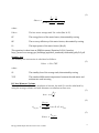
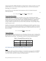
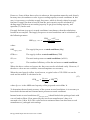
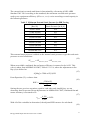
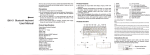
E MIT (Energy Model Input Translator) User’s Guide 1820 Folsom Street | Boulder, CO 80302 303.245.1003 | www.rmi.org May 2011 1 ACKNOWLEDGEMENTS The Energy Mod el Input Translator w as d eveloped w ith fund ing from Rocky Mountain Institute’s Com m ercial Build ing Retrofit Initiative. The follow ing staff at Rocky Mountain Institute w ere involved in its d evelopm ent: Aaron Buys, Lead Developer Kend ra Tupper, Project Manager Ellen Franconi, Content Support Ad d itional thanks to: International Build ing Perform ance Sim ulation Association (IBPSA) Gail H am p sm ire, GBCI Fred Porter, Architectural Energy Corporation All other beta testers in the energy m od eling com m unity Copyright 2010-2011, Rocky Mountain Institute Energy Mod el Inp u t Pre-Processor User’s Gu id e 2 2 TABLE OF CONTENTS 1 ACKNOWLEDGEMENTS .......................................................................................... 2 2 TABLE OF CONTENTS.............................................................................................. 3 3 OVERVIEW ............................................................................................................... 4 4 3.1 COMPATIBILITY AND SAVING THE FILE............................................................................... 4 3.2 O THER TOOLS AND M ATERIALS ....................................................................................... 4 TOOL COMPONENTS.............................................................................................. 5 4.1 LIGHTING, POWER & O CCUPANT D ENSITY CALCULATOR.................................................... 5 4.2 D OMESTIC H OT W ATER CALCULATOR.............................................................................. 7 4.2.1 Tank UA-Value Calculator ........................................................................................................ 7 4.2.2 Hot Water Use Estimator .......................................................................................................... 9 4.2.3 Input Power & Storage Capacity Estimator ................................................................................ 9 4.3 4.3.1 Proposed Case........................................................................................................................ 11 4.3.2 Baseline Case ......................................................................................................................... 11 4.4 PROPOSED SYSTEM FAN POWER & EFFICIENCY CALCULATOR..............................................11 4.4.1 Fan Power Calculations .......................................................................................................... 12 4.4.2 Compressor COP Calculation ................................................................................................. 13 4.5 BASELINE SYSTEM FAN POWER & EFFICIENCY CALCULATOR ................................................16 4.5.1 Fan Power Calculations .......................................................................................................... 17 4.5.2 Compressor COP Calculation ................................................................................................. 19 4.6 5 COOLING TOWER FAN EFFICIENCY CALCULATOR ..............................................................10 SCHEDULE CREATOR AND EXPORTER ...............................................................................21 4.6.1 eQuest Schedule Output ........................................................................................................ 21 4.6.2 EnergyPlus Schedule Output .................................................................................................. 22 REFERENCES........................................................................................................... 22 Energy Mod el Inp u t Pre-Processor User’s Gu id e 3 3 O VERVIEW This softw are tool is a com pilation of spread sheet based calculators that w ere d eveloped in response to the build ing energy m od eling com m unity’s need for tools that translate d esign d ata and cod e requirem ents into typical energy m od el inputs. The goal in d eveloping this tool is to red uce the tim e it takes to prod uce a quality energy m od el, and therefore increase the use and accuracy of energy m od eling in build ing analysis and d esign. 3.1 COMPATIBILITY AND SAVING THE FILE The tool w as d eveloped in Microsoft Wind ow s XP SP3 u sing Office 2007. The file has been saved d ow n to Excel 97-2003 com patibility to provid e greater usability. All efforts have been m ad e to avoid com patibility errors, but becau se the program uses VBA sub routines, problem s m ay occur d ue to library locations. These problem s occur w hen Excel is upd ated and the path of a VBA library is changed . This can be fixed by correcting the path by going to the VBA ed itor (Alt+F11), choosing Tools/ References, selecting the library which has been m od ified and brow sing to find the correct path. Ad d itionally, w hen using Excel 2007, the w orkbook m ust continue to be saved as 972003 com patible (.xls) as opposed to a 2007 version (.xlsx). 3.2 O THER TOOLS AND M ATERIALS This tool w as d eveloped by Rocky Mountain Institute (RMI) in conju nction w ith several other softw are tools and ed ucational m aterials w ith the sam e goal in m ind . This includ es: Model Manager: A DOE-2.2 based Excel tool, w hich stream lines param etric runs in DOE-2.2 based m od eling softw are LCCAid: A tool for life cycle cost analysis m ad e specifically for architects and build ing system s engineers. Elements: A freely available, com prehensive, integrated w eather tool suitable for solving all of the com m on w eather tasks associated w ith bu ild ing energy m od eling. Features includ e read / w rite/ convert betw een all m ajor w eather file form ats and cu stom d ata, visualization and analysis, d ata ed iting and error checking. Energy Audit Sample Forms: Sam ple form s to assist build ing energy aud itors in collecting the d ata required to com plete com prehensive energy and financial analyses of proposed m od ifications to a build ing EMIT and other tools and content can be found at: http:/ / w w w .rm i.org/ rm i/ Mod elingTools. Energy Mod el Inp u t Pre-Processor User’s Gu id e 4 4 TOOL COMPONENTS EMIT is m ad e up of six separate com ponents: 1. 2. 3. 4. 5. 6. Lighting, Pow er & Occupant Density Calculator Dom estic H ot Water Calculator Cooling Tow er Fan Efficiency Calcu lator Proposed System Fan Pow er & Efficiency Calculator Baseline System Fan Pow er & Efficiency Calculator Sched ule Creator and Exporter Each com ponent is d escribed in d etail below . 4.1 LIGHTING, POWER & O CCUPANT D ENSITY CALCULATOR The lighting, pow er and occupant d ensity calculator takes inform ation about energy m od el therm al zone space types and d eterm ines baseline values lighting pow er d ensity, receptacle pow er d ensity, occupant d ensity and occupant heat gain. The baseline values are taken from ASH RAE 90.1-2007 and the 2005 California ACM Manual (Title 24). Intent The intent of the m anager is to autom atically d eterm ine and organize baseline values based on a m ix of space types for the follow ing categories: Lighting Pow er Density Receptacle Pow er Density Occupant Density Occupant H eat Gain This tool can help energy m od elers organize and com pare large am ounts of info rm ation on internal gains. Early in the d esign, concep tual energy m od els often includ e large zones w hich are a m ix of a few space types – this tool allow s a w eighted average of internal gains to be d eterm ined , and d ocum ented for future review and revision. While som e energy m od eling w izard s allow for sim ilar w eighted averages to be created , they d o not accou nt for occupancy sensor cred its or d ocum ent the percentage breakdow n of space types for future revision. D irections To begin, click the “Ad d Zone” button and the follow ing form appears: Energy Mod el Inp u t Pre-Processor User’s Gu id e 5 Figure 1. Lighting, receptacle and occupant density calculator input form. Enter the zone nam e and any notes. Select the zone space type(s) and enter the percentage of the zone taken up by that space type. Multiple space types are allow ed to account for therm al zones that com bine d ifferent spaces; for exam ple, an open office next to a lobby and corrid or area all w ithin the core of a build ing. N ext, enter the proposed values for lighting and receptacle pow er d ensity, or select the “Use Baseline Value” checkbox. The proposed value entries are given for convenience so that the user can com pare the proposed and baseline values. They are not used in any calculations. To finish, click “OK” and the tool creates a new line in the spread sheet for the new zone. To ed it the zone values, the user can d irectly change the cell d ata or use the “Ed it Zone” button to bring up the sam e form and ed it values from there. To d elete a zone, click “Delete Zone” and the select the zone to be d eleted . Additional N otes Energy Mod el Inp u t Pre-Processor User’s Gu id e 6 The first zone in the sp read sheet is locked so that subsequent zones can be copied from it. Sched ules: When u sing d efault baseline valu es from sources su ch as ASH RAE 90.1 and Title 24, be su re to use the correspond ing fraction use sched ules from these sources as w ell. ASH RAE 90.1 sched ules can be fou nd in the Sched ule Lookup tab, and Title 24 sched ules can be found in the 2005 California ACM Manual. 4.2 D OMESTIC H OT W ATER CALCULATOR Intent Energy m od elers often struggle to translate cod e specifications and m anufacturer’s d ata into energy m od el inputs for d om estic hot w ater. The purpose of this spread sheet calculator is to brid ge that gap and d eterm ine ASH RAE 90.1-2007 baseline hot w ater heater full flow rate, efficiency and tank heat loss, and calculate these sam e values using m anufacturer's d ata for proposed w ater heaters. The calcu lators in this spread sheet can also be used to estim ate w ater heater perform ance w hen d esign d ata is unavailable. D irections When all d esign d ata is available, the calculations are sim ple. Enter the required d esign d ata for the proposed system as ind icated by d ark blue cells (includ ing the sched ule to the right), then enter the auto-sized values for the baseline system , and the spread sheet calculates the efficiencies, tank UA-value and full flow rate GPMs. The tank UA-value can be d ifficult to find on m anufacturer’s cutsheets, so a calculator is provid ed to help the user d eterm ine an appropriate value. 4.2.1 Tank UA-Value Calculator Tank UA-Value is the rate at w hich heat is lost from the stored hot water as a function of the tem perature d ifferential betw een the w ater and the air surround ing the tank. The units of Tank UA are Btu/ h-°F. To use the UA-value calculator, the user w ill need to have one of three sets of d esign values for the proposed system : Energy Factor & Recovery Efficiency; Stand by Loss; or Tank Diam eter & R-value. The calculator contains links to the AH RI d atabase of resid ential and com m ercial w ater heater test results, so if the proposed m od el num ber is available, this d ata can be looked up. If this d ata is unavailable, the user m ay estim ate values based on the typical values listed at the bottom of the calculator. A good sanity check is that the UA-value of the proposed tank is less than that of the baseline. Energy Factor-Recovery Efficiency The energy factor-recovery efficiency calculation uses the follow ing equation to d eterm ine tank UA: Energy Mod el Inp u t Pre-Processor User’s Gu id e 7 𝑈𝐴𝑡𝑎𝑛𝑘 1 1 − 𝑅𝐸 𝐸𝐹 = 24 1 67.5 × 41094 − 𝑅𝐸 × 𝑃 𝑖𝑛 (1) w here 𝑈𝐴𝑡𝑎𝑛𝑘 The hot w ater storage tank UA-value (Btu/ h-°F) 𝐸𝐹 The energy factor of the water heater, determined by testing 𝑅𝐸 The recovery efficiency of the water heater, determined by testing 𝑃𝑖𝑛 The input power of the water heater (Btu/h) This equation is taken from an EERE document (Equation D-2.14) found at: http://www1.eere.energy.gov/buildings/appliance_standards/residential/pdfs/D-2.pdf Standby Loss The stand by loss conversion is calcu lated as follow s: (2) 𝑈𝐴𝑡𝑎𝑛𝑘 = 𝑆𝐿 × 70℉ w here 𝑆𝐿 The standby loss of the storage tank, determined by testing 70℉ The standard differential temperature between the tank water and ambient air used in testing R-Value/D iameter/Volume When the R-value of the tank insulation is know n, the tank UA can be calcu lated by using the storage volum e and tank d iam eter to calculate surface area: 𝐴𝑏𝑎𝑠𝑒 = 𝜋 𝐴𝑠𝑢𝑟𝑓𝑎𝑐𝑒 = 𝑉𝑠𝑡𝑜𝑟𝑎𝑔𝑒 7.48[𝑔𝑎𝑙 ] 𝑓𝑡 3 𝐴𝑏𝑎𝑠𝑒 𝑈𝐴𝑡𝑎𝑛𝑘 Energy Mod el Inp u t Pre-Processor User’s Gu id e 𝐷 2 2 (3) (4) × 𝜋 × 𝐷 + 2 × 𝐴𝑏𝑎𝑠𝑒 𝐴𝑠𝑢𝑟𝑓𝑎𝑐𝑒 = 𝑅 (5) 8 w here 𝐴𝑏𝑎𝑠𝑒 The area of the base of a cylind rical tank (ft 2) 𝐷 The d iam eter of a cylind rical tank (ft) 𝐴𝑠𝑢𝑟 𝑓𝑎𝑐𝑒 The total surface area of a cylind rical tank (ft 2) 𝑉𝑠𝑡𝑜𝑟𝑎𝑔𝑒 The tank storage volum e (gal) 𝑅 The R-value of the tank insulation (h-°F-ft 2/ Btu) When d esign d ata is not available, proposed values m ay be estim ated using the H ot Water Use Estim ator and Input Pow er & Storage Capacity Estim ator. 4.2.2 Hot Water Use Estimator The hot w ater use estim ator takes the build ing type and cond itioned area and estim ates the num ber of occupants and hot w ater use per occupant per d ay to get a total baseline usage per d ay. The user can then d e-rate that baseline by a percentage to estim ate the proposed usage. The occupant d ensity for each build ing type is taken from the 2005 California ACM, and hot w ater use is taken from COMN ET Append ix B, Table 5. This calculation is a rough estim ate, and should only be used w hen no d esign d ata is available. 4.2.3 Input Power & Storage Capacity Estimator The input pow er and storage capacity estim ator uses build ing type and area to calculate peak hot w ater use and storage capacity. All calculated load s assu m e a 90°F d ifferential betw een inlet and outlet w ater tem peratures, w hich is based on typical d esign values of 50°F inlet and 140°F outlet. Ad d itionally, a 20% safety factor is applied to all calculations (as evid enced by the first num ber in the equation being 1.2). The calculation of inpu t pow er varies d epend ing on w hether the proposed system is an instantaneous system or storage system . Instantaneous Water Heater The instantaneous w ater heater calculation assum es no storage is used and the peak instantaneous load is required to be m et by the w ater heater. Peak load is d eterm ined by calculating the total num ber of hot w ater fixture units in the build ing and converting that to a hot w ater flow rate using the m od ified H unter curve. Fixture unit num bers are Energy Mod el Inp u t Pre-Processor User’s Gu id e 9 taken from the 2007 ASH RAE H and book of Applications, Chapter 49, Table 16, and the m od ified H unter curve can be found , am ong other places, in the 2003 International Plum bing Cod e, Table E103.3. Once the flow rate is d eterm ined , the instantaneous load is calculated using the follow ing equation: (6) 𝑃𝑖𝑛 = 1.2 × 8.33 𝐵𝑡𝑢 −𝑔𝑎𝑙 × 60 𝑚𝑖𝑛 × 𝐺𝑃𝑀 × 90℉ Storage Type Water Heater Storage type w ater heaters utilize stored hot w ater to shave peak load s and red uce required input pow er significantly relative to instantaneous w ater heaters. Calculations for this type of system are taken from the 2007 ASH RAE H and book of Applications, Chapter 49, pages 49.15 through 49.19. Figures 16 through 23 of the H and book give average values for required recovery rates in GPH / person and correspond ing storage capacity in gal/ person. N um bers of occu pants is calculated based on build ing area, and the required recovery flow rate and storage capacity are d eterm ined by m ultiplying the num ber of occupants by the factors taken from the H and book. Input pow er is then calculated from recovery flow rate (GPH ): (7) 𝐵𝑡𝑢 𝑃𝑖𝑛 = 1.2 × 8.33 −𝑔𝑎𝑙 × 𝐺𝑃𝐻 × 90℉ Thermal Efficiency Once storage capacity and input pow er are d eterm ined , the input pow er is ad justed for therm al efficiency based on th e type of fuel and w hether the user chooses a stand ard or high efficiency w ater heater. The follow ing values are used for therm al efficiency: Table 1. Thermal Efficiency by Fuel Type Fuel Type Electric N atural Gas Oil Stand ard Efficiency 0.98 0.80 0.78 H igh Efficiency 0.98 0.95 0.93 4.3 COOLING TOWER FAN EFFICIENCY CALCULATOR Intent The purpose of this sp read sheet calculator is to d eterm ine the proposed and ASH RAE 90.1-2007 baseline cooling tow er fan efficiency and express that efficiency in various w ays that m ay be required by energy m od eling program s. Energy Mod el Inp u t Pre-Processor User’s Gu id e 10 4.3.1 Proposed Case The proposed case requires the user to input the type of fan (axial or centrifugal), nam eplate horsepow er, cond enser w ater flow and cond enser w ater tem perature d ifference. The calculations assum e id eal cond enser w ater properties of 8.33 Btu/ gal-°F and that the full nam eplate horsepow er is equal to the brake horsepow er. This assum ption is not id eal, but ASH RAE 90.1-2007 d oes not d ifferentiate nam eplate from brake horsepow er for cooling tow ers. 4.3.2 Baseline Case The baseline case is based on ASH RAE 90.1-2007 Table 6.8.1G. The only required input for the baseline case is cond enser w ater flow rate as ASH RAE 90.1-2007 specifies that the baseline cooling tow er w ill have an axial fan. The sam e assum p tions are m ad e as in the proposed case, and the COP of the baseline is calculated . The COP is not actually d epend ent on the cond enser flow rate, but the calculations are show n for inform ational purposes. 4.4 PROPOSED SYSTEM FAN POWER & EFFICIENCY CALCULATOR Intent The proposed system calcu lator d eterm ines fan pow er for supply, return and exhaust fans, and it calculates com pressor coefficient of perform ance (COP) and energy input ratio (EIR). Many of the user inputs for the proposed system inform the calculations for the baseline fan pow er on the subsequent tab (Though, this inform ation transfer is not autom atic. The user m ust m anually inp ut these values in the baseline system tab). Ad d itionally, this calculator helps a user break out fan pow er and com pressor efficiency for their proposed packaged units. The spread sheet uses form s for d ata input. Energy Mod el Inp u t Pre-Processor User’s Gu id e 11 D irections To begin, click “Ad d System ” and the follow ing form appears: Figure 2. Proposed system input form. The user m u st enter a nam e and then m u st check off all options that apply. As the options are checked off, further inputs w ill appear as necessary. The only inputs required regard less of options are supply fan pow er and airflow . 4.4.1 Fan Power Calculations The fan pow er calculations are fairly straightforw ard . The user enters the fan pow er (kW) and airflow (CFM) for each fan category (supply, return and exhaust), and the spread sheet calculates the kW/ CFM. This calculation is not d ifficult, but som etim es d eterm ining the fan pow er can be a challenge, so a fan pow er calculator has been includ ed . This calcu lator takes the CFM, total static pressure, fan and m otor efficiencies and calculates fan pow er in kilow atts. This calculator is accessed by clicking the button located in the low er right hand corner of the form . Energy Mod el Inp u t Pre-Processor User’s Gu id e 12 It is critical to assign the fan pow er and CFM for the proposed system appropriately. The follow ing d efinitions serve as a guid e for this purpose. Supply Fan Pow er: Includ es supply fan pow er for m ain air hand lers or rooftop units, as w ell as any d ed icated outsid e air system s (DOAS). Do N OT inclu d e fan pow ered boxes, no m atter w hat their configuration is. Return Fan Pow er: Includ es both return fans, w hich have the sam e sched ule as su pply fans, and relief fans, w hich run only d uring econom izer m od e to relieve the build ing of excess pressure d ue to increased outsid e air quantities. Exhaust Fan Pow er: Includ es all fans that exhaust build ing air to the outd oors. 4.4.2 Compressor COP Calculation If the user clicks DX Cooling as a system option, several input boxes appear because t he m ost com plicated calculation for the proposed system is com pressor COP. The m ethod for calculating this value is taken from ASH RAE 90.1-2007 User’s Manual, equations (GA) through (G-C). These equations relate EER to COP and are as follow s: (8) 𝐵𝑡𝑢 𝑁𝑒𝑡 𝐶𝑜𝑜𝑙𝑖𝑛𝑔 [𝐵𝑡𝑢 ] (𝐺𝑟𝑜𝑠𝑠 𝐶𝑜𝑜𝑙𝑖𝑛𝑔 − 𝑆𝑢𝑝𝑝𝑙𝑦 𝐹𝑎𝑛 𝑃𝑜𝑤𝑒𝑟) [ ] 𝐸𝐸𝑅 = = 𝑇𝑜𝑡𝑎𝑙 𝐼𝑛𝑝𝑢𝑡 𝑃𝑜𝑤𝑒𝑟 [𝑊] 𝑇𝑜𝑡𝑎𝑙 𝐼𝑛𝑝𝑢𝑡 𝑃𝑜𝑤𝑒𝑟 [𝑊] (9) 𝐵𝑡𝑢 𝐺𝑟𝑜𝑠𝑠 𝐶𝑜𝑜𝑙𝑖𝑛𝑔 𝐶𝑎𝑝𝑎𝑐𝑖𝑡𝑦 [ ] 𝐶𝑂𝑃 = 𝐶𝑜𝑚𝑝𝑟𝑒𝑠𝑠𝑜𝑟 𝑃𝑜𝑤𝑒𝑟 − 𝐶𝑜𝑛𝑑𝑒𝑛𝑠𝑒𝑟 𝐹𝑎𝑛 𝑃𝑜𝑤𝑒𝑟 [𝑊] × 3.413[𝑊𝐵𝑡𝑢− ] 𝐺𝑟𝑜𝑠𝑠 𝐶𝑜𝑜𝑙𝑖𝑛𝑔 𝐶𝑎𝑝𝑎𝑐𝑖𝑡𝑦 [𝐵𝑡𝑢 ] 𝐶𝑂𝑃 = 𝑇𝑜𝑡𝑎𝑙 𝐼𝑛𝑝𝑢𝑡 𝑃𝑜𝑤𝑒𝑟 − 𝑆𝑢𝑝𝑝𝑙𝑦 𝐹𝑎𝑛 𝑃𝑜𝑤𝑒𝑟 [𝑊] × 3.413[𝑊𝐵𝑡𝑢− ] (10) N ote that all values are at AH RI rated cond itions. Do not use actual d esign cond itions, because COP inputs to energy m od els generally are at rated cond itions and COP for specific cond itions in the sim ulation are calcu lated from rated cond itions based on part load curves. There are tw o w ays to calculate COP from EER in this tool. The sim plest w ay is to use EER, net cooling capacity and gross cooling capacity. This w ay w e can solve for supply fan pow er and total input pow er using equation (8) and plug those values into equation (10). Com bining and sim plifying these tw o equations results in the follow ing equation for COP: (11) 𝐺𝑟𝑜𝑠𝑠 𝐶𝑜𝑜𝑙𝑖𝑛𝑔 𝐶𝑎𝑝𝑎𝑐𝑖𝑡𝑦 [𝐵𝑡𝑢 ] 𝐶𝑂𝑃 = 𝐵𝑡𝑢 3.413 𝑊 − 1+ × 𝑅𝑎𝑡𝑒𝑑 𝐶𝑜𝑜𝑙𝑖𝑛𝑔 𝐵𝑡𝑢 − 𝐺𝑟𝑜𝑠𝑠 𝐶𝑜𝑜𝑙𝑖𝑛𝑔 [𝐵𝑡𝑢 ] 𝐸𝐸𝑅 Energy Mod el Inp u t Pre-Processor User’s Gu id e 13 H ow ever, if one of these three values is unknow n, this equation cannot be used d irectly. In m any cases, the unknow n value is gross cooling capacity at rated cond itions. In this case, it is necessary to calculate supply fan p ow er, w hich is d irectly related to supply fan heat. If supply fan heat is know n, then the gross capacity can be calculated by ad d ing supply fan heat to net cooling capacity to get gross cooling capacity, and equation (11) can be u sed . If supply fan heat (or pow er) at rated cond itions is not know n, then the calculations becom e m ore com plex. The supply fan pow er at rated cond itions can be calculated in the follow ing m anner: (12) 𝐶𝐹𝑀𝑟𝑎𝑡𝑒𝑑 × 𝑆𝑃𝑡,𝑟𝑎𝑡𝑒𝑑 𝐵𝐻𝑃𝑠𝑢𝑝𝑝𝑙𝑦 ,𝑟𝑎𝑡𝑒𝑑 = −𝑖𝑛 𝐻2𝑂 6,356[𝐶𝐹𝑀 𝑏 ] × 𝜂𝑓𝑎𝑛 𝑝 w here 𝐵𝐻𝑃𝑠𝑢𝑝𝑝𝑙𝑦 ,𝑟𝑎𝑡𝑒𝑑 The supply fan pow er at rated conditions (bhp) 𝐶𝐹𝑀𝑟𝑎𝑡𝑒𝑑 The supply airflow at rated conditions (CFM) 𝑆𝑃𝑡,𝑟𝑎𝑡𝑒𝑑 The total static pressure at rated conditions (in H 2O) 𝜂𝑓𝑎𝑛 The com bined efficiency of the fan and m otor at rated conditions Where the above values are know n, the fan pow er can be calcu lated easily. H ow ever, if the above values are not available, som e assu m ptions are necessary. When the rated supply airflow is not know n, a typical value of 350 CFM/ ton can be used and the airflow is calculated to be: 𝐶𝐹𝑀𝑟𝑎𝑡𝑒𝑑 = 𝑄𝑡,𝑟𝑎𝑡𝑒𝑑 12 𝑘𝐵𝑡𝑢 −𝑡𝑜𝑛 (13) × 𝐶𝐹𝑀 350[ 𝑡𝑜𝑛 ] w here 𝑄𝑡,𝑟𝑎𝑡𝑒𝑑 is the AH RI rated capacity of the proposed unit in kBtu/ h. To d eterm ine the total static pressure of the system at rated cond itions, it is necessary to know both the internal and external static pressures at rated cond itions. Internal static at rated cond itions (𝑆𝑃𝑖𝑛𝑡𝑒𝑟𝑛𝑎𝑙 ,𝑟𝑎𝑡𝑒𝑑 ) should includ e the packaged unit w ith w et coil and no filters. If not entered by the user from m anufacturer’s d ata, it is assum ed to be 1.00 in. H 2O. This value has been estim ated based on d ata from several m anufacturers’ packaged unit catalogs. Energy Mod el Inp u t Pre-Processor User’s Gu id e 14 The external static at rated cond itions is d eterm ined by referencing AN SI/ AH RI Stand ard 340/ 360. Accord ing to the stand ard , the m inim um external static pressure used to rate equipm ent efficiency (𝑆𝑃𝑒𝑥𝑡𝑒𝑟𝑛𝑎𝑙 ,𝑟𝑎𝑡𝑒𝑑 ) varies accord ing to rated capacity in the follow ing m anner: Table 2. Minimum External Static Pressure for EER Testing Rated Capacity Minim um External [Btu/ hr] Static Pressure [in H 2O] 65,000-70,000 0.20 71,000-105,000 0.25 106,000-134,000 0.30 135,000-210,000 0.35 212,000-280,000 0.40 282,000-350,000 0.45 352,000-400,000 0.55 405,000-500,000 0.65 505,000 and over 0.75 This external static pressure is ad d ed to the internal static pressure to get the total static pressure at rated cond itions. (14) 𝑆𝑃𝑡,𝑟𝑎𝑡𝑒𝑑 = 𝑆𝑃𝑖𝑛𝑡𝑒𝑟𝑛𝑎𝑙 ,𝑟𝑎𝑡𝑒𝑑 + 𝑆𝑃𝑒𝑥𝑡𝑒𝑟𝑛𝑎𝑙 ,𝑟𝑎𝑡𝑒𝑑 When unavailable, com bined fan and m otor efficiency is assum ed to be 0.650. This value is taken from ASH RAE 90.l-2007, Table 6.5.3.1.1A, w here the ad justm ent to fan bhp (A ) is d efined as: (15) 𝐴 [𝑏𝑝] = 𝐶𝐹𝑀𝐷 × 𝑃𝐷/4,131 From Equation (12), w e know that: 𝐶𝐹𝑀 × 𝑃𝐷 𝐵𝐻𝑃 = −𝑖𝑛 𝐻2𝑂 6,356[𝐶𝐹𝑀 𝑏 ] × 𝜂𝑓𝑎𝑛 𝑝 (16) Setting the tw o previous equations equal to each other and sim plifying, w e can d eterm ine that for pressure d rop ad justm ents in ASH RAE 90.1-2007, com bined fan and m otor efficiency is assum ed to be: (17) 4,131 𝜂𝑓𝑎𝑛 = = 0.650 6,356 With all of the variables in d eterm ined , the ad justed EER can now be calculated : (18) Energy Mod el Inp u t Pre-Processor User’s Gu id e 15 𝐸𝐸𝑅𝑎𝑑𝑗 = 𝑄𝑡,𝑟𝑎𝑡𝑒𝑑 + 𝑄𝑓𝑎𝑛 ,𝑟𝑎𝑡𝑒𝑑 𝑄𝑡,𝑟𝑎𝑡𝑒𝑑 𝐸𝐸𝑅 − 𝑃𝑓𝑎𝑛 ,𝑟𝑎𝑡𝑒𝑑 w here 𝐸𝐸𝑅𝑎𝑑𝑗 The ad ju sted Energy Efficiency Ratio for calculation purposes (Btu/ W-h) 𝐸𝐸𝑅 The rated Energy Efficiency Ratio (Btu/ W-h) 𝑘𝐵𝑡𝑢 𝑄𝑓𝑎𝑛 ,𝑟𝑎𝑡𝑒𝑑 = 𝐵𝐻𝑃𝑠𝑢𝑝𝑝𝑙𝑦 ,𝑟𝑎𝑡𝑒𝑑 × 2.545[ −𝑏𝑝 ] The fan heat at rated cond itions (kBtu/ h) 𝑘𝑊 𝑃𝑓𝑎𝑛 ,𝑟𝑎𝑡𝑒𝑑 = 𝐵𝐻𝑃𝑠𝑢𝑝𝑝𝑙𝑦 ,𝑟𝑎𝑡𝑒𝑑 × 0.7457[𝑏 ] 𝑝 The fan pow er at rated cond itions (kW) Com pressor COP is then calculated as follow s: 𝐶𝑂𝑃𝑐𝑜𝑚𝑝 = 𝐸𝐸𝑅𝑎𝑑𝑗 (19) 𝐵𝑡𝑢 3.413[𝑊− ] The energy input ratio (EIR) is the inverse of the calculated COP. 4.5 BASELINE SYSTEM FAN POWER & EFFICIENCY CALCULATOR The baseline system calculator is very sim ilar to the proposed system calculator in that it d eterm ines fan pow er (kW/ CFM) for supply, return and exhaust; and it calculates com pressor COP and EIR. To begin, click “Ad d System ” and the follow ing form appears: Energy Mod el Inp u t Pre-Processor User’s Gu id e 16 Figure 3. Baseline system input form. All inputs on the form are required , except if system s 7 or 8 are selected , cooling load is not required . If the 90.1 baseline system type is unknow n, the user can click on the Baseline System Type Selector and d eterm ine w hich baseline system is appropriate. 4.5.1 Fan Power Calculations The fan pow er calculations require the user to enter supply and exhaust CFM, as w ell as supply, return and exhaust fan ratios. Return CFM is calculated by subtracting exhaust from supply. Fan pow er ratios are used to d eterm ine how m uch of the allotted baseline fan pow er is used for each system . These ratios m ust be equal to the ratios of fan pow er in the proposed system . To calculate the ratios for the proposed system , sum up all fan pow er for each type (supply, return and exhaust) and d ivid e the sum by th e total fan pow er (equal to the sum of these three sum s). In the event that a proposed system fan serves Energy Mod el Inp u t Pre-Processor User’s Gu id e 17 therm al blocks covered by d ifferent baseline system s, the fan pow er m ust be d ivid ed betw een the baseline system s in proportion to proposed CFM. After all inputs have been d eterm ined , the allotted baseline fan pow er can be calcu lated . This calculation is d one per ASH RAE 90.1-2007 section G3.1.2.9. Ad justm ents to fan pow er are required to be review ed . When the “Go To Pressure Drop Ad justm ents” button is clicked , the follow ing form appears: Figure 4. Pressure drop adjustments input form. All applicable ad justm ent options should be checked and the appropriate airflow should be entered . Airflow is a required inpu t because the ad ju stm ent calculation only Energy Mod el Inp u t Pre-Processor User’s Gu id e 18 accounts for the airflow passing through the d evice, not the total supply airflow . The applicable section of ASH RAE 90.1-2007 is show n for reference. 4.5.2 Compressor COP Calculation Com pressor COP for baseline system s can be calculated in a sim ilar m anner to the proposed system calcu lations as outlined in equations (12) through (19), except that instead of manufacturer’s d ata, the values listed as assum ptions in the proposed system d escription are used , and the baseline EER is d eterm ined from the rated capacity and ASH RAE 90.1-2007 Tables 6.8.1A & B. The assum ptions m ad e are: 1. Com bined fan/ m otor efficiency (𝜂𝑓𝑎𝑛 ) of 0.650 2. Rated airflow of 350 CFM/ ton. So, if w e return to equations (18) and (19) and com bine them , w e get: 𝑄𝑡,𝑟𝑎𝑡𝑒𝑑 + 𝑄𝑓𝑎𝑛 ,𝑟𝑎𝑡𝑒𝑑 𝐶𝑂𝑃 = 𝑄𝑡,𝑟𝑎𝑡𝑒𝑑 3.413 𝐸𝐸𝑅 − 𝑃𝑓𝑎𝑛 ,𝑟𝑎𝑡𝑒𝑑 (20) We also know that (21) 𝑄𝑓𝑎𝑛 ,𝑟𝑎𝑡𝑒𝑑 𝑃𝑓𝑎𝑛 ,𝑟𝑎𝑡𝑒𝑑 = 𝐵𝑡𝑢 3.413[𝑊− ] So, if w e substitute for 𝑃𝑓𝑎𝑛 ,𝑟𝑎𝑡𝑒𝑑 and sim plify, then w e find that 𝑄𝑡,𝑟𝑎𝑡𝑒𝑑 + 𝑄𝑓𝑎𝑛 ,𝑟𝑎𝑡𝑒𝑑 𝐶𝑂𝑃 = 𝑄𝑡,𝑟𝑎𝑡𝑒𝑑 3.413 𝐸𝐸𝑅 − 𝑄𝑓𝑎𝑛 ,𝑟𝑎𝑡𝑒𝑑 (22) If w e take equation (12) for fan pow er and convert from brake horsepow er to kBtu/ h, then w e get 𝑄𝑓𝑎𝑛 ,𝑟𝑎𝑡𝑒𝑑 = 𝐶𝐹𝑀𝑟𝑎𝑡𝑒𝑑 × 𝑆𝑃𝑡,𝑟𝑎𝑡𝑒𝑑 2,496 𝐶𝐹𝑀 −𝑖𝑛 𝐻2𝑂− 𝑘𝐵𝑡𝑢 (23) × 𝜂𝑓𝑎𝑛 N ow , if w e substitute the tw o assum ptions from above (350 CFM/ ton and 0.65 com bined fan and m otor efficiency), then w e get 𝑄𝑓𝑎𝑛 ,𝑟𝑎𝑡𝑒𝑑 = 𝑄𝑡,𝑟𝑎𝑡𝑒𝑑 × 350[𝐶𝐹𝑀 ] × 𝑆𝑃𝑡,𝑟𝑎𝑡𝑒𝑑 𝑘𝐵𝑡𝑢 𝑡𝑜𝑛 12 −𝑡𝑜𝑛 2,496 𝐶𝐹𝑀 −𝑖𝑛 𝐻 2𝑂− 𝑘𝐵𝑡𝑢 Energy Mod el Inp u t Pre-Processor User’s Gu id e × 0.65 (24) = 𝑄𝑡,𝑟𝑎𝑡𝑒𝑑 × 𝑆𝑃𝑡,𝑟𝑎𝑡𝑒𝑑 55.615 [𝑖𝑛 𝐻2 𝑂] 19 N ow , if w e substitute for 𝑄𝑓𝑎𝑛 ,𝑟𝑎𝑡𝑒𝑑 in equation (22) w e get: 𝑄𝑡,𝑟𝑎𝑡𝑒𝑑 × 𝑆𝑃𝑡,𝑟𝑎𝑡𝑒𝑑 𝑆𝑃𝑡,𝑟𝑎𝑡𝑒𝑑 𝑄𝑡,𝑟𝑎𝑡𝑒𝑑 1 + 55.615 [𝑖𝑛 𝐻2 𝑂] 55.615 [𝑖𝑛 𝐻2 𝑂] 𝐶𝑂𝑃 = = 𝑄𝑡,𝑟𝑎𝑡𝑒𝑑 𝑄𝑡,𝑟𝑎𝑡𝑒𝑑 × 𝑆𝑃𝑡,𝑟𝑎𝑡𝑒𝑑 𝑆𝑃𝑡,𝑟𝑎𝑡𝑒𝑑 3.413 3.413 𝐸𝐸𝑅 − 𝑄𝑡,𝑟𝑎𝑡𝑒𝑑 𝐸𝐸𝑅 − 55.615 [𝑖𝑛 𝐻2 𝑂] 55.615 [𝑖𝑛 𝐻2 𝑂] (25) 𝑄𝑡,𝑟𝑎𝑡𝑒𝑑 + and 𝑄𝑡,𝑟𝑎𝑡𝑒𝑑 d rops out to give us: 𝑆𝑃𝑡,𝑟𝑎𝑡𝑒𝑑 1+ 55.615 [𝑖𝑛 𝐻2 𝑂] 𝐶𝑂𝑃 = 𝑆𝑃𝑡,𝑟𝑎𝑡𝑒𝑑 3.413 𝐸𝐸𝑅 − 55.615 [𝑖𝑛 𝐻2 𝑂] (26) If w e d efine an arbitrary term X , as follow s, then the equation w ill be easier to read : (27) 𝑋= 𝑆𝑃𝑡,𝑟𝑎𝑡𝑒𝑑 55.615 [𝑖𝑛 𝐻2 𝑂] Su bstituting X in equation (26), w e get: 𝐶𝑂𝑃𝑏𝑎𝑠𝑒𝑙𝑖𝑛𝑒 = 1+𝑋 3.413 𝐸𝐸𝑅𝑚𝑖𝑛 ,90.1 − 𝑋 (28) Energy input ratio (EIR) is the inverse of COP. Going back to equation (27), 𝑆𝑃𝑡,𝑟𝑎𝑡𝑒𝑑 is the total static pressure d rop through the system at rated cond itions, w hich w e know from equ ation (14) is the sum of the internal and external static pressure d rops, so w hen com bined w ith equation (27), w e get (29) 𝑋= 𝑆𝑃𝑖𝑛𝑡𝑒𝑟𝑛𝑎𝑙 ,𝑟𝑎𝑡𝑒𝑑 + 𝑆𝑃𝑒𝑥𝑡𝑒𝑟𝑛𝑎𝑙 55.615 [𝑖𝑛 𝐻2 𝑂] ,𝑟𝑎𝑡𝑒𝑑 w here 𝑆𝑃𝑒𝑥𝑡𝑒𝑟𝑛𝑎𝑙 ,𝑟𝑎𝑡𝑒𝑑 The m inim um external static pressure specified in AN SI/ AH RI Stand ard 340/ 360 for the rated capacity of the baseline system , as show n in Table 1. 𝑆𝑃𝑖𝑛𝑡𝑒𝑟𝑛𝑎𝑙 ,𝑟𝑎𝑡 𝑒𝑑 The internal static pressure at rated cond itions. Energy Mod el Inp u t Pre-Processor User’s Gu id e 20 H ow ever, internal static is not governed by any stand ard , so it should be assum ed that internal static of the baseline system is equal to the internal static of the proposed system if there is a proposed system that correspond s to the baseline system . If there is no correspond ing proposed system or the internal static of the proposed system is unknow n, use the d efault value of 1.00 in H 2O. This value is estim ated from m anufacturers’ d ata on m any d ifferent packaged RTUs. The ASH RAE 90.1 com m ittee m ay d ecid e to stipulate a specific allow able internal static value for baseline system s in the future, w hich w ould obviously supersed e this value. One alternate solution to using the m ethod outlined above w ould be for ASH RAE 90.1 to set a baseline allow able fan heat, for exam ple at 3% of rated capacity. In this case, w e could use equation (22) to d irectly calculate COP: (30) 𝑄𝑡,𝑟𝑎𝑡𝑒𝑑 + 𝑄𝑓𝑎𝑛 ,𝑟𝑎𝑡𝑒𝑑 1.03 𝑄𝑡,𝑟𝑎𝑡𝑒𝑑 1.03 𝐶𝑂𝑃 = = = 3.413 3.413 3.413 𝐸𝐸𝑅 𝑄𝑡,𝑟𝑎𝑡𝑒𝑑 − 𝑄𝑓𝑎𝑛 ,𝑟𝑎𝑡𝑒𝑑 𝐸𝐸𝑅 𝑄𝑡,𝑟𝑎𝑡𝑒𝑑 − 0.03 𝑄𝑡,𝑟𝑎𝑡𝑒𝑑 𝐸𝐸𝑅 − 0.03 The above equation is fairly accurate relative to the com plex calculations required otherw ise. Assum ing an internal static of 1.00 in H 2O, the d ifference is betw een -0.6% to +3.8%. 4.6 SCHEDULE CREATOR AND EXPORTER Intent Energy m od elers often need to m anipulate or d eal w ith fraction al sched ule d ata outsid e of energy m od el program s. Translating this d ata into energy m od el sched ules can be extrem ely tim e consum ing, especially w hen d ealin g w ith 8760 d ata points. This sched ule creator and exporter prod uces eQuest input files (.inp) or EnergyPlus input d ata files (.id f) containing cod e language for m od eling sched ules. D irections To begin, click “Create Sched ule” and select the appropriate m od eling program . A form then appears w here the user can d efine the type of sched ule to be created . At the m om ent, only Annual 8760 sched ules are available for EnergyPlus. Many m ore options are available for eQuest. 4.6.1 eQuest Schedule Output eQuest sched ules m ay be created for a single d ay, w eek or year. When the type of sched ule is d eterm ined from the form , the appropriate input table w ill appear. The u ser can then enter the values. Depend ing on the sched ule type, lim its are placed on the acceptable values the u ser can enter in the table. Once d ata entry is com plete, the user clicks “Export Sched ule” and selects the d irectory to w hich they w ould like to save the Energy Mod el Inp u t Pre-Processor User’s Gu id e 21 sched ule. The sched ule is saved as an .inp file, w hich the u ser can im port using the “File/ Im port File…” com m and in eQuest. When a w eekly sched u le is m ad e in the .inp file, the follow ing assu m ptions are m ad e for the heating and cooling d esign d ay sched u les: Table 3. D esign D ay Schedule Assumption Weekly D esign D ay Schedule Type Assumption Weekly 5-2 Weekd ay Weekly 5-1-1 Weekd ay Weekly 7-d ay Mond ay Annual 8760 Mond ay The d esign d ay sched u les can only be changed m anually insid e the input file. See the eQuest d ocum entation for instructions on how to d o this. 4.6.2 EnergyPlus Schedule Output EnergyPlus sched u les are currently lim ited to Annual 8760 sched ules only. The sched ules are exported as “Sched ule:File” type sched ules w here an IDF file is created w ith the nam e and type of the sched ule, and a .csv file of the values is created and referenced by the IDF file. To copy the created sched ule to the sim ulation file, the user should open both the created IDF file and the sim ulation IDF file in the IDF Ed itor. In the sched ule file, scroll d ow n to the Sched ule:File object in the Class List w ind ow . Select the created sched ule and click the “Copy Obj” button. Move to the sim ulation file and go to the Sched ule:File class. Click the “Paste Obj” button, and the created sched ule w ill becom e part of the sim ulation file. 5 REFERENCES ASH RAE 90.1-2007 ASH RAE 90.1-2007 User’s Manual ASH RAE H and book-H VAC Applications California 2005 ACM Manual Energy Mod el Inp u t Pre-Processor User’s Gu id e 22