1
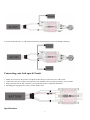
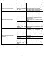
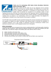
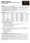
Thank you for purchasing Alien Power System Seal Series Brushless Electronic Speed Controller (ESC). This is a series of hight-end and high quality and good performance ESC. We all know that that boaters crave for more power than cars and airplanes and we have come up with a whole new way to put the power to the water – The new SEAL line water-cooling brushless speed controls for marine applications. This series of ESC also feature with good water cooling system, using state-of-art MOSFET, exposed finned sink. This is a pro-level product, please read the manual thoroughly before starting using it. Alien Electronics LTD have no control over the use, installation, application, or maintenance of these products, thus no liability shall be assumed nor accepted for any damages, losses of costs resulting from the use of this item. Any claims arising from the operating, failure or malfunctioning etc. will be denied. We assume no liability for personal injury, property damage or consequential damages resulting from our product or our workmanship. As far as is legally permitted, the obligation for compensation is limited to the invoice amount of the product in question. Safety Precautions ● ● ● ● ● ● ● ● ● ● ● ● ● ● Do not install the propeller (fixed wing) or drive pinion (helicopter) on the motor when you test the ESC and motor for the first time to verify the correct settings on your radio. Only install your propeller or pinion after you have confirmed that the settings on your radio is correct. Never use ruptured or punctured battery cells. Never use battery packs that are known to overheat. Never use short circuit battery or motor terminals. Always use proper insulation material for cable insulation. Always use proper cable connectors. Do not exceed the number of cells or servos specified by the ESC. Install the ESC in a suitable location with adequate ventilation for cooling. This ESC has a built-in over temperature cutoff protection feature that will immediately cut power to the motor once the ESC temperature exceeds the 230 Deg F/ 110 Deg C high temperature limit. Use only batteries that are supported by the ESC and ensure the correct polarity before connecting. Switch your Transmitter ON and ensure the throttle stick is in the minimum position before connecting the battery pack. Never switch your transmitter off while the battery is connected to your ESC. Only connect your battery pack just before flying and do not leave your battery pack connected after flying. Handle your model with extreme care once the battery pack is connected and keep away from the propeller at all times. Never stand in-line or directly in front of any rotating parts. Do not immerse the ESC underwater or allow it to get wet while powered up. Always fly at a designated flying site and abide by the rules and guidelines set by your flying club. Noted: Wrong battery polarity will damage the ESC and void the warranty. Wire Connection: 1. The speed controller can be connected to the motor by soldering directly or with high quality connectors. Always use new connectors, which should be soldered carefully to the cables and insulated with heat shrink tube. The maximum length of the battery pack wires shall be within 6 inches. Solder controller to the motor wires. Solder appropriate connectors to the battery wires. Insulate all solder connectors with heat shrink tubes. Plug the “JR” connector into the receiver throttle channel. Controller Red and Black wires connects to battery pack Red and Black wires respectively. 1. 1 2. For the OPTO HV ESC, we add antispark curcuit to protect the ESC person from damage and injury. Connecting your Anti-spark Circuit 1. 2. 3. 4. Solder an extra wire to the positive wire (Red) of the battery for sake of best use of the circuit Connect the extra wire with our anti-spark wire from the ESC before you plug your battery into your ESC Plug your batter into the ESC connector, you will find the spark is completely eliminated Do unplug the anti-spark wire before you take further steps. Specifications: 2 Type Cont.\Burst Battery cell BEC Weight Size (mm) User Current(A) NiXX/Lipo Output (g) W*L*H Program Seal 70A SBEC 3A 70A\90A 5-18NC/2-6Lipo 5.5V/3A 113 49*66*23 YES Seal 90A SBEC 3A 90A\110A 5-18NC/2-6Lipo 5.5V/3A 113 49*66*23 YES Seal 130A SBEC 3A 130A\150A 5-18NC/2-6Lipo 5.5V/3A 171 62*65*24 YES Seal 160A SBEC 3A 160A\180A 5-18NC/2-6Lipo 5.5V/3A 171 62*65*24 YES Seal 200A SBEC 3A 200A\300A 5-24NC/2-8Lipo 5.5V/3A 200 115*75*26 YES Seal 120A OPTO HV 120A\150A 18-38NC/6-12Lipo 5.5V/3A 125 62*65*24 YES Seal 150A OPTO HV 150A\180A 18-38NC/6-12Lipo 5.5V/3A 130 62*65*24 YES Features: 1. 2. 3. 4. 5. 6. 7. 8. 9. 10. High SBEC Current Output, continuous 3A and burst 5A, designed to meet your high current application Over-heat protection, low-voltage protection and lost-signal protection Secondary sub-menu setting by LCD program card or PC interface Firmware updating by PC interface Unique metal shape designing gives your new fashion visual impact. Super smooth and accurate throttle linearity Support and match with most of the motors, including high RPM motors Programmable motor timing Utilizes new smaller MOSFET technology to minimize weight Auto motor shut down if signal is lost or there is interference Throttle Calibration The Surpass ESC features Automatic Throttle Calibration to attain the smoothest throttle response and resolution throughout the entire throttle range of your transmitter. This step is done once to allow the ESC to “learn and memorize” your Transmitter’s throttle output signals and only repeated if you change your transmitter. 1. Switch your Transmitter ON and set the throttle stick to its maximum position. 2. Connect the battery pack to the ESC. Wait for about 2 seconds, the motor will beep for twice, then put the throttle in the minimum position, the motor will also beep, which indicates that your ESC has got the signal range of the throttle from your transmitter. Entering the programming Mode Turn on your radio and set the throttle stick to top positon (100%) ● Plug the battery pack into your controller ● Wait for 2 seconds, you will hear 4 groups of two sets of fast beeps, and after this you will hear four single beeps to indicate you have successfully entered the programming mode ● Selecting the Programmable Item The Programming items are arranged in Sequence, each Programmable Item is equivalent to an audible tone emitting for four times. You will hear 8 tones in a loop with the following sequence. When the desired tone for the Programmable Item 3 is reached, move the throttle stick down to its minimum position. The motor will emit one special tone confirming the desired programmable item has been entered. Selecting the Desired Value The motor has been emitting sequentially. If the desired value of the programmable item is reached, set the throttle stick to its maximum position. The motor will emit one special tone confirming the new setting is saved. Disconnecting the Battery If you don’t want to go on to programming, disconnect the battery pack directly. If you want to go on to programming, keep waiting to the next programmable item to select the value you need. Note: You could also select the LED program card to program your desired function. Program card is as the option spare part, its programming procedure is described in the LED program card user manual Programming Menu 1- Brake Type 1. Turn on your radio and set the throttle stick to top positon (100%) 2. Plug the battery pack into your controller 3. Wait for 2 seconds, you will hear 4 groups of two sets of fast beeps, after this you will hear single short beep indicates you are at Brake menu, you will hear this beep four times please make choice before it enters into next selection. 4. Then pull the throttle stick to minimum position, you will hear a music tone to confirm you enter into the Brake sub-menu 5. Brake type options will be indicated in beeps in sequence (For beeps code please refer to “The Tones Sequence and Code”) 6. Move your stick to top position when you hear the desired option, then you will hear a music tone to confirm that you have set your brake type and saved. 7. You will enter into next menu after short moment for further settings; or unplug the battery to exit the programmable mode. Programming Menu 2- Battery Type 1. Turn on your radio and set the throttle stick to top positon (100%) 2. Plug the battery pack into your controller 3. Wait for 2 seconds, you will hear 4 groups of two sets of fast beeps, after this you will hear 2 short beeps indicates you are at Battery menu. You will hear this beep four times please make choice before it enters into next selection. 4. Then pull the throttle stick to minimum position, you will hear a music tone to confirm you enter into the Battery Type sub-menu 5. Battery type options will be indicated in beeps in sequence (For beeps code please refer to “The Tones Sequence and Code”) 6. Move your stick to top position when you hear the desired option, then you will hear a music tone to confirm that you have set your brake type and saved. 7. You will enter into next menu after short moment for further settings; or unplug the battery to exit the programmable mode. Programming Menu 3- Voltage Cutoff Threshold 2.8V/50%/ 3.0V/60%/ 3.2V/65%/No Protection 1. Turn on your radio and set the throttle stick to top positon (100%) 2. Plug the battery pack into your controller 3. Wait for 2 seconds, you will hear 4 groups of two sets of fast beeps, after this you will hear 3 short beeps indicates you are at Voltage Cutoff Threshold menu. You will hear this beep four times please make choice before it enters into next selection. 4. Then pull the throttle stick to minimum position, you will hear a music tone to confirm you enter into the Voltage Cutoff Threshold sub-menu 4 5. Voltage Cutoff Threshold will be indicated in beeps in sequence (For beeps code please refer to “The Tones Sequence and Code”) 6. When you hear the desired option move your stick to top position, then you will hear a music tone to confirm that you have set your Voltage Cutoff Threshold and saved. 7. You will enter into next menu after short moment for further settings; or unplug the battery to exit the programmable mode Note: 1) For Li-xx packs- number of cells are automatically calculated and requires no user input apart from defining the battery type. This ESC provides 4 setting options for the low voltage protection threshold; 2.8V/ 3.0V/3.2V/No Protection. For example: the voltage cutoff options for an 11.1V/ 3 cell Li-Po pack would be 8.4V (Low)/ 9.0V (Med)/ 9.6V (High) 2) For Ni-xx/Life packs-low / medium / high cutoff voltages are 50%/60%/65% of the initial voltage of the battery pack. For example: A fully charged 6 cell NiMh pack’s voltage is 1.44V x 6=8.64V, when “LOW” cutoff voltage is set, the cutoff voltage is: 8.64V x 50%=4.3V and when “Medium” of “High” is set, the cutoff voltage is now 8.64V X 65%=5.61V. Programming Menu 4-Restore Factory Setup 1. Turn on your radio and set the throttle stick to top positon (100%) 2. Plug the battery pack into your controller 3. Wait for 2 seconds, you will hear 4 groups of two sets of fast beeps, after this you will hear four 4 short beeps indicates you are at Restore Factory Setup menu. You will hear this beep four times please make choice before it enters into next selection. 4. Then pull the throttle stick to minimum position, you will hear a music tone to confirm you enter into the Restore Factory Setup sub-menu 5. There is only one option for this selection (For beeps code please refer to “The Tones Sequence and Code”) 6. When you hear the desired option move your stick to top position, then you will hear a music tone to confirm that you set it back to the default setting and saved. 7. You will enter into next menu after short moment for further settings; or unplug the battery to exit the programmable mode Default Settings As follows: Restore- Sets the ESC back to factory default settings; Brake Type: Brake Off Battery Type: LiPo with Automatic Cell detective Cutoff Voltage Threshold: 3.0V/60% Motor Timing: Auto Motor Rotation: Forward Start Up Strength: 30% Low Voltage Cut Off Type: Reduce Power Programming Menu 5- Motor Timing 1. Turn on your radio and set the throttle stick to top positon (100%) 2. Plug the battery pack into your controller 3. Wait for 2 seconds, you will hear 4 groups of two sets of fast beeps, after this you will hear long beeps indicates you are at Motor Timing menu. You will hear this beep four times please make choice before it enters into next selection. 4. Then pull the throttle stick to minimum position, you will hear a music tone to confirm you enter into the Motor Timing sub-menu 5. Motor Timing selections will be indicated in beeps in sequence (For beeps code please refer to “The Tones Sequence and Code”) 6. When you hear the desired option move your stick to top position, then you will hear a music tone to confirm that you have 5 set your Motor Timing and saved. 7. You will enter into next menu after short moment for further settings; or unplug the battery to exit the programmable mode * Auto – ESC determines the optimum motor timing automatically. * 2° and 8° – Set for most of in-runner motors. * 15° and 22° –Set for motors with 6 or more poles. * 30° – Setting for motors with more poles. In most cases, automatic timing works well for all types of motors. However for high efficiency we recommend the Low timing setting for 2 pole motors (general in-runners) and high timing for 6 poles and above (general out-runners). For higher speed, High timing can be set. Some motors require different timing setups therefore we suggest you to follow the manufacturer recommended setup Note: Run your motor on the ground first after making any changes to your motor timing! Programming Menu 6-Motor Rotation In most cases motor rotation is usually reversed by swapping two motor wires. However, in cases where the motor cables have been directly soldered the ESC cables, motor rotation can be reversed by changing the value of setting on the ESC. 1. Turn on your radio and set the throttle stick to top positon (100%) 2. Plug the battery pack into your controller 3. Wait for 2 seconds, you will hear 4 groups of two sets of fast beeps, after this you will hear 1 long beep and 1 short beeps indicates you are at Motor Rotation menu. You will hear this beep four times please make choice before it enters into next selection. 4. Then pull the throttle stick to minimum position, you will hear a music tone to confirm you enter into the Motor Rotation sub-menu 5. Motor Rotation options will be indicated in beeps in sequence (For beeps code please refer to “The Tones Sequence and Code”) 6. When you hear the desired option move your stick to top position, then you will hear a music tone to confirm that you have set your Motor Rotation and saved. 7. You will enter into next menu after short moment for further settings; or unplug the battery to exit the programmable mode Programming Menu 7- Start-up Rate 1. Turn on your radio and set the throttle stick to top positon (100%) 2. Plug the battery pack into your controller 3. Wait for 2 seconds, you will hear 4 groups of two sets of fast beeps, after this you will hear 1 long beep and 2 short beeps indicates you are at Startup Rate menu. You will hear this beep four times please make choice before it enters into next selection. 4. Then pull the throttle stick to minimum position, you will hear a music tone to confirm you enter into the Start-up Rate sub-menu 5. Start-up Rate options will be indicated in beeps in sequence (For beeps code please refer to “The Tones Sequence and Code”) 6. When you hear the desired option move your stick to top position, then you will hear a music tone to confirm that you have set your Start-up Rate and saved. 7. You will enter into next menu after short moment for further settings; or unplug the battery to exit the programmable mode Note: *Low (10%-15%-20%) Sets ESC start up strength for the motors which needs low start up current *Mid (25%-30%-35%) Sets ESC start up strength for the motors which needs mid start up current 6 *High (40%-45%-50%) Sets ESC start up strength for the motors which needs high startup current Programming Menu 8-Low Voltage Cutoff Type 1. Turn on your radio and set the throttle stick to top positon (100%) 2. Plug the battery pack into your controller 3. Wait for 2 seconds, you will hear 4 groups of two sets of fast beeps, after this you will hear 3 long beeps indicates you are at Low Voltage Cutoff Type menu. You will hear this beep four times please make choice before it enters into next selection. 4. Then pull the throttle stick to minimum position, you will hear a music tone to confirm you enter into the Low Voltage Cutoff sub-menu 5. Low Voltage Cutoff type options will be indicated in beeps in sequence (For beeps code please refer to “The Tones Sequence and Code”) 6. When you hear the desired option move your stick to top position, then you will hear a music tone to confirm that you have set your Voltage Cutoff Threshold and saved. 7. You will enter into next menu after short moment for further settings; or unplug the battery to exit the programmable mode Noted; * Reduce Power – ESC reduces motor power when the pre-set Low Voltage Protection Threshold value is reached. (Recommended) * Cut Off Power – ESC instantly cuts motor power when the pre-set Low Voltage Protection Threshold value is reached. The Tones Sequence and Code: 1 2 3 4 5 6 7 8 BeepBeep-BeepBeep-Beep-BeepBeep-Beep-Beep-BeepBeep----Beep-----BeepBeep-----Beep- BeepBeep-----Beep- Beep- Beep- Brake Type (1 short beep) Battery Type (2 short beeps) Cut off Voltage Threshold (3 short beeps) Restore Factory Setup Defaults (4 short beeps) Motor Timing (1 long beep) Motor Rotation (1 long tone 1 short beep) Startup Strength (1 long tone 2short beeps) Low Voltage Cut off Type (1 long tone 3 short beeps) Using Your New ESC Improper polarity or short circuit will damage the ESC therefore it is your responsibility to double check all plugs for proper polarity and first fit BEFORE connecting the battery pack. Alert Tones The Surpass ESC is equipped with audible alert tones to indicate abnormal conditions at power up. 1. Continuous beeping tone (****) – Indicates that throttle stick is not in the minimum position. 2. Single beeping tone followed by a one second pause (* * * *) – Indicates that the battery pack voltage exceeds the acceptable range. (The ESC automatically checks and verifies the battery voltage once the battery is connected). 7 Built-in Intelligent ESC Safety Functions 1. Over-heat protection: When the temperature of ESC exceeds 110 deg C, the ESC will reduce the output power to allow it too cool. 2. Lost Throttle signal protection: The ESC will automatically cut power to the motor when it detects a loss of throttle signal for 2 seconds, then the motor will emit continuous beeping tone. Trouble Shooting Trouble Possible Reason Motor doesn’t work, but there are The ESC throttle audible tones signaling the number of calibration has not set cells after powering up ESC. up. Poor/loose Connection between battery Pack and ESC. Action Set up the ESC throttle calibration. Clean connector terminals or replace connector. Replace with a freshly charged battery No power pack Motor doesn’t work and no audible Poor soldered tone emitted after connecting the connections (dry battery. Servos are not working either. joints) Wrong battery cable polarity Re-solder the cable connections Check and verify cable polarity ESC throttle cable Check the ESC cable connected to the connected to receiver ESC to ensure the connectors are in the in the reverse polarity correct polarity. Faulty ESC Replace ESC Poor / loose connection Clean connector terminals or replace Motor doesn’t work and no audible between ESC and tone emitted after connecting the motor battery BUT servos are working. Or Burnt motor coils Motor doesn’t work after powering up Poor soldered the ESC. An alert tone with single connections(dry joints) beeping tones followed by a short The battery pack Replace with a freshly charged battery pause (* * * *) is emitted. voltage exceeds the pack acceptable range. Check battery pack voltage connectors Replace motor Re-solder the cable connections Motor doesn’t work after powering up The throttle stick is not the ESC. An alert tone with continuous in the minimum beeping tones (****) is emitted. position at power up. Motor doesn’t work after powering up Reversed throttle Enter the servo reverse menu on your the ESC.ESC emits two audible tones channel caused the transmitter and reverse the throttle 8 Move the throttle stick to the minimum position. followed by short beeps (●● ●● ●● ●● ) ESC to enter the channel . Note: For Futaba programming mode. radios set the throttle channel to Reverse. Swap any two of the three cable Motor runs in reverse rotation Wrong cables polarity connections between the ESC and the between the ESC and Motor or access the Motor Rotation the motor. function via the ESC programming mode and change the pre-set parameters. Check proper operation of the radio equipment. Check the placement of the ESC and the Receiver and check the route of the receiver’s aerial and ESC cables to ensure Lost throttle signal there is adequate separation to prevent RF interference. Install a ferrite ring on the ESC’s throttle Motor stops running in flight. cable. Battery Pack voltage has reached the Low Land the model immediately and replace Voltage Protection the battery pack. threshold. Possible bad cable connection Check and verify the integrity of the cable connections The normal operation of the ESC may be susceptible to surrounding RF Possible RF interference. Restart the ESC to resume Interference at the normal operation on the ground to verify flying field. recurrence. If the problem persists, test the operation of the ESC at a different flying field. Motor restarts abnormally ESC Overheats Inadequate Relocate Ventilation ventilation Servos drawing the ESC to allow better too Use servos that are adequately sized for much current and over the ESC. The maximum BEC current loading the ESC. drawn should be within the BEC limits. Oversi zed motor or prop 9 Reduce Prop size or resize the motor