1
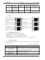
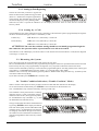
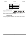
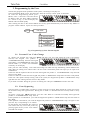
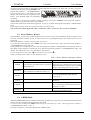
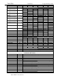
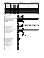
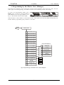
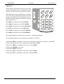
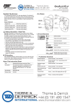
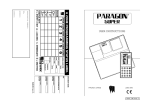
TeleT
ek
eleTek
CA60 Plus
Software Version 3.1
User Manual
May 2000
TeleTek
CA60Plus
User Manual
CONTENTS
1. CA60Plus Keypad ..................................................................................................................... 3
1.1. LED display ......................................................................................................................... 3
1.2. Keys ....................................................................................................................................... 4
1.3. Combinations of Keys ......................................................................................................... 4
1.4. Audible Indication ............................................................................................................... 4
2. Operating Modes ...................................................................................................................... 5
2.1. Day Mode (Disarmed) ......................................................................................................... 5
2.2. Security Mode (Armed) ....................................................................................................... 5
2.2.1. Full Security Mode ......................................................................................................... 5
2.2.2. Partial Security Mode ..................................................................................................... 5
2.2.3. Arming by Zone Bypassing ............................................................................................ 6
2.2.4. Arming by a Code ........................................................................................................... 6
2.3. Disarming the System .......................................................................................................... 6
2.4. Trouble Condition Indication (“Trouble Condition” Mode) ........................................... 6
2.5. Event Memory Erasure ....................................................................................................... 7
2.6. Silencing the Alarm ............................................................................................................. 7
3. Programming by the User ........................................................................................................ 8
3.1. Personal User Code Change ............................................................................................... 8
3.2. Zone Bypassing .................................................................................................................... 8
3.3. Event Memory Review ........................................................................................................ 9
3.4. CHIME Mode ...................................................................................................................... 9
4. Programming by the Master User (Manager) ..................................................................... 11
4.1. Master Code Change ......................................................................................................... 12
4.2. User Code Change ............................................................................................................. 12
4.3. User Code Rights Enablement.......................................................................................... 12
4.4. Zone Bypassing .................................................................................................................. 13
4.5. Event Memory Review ...................................................................................................... 13
4.6. CHIME Mode .................................................................................................................... 13
4.7. User Codes Access ............................................................................................................. 14
5. Vocabulary............................................................................................................................... 15
Appendix A .................................................................................................................................. 16
PROGRAMMING FORM ......................................................................................................... 17
2
TeleTek
CA60Plus
User Manual
1. CA60Plus Keypad
The CA60Plus security control panel keypad
is shown on Fig.1. The keypad provides the
system management. It is divided into a LED
display and a key panel.
1.1. LED display
The LED display is shown on Fig. 2. It is divided in three main groups:
• The first group contains the LEDs
READY, ARMED, TROUBLE and
BYPASS. It indicates the security control panel condition.
• The second group contains the LEDs
1, 2, 3, 4, 5 and 6 . It indicates the
security system detectors condition,
alarm event memory presence, additional information about the Trouble
Mode and the Programming Mode.
• The third group contains the LEDs
TAMPER and MEMORY. It indicates
alarm event memory presence.
1
2
3
4
5
6
7
8
9
ON
PROG
CLEAR
0
ENTER
Fig. 1 СА60Plus Keypad
Flashing LED
Not illuminating LED
Illuminating LED
Fig. 2 CA60Plus keypad LED display
The indications of the LEDs are discribed in Table 1. The light indications in the Event Memory Review are described
in Table 4, p. 9.
Table 1 CA60Plus Keypad LED Display Indication
LED
READY
ARMED
DOES NOT
LIGHT
• Αctivated
detector in the
armed area
• The area is
armed
The area is not
armed by the
security system
TROUBLE
No Trouble
BYPASS
No bypassed
zones
No activated
detector
LED 1, 2, 3, 4, 5
and 6
FLASHES
SLOWLY
At least one
Trouble
The zone is
bypassed
3
FLASHES
RAPIDLY
ILLUMINATES
CONSTANTLY
Programming
Mode
The alarm system is
ready to arm the area
• Programming
Mode
The alarm system is
armed
• Until the exit
time is expired
Programming
Mode
Programming
Mode
Activated
detector
Bypassed zones
• In case of Event
Memory
• In case of an indication
under Programming Mode
TeleTek
CA60Plus
User Manual
Table 1 CA60Plus Keypad LED Display Indication (continued)
LED
DOES NOT
LIGHT
FLASHES
SLOWLY
TAMPER
The security
system Tamper is
not activated
MEMORY
No Alarm Event
FLASHES
RAPIDLY
Continuous
damage in the
security system
Tamper
ILLUMINATES
CONSTANTLY
Tamper damage memory
Fire detector
activated
Alarm Event memory
1.2. Keys
The CA60Plus keypad contains the following 16 keys:
From 0 to 9 key are used
for entering the code and
for managing the control
panel
The PROG key followed by
a valid code is used for
activating a programming
mode
The ENTER key is used for
activating the Technical
Trouble mode and for
confirmation of entered data
1
2
5
4
ON key is used for
3
6
7
8
9
ON
PROG
CLEAR
1
2
3
4
5
6
7
8
9
ON
PROG
CLEAR
1
2
3
4
5
6
7
8
9
ON
PROG
CLEAR
0
arming the system
1
2
3
4
5
6
7
8
9
ON
PROG
CLEAR
0
ENTER
ENTER
CLEAR key is used
0
when necessary to cancel
the operator’s activity
ENTER
! and " keys are used in
0
case of an event memory
review
ENTER
1
2
3
4
5
6
7
8
9
ON
PROG
CLEAR
1
2
3
4
5
6
7
8
9
ON
PROG
CLEAR
0
ENTER
0
ENTER
1.3. Combinations of Keys
The CA60Plus keypad allows the following key combinations:
•
•
•
•
ON followed by 0 – the system enters the Full Security Mode
ON followed by 1 – the system enters the Partial Security Mode 1
ON followed by 2 - the system enters the Partial Security Mode 2
ON and ENTER – pressed together and kept for 2 seconds - the system enters the PANIC Mode
1.4. Audible Indication
The CA60Plus keypad has an internal buzzer, which provides additional audible indication. The signals and their
description are listed in Table 2.
Table 2 CA60Plus Audible Indication
AUDIBLE SIGNAL
Short audible signal
Two short audible signals
(ATTENTION beep)
Two continuous audible signals
(CONFIRMATION beep)
One continuous audible signal
(REJECTION beep)
DESCRIPTION
Pressed key on the keypad
Trouble or system Tamper damage. This audible signal could be silenced
before the damage restoring by a valid user code.
Confirms an operation on the keypad
Rejects an operation on the keypad
4
TeleTek
CA60Plus
User Manual
2. Operating Modes
2.1. Day Mode (Disarmed)
This mode allows free movement in the secured area. The security system detectors continue working without
causing an alarm.
If there are no activated detectors in the secured
area the READY LED will illuminate constantly.
If there are activated detectors in the secured
area the READY LED will not light and the
LEDs of the activated zones will flash.
2.2. Security Mode (Armed)
This mode arms the area. The system may enter Security Mode only when there are no activated zones, no alarm event
in process and at least one non-bypassed alarm zone is present. When the area is ready to enter the Security Mode the
LED READY will light.
When the command for entering the Secutity Mode is given, the exit time will begin.
Have in mind the duration of the exit time programmed by the engineer. When it is expired the alarm will be activated.
Follow strictly the exit route programmed by the engineer. Every step aside could cause an alarm activation.
2.2.1. Full Security Mode
This mode arms all the zones in the area.
When the area is ready to be armed press ON
followed by 0. The keypad will produce a beeping sound thus indicating that the exit time is running. All the zones - except these securing the exit
route - will be armed.
To silence the beeping sound from the keypad
press any key. When the exit time is expired the
whole area will be armed. The condition will be
indicated by the LED ARMED illuminating constantly.
2.2.2. Partial Security Mode
The CA60Plus security control panel allows partitioning of the zones into PART1 and PART2. These two parts are
programmed by the engineer. When PART1 or PART 2 is armed only the zones included in the respective part will be
in Security Mode.
When the system is ready to be armed press ON
followed by 1 to secure PART1 or ON followed
by 2 to secure PART2. On the display the LEDs
READY, ARMED and BYPASS will illuminate
constantly. The LEDs of the nonsecured zones will
flash slowly.
If the chosen part includes an entry/exit area an exit time will begin. To silence the audible signal from the
keypad press any key.
5
TeleTek
CA60Plus
User Manual
2.2.3. Arming by Zone Bypassing
Choose the zones that you desire to bypass and
follow the Full Security Mode arming procedure
(See 2.2.1). All the zones except the bypassed ones
will be armed. The disarmed zones will be indicated on the display by slowly flashing LEDs.
When the exit time is expired the indication on the display will be the same as if the area has entered Full
Security Mode.
2.2.4. Arming by a Code
The CA60Plus security panel could arm an area by confirming a code. When this option is programmed by the engineer
the above mentioned arming procedure is confirmed by a code:
Full Security
ON 0 (See 2.2.1) followed by a valid code
Partial Security
ON 1 (See 2.2.2) followed by a valid code
ON 2 (See 2.2.2) followed by a valid code
ATTENTION! The code that confirms arming should have an initially programmed right for
that. Otherwise the operation will be rejected and the area will not be armed.
The indication on the LED display will be the same as if the area has been armed without a code (See the diagrams
concerning 2.2.1 and 2.2.2).
2.3. Disarming the System
Every entrering an I/O part of the armed area will activate an entry time.
Have in mind the duration of the entry time programmed by the engineer. When it is expired the alarm will be activated.
Follow strictly the entry route programmed by the engineer. Every step aside could cause an alarm activation.
The area will be disarmed by entering a valid code with a programmed right for switching off the system. The keypad
will produce a “CONFIRMATION” beep (See Table 2, p. 4) and will return to Day Mode.
When the code is incorrectly entered the keypad will produce a “REJECTION” beep (See Table 2, p. 4) and the system
will remain under Security Mode.
If you make a mistake press CLEAR and re-enter the code.
2.4. Trouble Condition Indication (“Trouble Condition” Mode)
Table 3 contains a description of all the possible technical troubles and their indication on the display.
To exit the Technical Trouble Mode press CLEAR or wait one minute for the automatic exit.
The “ATTENTION” beep could be silenced by entering a valid code.
The CA60Plus control panel monitors constantly
important security system components. When a
technical trouble occurs, the keypad will produce
an “ATTENTION” beep (SeeTable 2, p. 4) and
the TROUBLE LED will flash slowly.
The type of the technical trouble could be detected
by pressing ENTER. On the display the READY
LED will flash rapidly and the TROUBLE LED
will flash slowly. An illuminating LED from the
second group will indicate the type of the technical trouble. For more information consult the keypad card with guidelines and if necessary call the
engineer.
6
TeleTek
CA60Plus
User Manual
Table 3 Technical Trouble Indication
LIGHTING LED
1
2
3
4
5
6
TECHNICAL TROUBLE
Blown fuse F3
Blown fuse F2
Low battery
No power supply 220 V
No telephone line
Unsuccessful communication
2.5. Event Memory Erasure
If a detector is activated when the system is armed
the keypad display will indicate the zone and what
kind of alarm event has occurred (See Table 1, p.
3).
When the system is disarmed this information will remain on the display. When the cause for the alarm event is defined
the memory on the display could be erased by entering a valid code.
The alarm events indicated by the illuminating TAMPER LED could be erased only by the Master Code.
2.6. Silencing the Alarm
In case of an activating of the security system alarm enter a valid user code to silence the alarm signal. Consult the
keypad display for the possible cause.
7
TeleTek
CA60Plus
User Manual
3. Programming by the User
The user may program certain parameters of the system, concerning its everyday use.
The Programming Mode can be activated only when the security control panel is disarmed.
To enter the Programming Mode press
PROG, enter a valid user code and choose
an address (The one digit address numbers
are shown on Fig. 3). On the display the
READY LED will flash rapidly.
After entering the data in the chosen address the security panel automatically will return to Day Mode. To
program another address repeat the same procedure.
PROG
User Code
0
New User Code
1
Zone Bypassing
2
3
Event Memory
Review
Enabled/Disabled
CHIME mode
1
2
3
4
5
6
Zone 1
Zone 2
Zone 3
Zone 4
Zone 5
Zone 6
Fig. 3 Programming by User. General diagram
3.1. Personal User Code Change
To change your personal user code press PROG and enter your user code. When the code is successfully
entered, the keypad will produce a
“CONFIRMATION”beep. Press 0. The keypad
will produce a “CONFIRMATION” beep again
and the LEDs 3, 4, 5 and 6 will illuminate
constantly on the display.
Enter your new code carefully. After each entered digit one LED will stop illuminating, which indicates how
many digits are waiting to be entered. After the new code is entered the panel will expect you to repeat it for
confirmation.
If the first and the repeated code are the same the keypad will produce a “CONFIRMATION” beep and will
return to Day Mode.
If the two codes are not the same the keypad will produce a “REJECTION” beep and will return to Day Mode.
If the new code repeats already existing code in the system, the keypad will produce a “REJECTION” beep
right after the first entering and will return to Day Mode.
If you make a mistake during the process of entering the code press CLEAR and reenter the code.
3.2. Zone Bypassing
Zone bypassing is needed when a trouble in certain zone has occurred. When armed the system will secure
all the zones except the bypassed ones. Having this in mind it is desirable that this security mode is rarely
used.
To bypass a zone press PROG and enter your user code. When it is entered successfully the keypad will
produce a “CONFIRMATION” beep. Press 1.
If this operation is not allowed for your code the keypad will produce a “REJECTION” beep and will return to
Day Mode.
If the operation is allowed for your code the keypad will produce a “CONFIRMATION” beep. To bypass a zone
press the key corresponding to its number.
On the display will illuminate the respective
zone LED. You may cancel the process by
pressing again the key of the zone number.
The LED will not light.
8
TeleTek
CA60Plus
User Manual
At the end of the procedure on the display should illuminate the LEDs of the zones that you desire to bypass.
Confirm your choice by pressing ENTER. The
keypad will produce a “CONFIRMATION”
beep and will return to Day Mode. On the
display will flash slowly the bypassed zones
LEDs. The BYPASS LED will illuminate
constantly.
If you choose to cancel the procedure without bypassing zones press CLEAR. The keypad will produce a
“REJECTION” beep and will return to Day Mode.
The 24 hour armed zones could not be bypassed. If you try to do that the keypad will produce a “REJECTION”
beep.
If you bypass all the zones the system will refuse to arm the area.
The zones will remain bypassed until a valid user code is entered or the system is disarmed.
3.3. Event Memory Review
The ÑÀ60Plus security control panel memorizes 255 events. It stores the information about the alarm events
from the “Technical Trouble” group, as well as about every arming/disarming of the system and every zone
bypassing.
The Event Memory could be reviewed, but not erased.
To review the Event Memory press PROG and enter your personal user code. The keypad will produce a
“CONFIRMATION” beep. Press 2.
If this operation is not allowed for your code the keypad will produce a “REJECTION” beep and will return to
Day Mode. If this operation is allowed for your code the keypad will produce a “CONFIRMATION” beep. The
display will indicate the last event registered in the memory.
To see the previous event press " . To see the next event press ! .
Table 4 contains a description of the registered events.
Table 4 Event Memory Massages Coding
LED
ARMED
TROUBLE
BYPASS
FLASHES
ILLUMINATES
Disarming the area. A LED from the second
group indicates the number of the user who has Arming the area. A LED from the second group
indicates the number of the user who has armed
disarmed the area.
the area - if the arming was done by a code.
Technical Trouble. A LED from the second
group specifies the trouble (See Table 3, p.7).
There are bypassed zones. They are indicated
by constantly illuminating LEDs from the
second group.
Detector Bypassing OR additional to the other
indications
TROUBLE in the TAMPER circuit. A LED from
TAMPER
the second group specifies the zone where the
trouble has occurred
An alarm event has occurred. A LED from the
MEMORY
second group specifies the zone.
The "test message by the communicator" event is indicated by all the LEDs flashing rapidly.
LEDs 1, 2, 3, 4,
5 and 6
3.4. CHIME Mode
When the CHIME mode signal is enabled, the activating of a detector in every zone, for which this parameter has been
chosen, will cause a ringing sound produced by the keypad.
To activate this mode press PROG and enter your personal user code. The keypad will produce a
“CONFIRMATION” beep. Press 3.
Pressing any digit key will enable/disable the CHIME mode.
9
TeleTek
CA60Plus
User Manual
When the CHIME mode is disabled the LEDs
from 1 to 6 will not light.
When the CHIME mode is enabled, the LEDs
from 1 to 6 will illuminate constantly.
To confirm your choice press ENTER. The keypad will produce a “CONFIRMATION” beep and will return to
Day Mode.
To cancel your choice press CLEAR. The keypad will produce a “REJECTION” beep and will return to Day
Mode.
10
TeleTek
CA60Plus
Just for the record
JUST FOR THE RECORD
Customer
Address
Contacts
Phone
Phone
Phone
Phone
1.
2.
3.
Code
Note
Installer's Code
Installation Date
Programming Work Sheet
10 Zone Balance
ALARM
DUAL
DOUBLE
PART1
PART2
CHIME
FAST
Note
AC LOSS
BAT LOW
FUSE
POL +/-
FOLLOW
MEDICAL
FIRE
TAMPER
PANIC
Attributes
PS/BYPASS
11
12
13
14
15
16
ALARM
Zone
Entry/Exit
Zone Type
Note
Zone 1
Zone 2
Zone 3
Zone 4
Zone 5
Zone 6
21
22
23
24
MEDICAL
ON/OFF
FIRE/RST
FIRE
TAMPER
PANIC
Programmable
Outputs
ALARM
Attributes
PGM 1
PGM 2
PGM 3
SIREN
30 Exit Time
31 Entry Time
32 Bell Time
33 Delay Time
40 Arming by Code
sec
sec
min
min
No
Yes
TeleTek
CA60Plus
Programming table
PROGRAM MENU
ADDRESS
LED 1
LED 2
LED 3
LED 4
LED 5
LED 6
LOOP TYPE
10
DUAL - LED1 to LED6 do not light
ALARM - LED1 to LED6 light
ZONE 1
11 ! Entry/Exit ALARM
PANIC
TAMPER
FIRE
MEDICAL
ATTRIBUTES ZONE 1
" FOLLOW DOUBLE
PART1
PART2
CHIME
FAST
ZONE 2
12 ! Entry/Exit ALARM
PANIC
TAMPER
FIRE
MEDICAL
ATTRIBUTES ZONE 2
" FOLLOW DOUBLE
PART1
PART2
CHIME
FAST
ZONE 3
13 ! Entry/Exit ALARM
PANIC
TAMPER
FIRE
MEDICAL
ATTRIBUTES ZONE 3
" FOLLOW DOUBLE
PART1
PART2
CHIME
FAST
ZONE 4
14 ! Entry/Exit ALARM
PANIC
TAMPER
FIRE
MEDICAL
ATTRIBUTES ZONE 4
" FOLLOW DOUBLE
PART1
PART2
CHIME
FAST
ZONE 5
15 ! Entry/Exit ALARM
PANIC
TAMPER
FIRE
MEDICAL
ATTRIBUTES ZONE 5
" FOLLOW DOUBLE
PART1
PART2
CHIME
FAST
ZONE 6
16 ! Entry/Exit ALARM
PANIC
TAMPER
FIRE
MEDICAL
ATTRIBUTES ZONE 6
" FOLLOW DOUBLE
PART1
PART2
CHIME
FAST
PGM 1
21 ! ALARM
PANIC
TAMPER
FIRE
FIRE/RST ON/OFF
" MEDICAL PS/bypass AC LOSS BAT LOW
FUSE
Pol+ / PGM 2
22 ! ALARM
PANIC
TAMPER
FIRE
FIRE/RST ON/OFF
" MEDICAL PS/bypass AC LOSS BAT LOW
FUSE
Pol+ / PGM 3
23 ! ALARM
PANIC
TAMPER
FIRE
FIRE/RST ON/OFF
" MEDICAL PS/bypass AC LOSS BAT LOW
FUSE
Pol+ / SIREN OUTPUT
24
ALARM
PANIC
TAMPER FIRE/ALW
EXIT TIME
30
0-9 SEC 10-19 SEC 20-29 SEC 30-39 SEC 40-49 SEC 50 - 59 SEC
ENTRY TIME
31
0-9 SEC 10-19 SEC 20-29 SEC 30-39 SEC 40-49 SEC 50 - 59 SEC
BELL TIME
32
1 MIN
2 MIN
3 MIN
4 MIN
5 MIN
6 MIN
BELL DELAY
33
1 MIN
2 MIN
3 MIN
4 MIN
5 MIN
6 MIN
SET WITH CODE
40
NO - LED1 to LED6 do not light
YES - LED1 to LED6 light
USER CODE 1
41
UNSET
FULSET PARTSET1 PARTSET2
LOG
BYPASS
USER CODE 2
42
UNSET
FULSET PARTSET1 PARTSET2
LOG
BYPASS
USER CODE 3
43
UNSET
FULSET PARTSET1 PARTSET2
LOG
BYPASS
USER CODE 4
44
UNSET
FULSET PARTSET1 PARTSET2
LOG
BYPASS
USER CODE 5
45
UNSET
FULSET PARTSET1 PARTSET2
LOG
BYPASS
USER CODE 6
46
UNSET
FULSET PARTSET1 PARTSET2
LOG
BYPASS
MANGER ACCESS
47
NO - LED1 to LED6 do not light
YES - LED1 to LED6 light
ENGINEER CODE
50
DIGIT 1
DIGIT 2
DIGIT 3
DIGIT 4
RESET ENABLE
51
NO - LED1 to LED6 do not light
YES - LED1 to LED6 light
DEFAULT SETTINGS
52
Press the keys from 1 to 6 consequently and confirm by ENTER
PART. RESET
53
Press the keys from 1 to 6 consequently and confirm by ENTER
54 to 89 address indication, concerning the communicator parameters, is hexadecimal, the LEDs 3,4,5,6 are
used (Lower BIT - LED 6)
54
Max phone number lenght 16 symbols, pause=ON+2, DTMF =ON+1
TEL No PC FOR UDL
55
4 digits. Default 1234
PC ID FOR UDL
56
4 digits. Default 1234
PANEL ID FOR UDL
57
CALL BACK
NO - LED1 to LED6 do not light
YES - LED1 to LED6 light
58
1 digit. (0 to 9)
No OF RINGS
59
ANSW. MACHINE
NO - LED1 to LED6 do not light
YES - LED1 to LED6 light
TEL No 1
60
Max phone number lenght 16 symbols, pause=ON+2, DTMF =ON+1
PANEL ID 1
61
3 or 4 digits (depending on the report 3х or 4х)
REPORT 1
62
The report number included in the applied table is entered
х1/х2
63
x2 - LED1 to LED6 do not light
x1 - LED1 to LED6 light
TEL No 2
64
Max phone number lenght 16 symbols, pause=ON+2, DTMF =ON+1
PANEL ID 2
65
3 or 4 digits (depending on the report 3х or 4х)
REPORT 2
66
The report number included in the applied table is entered
х1/х2
67
x2 - LED1 to LED6 do not light
x1 - LED1 to LED6 light
WAIT DIAL TONE
68
NO - LED1 to LED6 do not light
YES - LED1 to LED6 light
RESET Parameters
TeleTek
CA60Plus
PROGRAM MENU
CLOCK
TEST TIME
TEST PERIOD
TEST CODE
LF DELAY
ALARM CODE
PANIC CODE
TAMPER CODE
FIRE CODE
MEDICAL CODE
BYPASS CODE
ON CODE
OFF CODE
TROUBLE CODE
RESTORE CODE
WALK TEST
LED TEST
OUTPUTS TEST
COMMUNIC.DISPLAY
DISPLAY LOG
ADDRESS
70
71
72
73
74
80
81
82
83
84
85
86
87
88
89
90
91
92
93
94
Up/Down Load Display
95
Value
0
1
2
3
4
5
6
7
8
9
A
B
C
D
E
F
LED 3
Ο
Ο
Ο
Ο
Ο
Ο
Ο
Ο
⊗
⊗
⊗
⊗
⊗
⊗
⊗
⊗
Programming table
LED 1
LED 2
LED 3
LED 4
Clock Settings ( HH:MM)
Test peport time ( HH:MM)
Auto reporting(DD)
TEST code. RESET A value.
LF delay indication (ММ)
ALARM Report code. RESET Value 1.
PANIC Report code. RESET Value 2.
TAMPER Report code. RESET Value 3.
FIRE Report code. RESET Value 4.
MEDICAL Report code. RESET Value 5.
BYPASS Report code. RESET Value 6.
ON Report code. RESET Value 7.
OFF Report code. RESET Value 8.
TROUBLE Report code. RESET Value 9.
RESTORE Report code. RESET Value B.
ZONE 1
ZONE 2
ZONE 3
ZONE 4
PGM1
PGM2
PGM3
Dial Tone Dialing
Wait HS
LOG File Review
Ring
LEDs Status
LED 4 LED 5
Ο
Ο
Ο
Ο
Ο
⊗
Ο
⊗
⊗
Ο
⊗
Ο
⊗
⊗
⊗
⊗
Ο
Ο
Ο
Ο
Ο
⊗
Ο
⊗
⊗
Ο
⊗
Ο
⊗
⊗
⊗
⊗
Dialing
LED 6
Ο
⊗
Ο
⊗
Ο
⊗
Ο
⊗
Ο
⊗
Ο
⊗
Ο
⊗
Ο
⊗
Wait
Carrier
Key
combination
0
1
2
3
4
5
6
7
8
9
ON and 0
ON and 1
ON and 2
ON and 3
ON and 4
ON and 5
LED 5
LED 6
ZONE 5
ZONE 6
SIREN
Send Data Wait Koff
Send Data
All Sent
Receive
Data
Legend: ⊗ - light O - does not
light
The combination “ON and 1”
means pressing the ON key
followed by the 1 key.
RESET CODES:
Master Code
User Code 1
User Code 2
User Code 3
-
0000
1111
2222 - no rights
3333 - no rights
User Code 4
User Code 5
User Code 6
Engineer Code
-
4444 - no rights
5555 - no rights
6666 - no rights
7777
TeleTek
CA60Plus
Just for the record
41
42
43
44
45
46
BYPASS
LOG
PARTSET 2
PARTSET 1
FULSET
User Codes
UNSET
User Code Rights
Note
USER CODE 1
USER CODE 2
USER CODE 3
USER CODE 4
USER CODE 5
USER CODE 6
47 Manager access to
User Code Rights
No
Yes
No
Yes
No
Yes
No
Yes
х2
х1
67 Report Format 2
х2
х1
68 Wait Dial Tone
No
Yes
50 Engineer Code
51 RESET Enable
54 PC Phone Number for Up/Down Load
55 PC ID for Up/Down Load
56 Panel ID for Up/Down Load
57 Call Back
58 Number of Rings for Up/Down Load
59 Answering Machine Override Delay
60 Primary Phone Number (Phone1)
61 Subscriber Account No 1
62 Communication Report 1
63 Report Format 1
64 Secondary Phone Number (Phone2)
65 Subscriber Account No 2
66 Communication Report 2
71 Test Report Time
hour
72 Auto reporting
days
73 Test Report Code
74 Line Fault Indication Delay
80 ALARM Report Code
81 PANIC Report Code
82 TAMPER Report Code
83 FIRE Report Code
84 MEDICAL Report Code
85 BYPASS Report Code
86 ARM Report Code
87 DISARM Report Code
88 TROUBLE Report Code
89 RESTORE Report Code
minutes
minutes
TeleTek
CA60Plus
User Manual
4. Programming by the Master User (Manager)
The master user (manager) of the system may program certain parameters such as the user codes, the user
codes rights, the zone bypassing, the buffer of events review and the personal code change.
To enter the Programming Mode press
PROG, enter the master code and address
(The addresses are two digit numbers as in
Fig. 4). The READY LED will flash rapidly.
When the data in certain address is entered the security control panel will enter Day Mode automatically. For
another address programming the procedure is the same.
PROG
Master Code
00 New Master Code
01 New User Code 1
02 New User Code 2
03 New User Code 3
04 New User Code 4
05 New User Code 5
User Code Rights X
06 New User Code 6
11 User Code Rights 1
1
Disarming
12 User Code Rights 2
2
Arming
3
Arming PART 1
4
Arming PART 2
13 User Code Rights 3
14 User Code Rights 4
5
15 User Code Rights 5
6
Event Memory
Review
Zone Bypassing
16 User Code Rights 6
10
20
30
Zone Bypassing
Event Memory
Review
Enabled/Disabled
CHIME mode
1
2
3
4
5
6
Zone 1
Zone 2
Zone 3
Zone 4
Zone 5
Zone 6
40 User Codes Access
Fig. 4 Programming by The Master User. General Diagram
11
TeleTek
CA60Plus
User Manual
4.1. Master Code Change
To change the master code press PROG and enter
the master code. When the code is successfully
entered the keypad will produce a
“CONFIRMATION” beep. Press 0 twice. The
keypad will produce the same audible signal.
Enter your new code carefully. After each entered digit one LED will stop illuminating, which indicates how
many digits are waiting to be entered. After the new code is entered the panel will expect you to repeat it for
confirmation.
If the first and the repeated code are the same the keypad will produce a “CONFIRMATION” beep and will
return to Day Mode.
If the two codes are not the same the keypad will produce a “REJECTION” beep and will return to Day Mode.
If the new code repeats already existing code in the system the keypad will produce a “REJECTION” beep
right after the first entering and will return to Day Mode.
If you make a mistake during the process of entering the code press CLEAR and reenter the code.
4.2. User Code Change
To change a user code press PROG and
enter the master code. When the code is
successfully entered the keypad will produce
a “CONFIRMATION” beep. Enter the address
of the desired user code (See Fig. 4). The
keypad will produce the same audible signal.
Enter your new code carefully . After each entered digit one LED will stop illuminating, which indicates how
many digits are waiting to be entered. After the new code is entered the panel will expect you to repeat it for
confirmation.
If the first and the repeated code are the same the keypad will produce a “CONFIRMATION” beep and will
return to Day Mode.
If the two codes are not the same the keypad will produce a “REJECTION” beep and will return to Day Mode.
If the new code repeats already existing code in the system the keypad will produce a “REJECTION” beep
right after the first entering and will return to Day Mode.
If you make a mistake press CLEAR and reenter the code.
4.3. User Code Rights Enablement
This procedure is possible only in case the engineer has given the manager the respective right.
It enables with rights to every user code separately. It is possible that a certain code is not given any right or
given any combination of rights. Table 5 describes every user code right options.
If a code is not enabled with rights it becomes non-active (See Fig. 4).
To enable an user code with rights press
PROG and enter the master code. If the code
is successfully entered the keypad will
produce a “CONFIRMATION” beep. Enter an
address having in mind Fig. 4. If the manager
is not enabled with an access right the keypad will produce a “REJECTION” beep and will return to Day
Mode. If the manager is enabled with an access right the keypad will produce a “CONFIRMATION” beep.
Table 5 User code rights
USER CODE RIGHT
UNSET
FULLSET
PARTSET1
PARTSET2
LOG reviewing
BYPASS
DESCRIPTION
Enables the respective user code to disarm the area
Enables the full arming of the area when an user code confirmation is
obligatory
Enables the arming of PART 1 when an user code confirmation is
obligatory
Enables the arming of PART 2 when an user code confirmation is
obligatory
Enables the respective user code to review the event memory
Enables the respective user code to bypass zones
12
TeleTek
CA60Plus
User Manual
Having in mind Fig. 4 and Table 5 use the keys from 1 to 6 to enable the desired rights. Every next pressing
of the respective key will change alternatively the condition of the enabled right - active or non-active.
At the end of procedure on the display should light only the LEDs of the desired rights.
When you are sure that you have entered the data successfully confirm your choice by pressing ENTER. The
keypad will produce a “CONFIRMATION” beep and will return to Day Mode.
If you choose to cancel the address changing procedure press CLEAR. The keypad will produce a
“REJECTION” beep and will return to Day Mode.
4.4. Zone Bypassing
Zone bypassing is needed when a trouble in a certain zone has occurred. When armed the system will
secure all the zones except the bypassed ones. Having this in mind it is desirable that this security mode is
rarely used.
To bypass certain zones press PROG and
enter the master code. When it is entered
successfully the keypad will produce a
“CONFIRMATION” beep. Press 1 and 0. The
keypad will produce a “CONFIRMATION”
beep again.
Bypass the zones by pressing the digit key corresponding to the zone number. On the display will light the
LED of the respective zone. By next pressing of the key the zone LED will stop lighting. At the end of the
procedure on the display will remain the LEDs of the zones that are to be bypassed.
The keypad will produce a “CONFIRMATION” beep and will return to Day Mode. On the display the LEDs of
the bypassed zones will flash slowly. The BYPASS LED will illuminate constantly.
Confirm your choice by pressing ENTER. The
keypad will produce a “CONFIRMATION”
beep and will return to Day Mode. On the
display the LEDs of the bypassed zones will
flash slowly. The BYPASS LED will
illuminate.
If you choose to cancel the procedure without bypassing zones press CLEAR. The keypad will produce a
“REJECTION” beep and will return to Day Mode.
The 24 hour armed zones could not be bypassed. If you try to do that the keypad will produce a “REJECTION”
beep
If you bypass all the zones the system will refuse to arm the area.
The zones will remain bypassed until a valid user code is entered or the system is disarmed.
4.5. Event Memory Review
It stores the information about the alarm events from the “Technical Trouble” group, as well as about every
arming/disarming of the system and every zone bypassing.
The Event Memory could be reviewed, but not erased.
To review the Event Memory press PROG and enter Master Code. The keypad will produce a
“CONFIRMATION” beep.
Press 2 and 0.
The keypad will produce a “CONFIRMATION” beep. The display will indicate the last event registered in the
memory.
To see the previous event press " . To see the next event press ! .
Table 4 describes the meaning of the registered events.
4.6. CHIME Mode
When the CHIME mode signal is enabled the activating of a detector in every zone, for which this parameter has been
chosen, will cause a ringing sound produced by the keypad.
To activate this mode press PROG and enter the master code. The keypad will produce a “CONFIRMATION”
beep. Press 3 and 0.
Pressing any digit key will enable/disable the CHIME mode.
13
TeleTek
CA60Plus
User Manual
When the CHIME mode is disabled the LEDs
from 1 to 6 will not light.
When the CHIME mode is enabled, the LEDs
from 1 to 6 will illuminate constantly.
To confirm your choice press ENTER. The keypad will produce a “CONFIRMATION” beep and will return to
Day Mode.
To cancel your choice press CLEAR. The keypad will produce a “REJECTION” beep and will return to Day
Mode.
4.7. User Codes Access
When the USER CODES ACCESS is enabled the user and master codes are visible via Up/Down Load software.
To configure USER CODES ACCESS press PROG and enter the master code. The keypad will produce a
“CONFIRMATION” beep. Press 4 and 0.
Pressing any digit key will enable/disable the USER CODES ACCESS.
When the USER CODES ACCESS is
enabled the LEDs from 1 to 6 will not light.
When the USER CODES ACCESS is
disabled, the LEDs from 1 to 6 will illuminate
constantly.
To confirm your choice press ENTER. The keypad will produce a “CONFIRMATION” beep and will return to
Day Mode.
To cancel your choice press CLEAR. The keypad will produce a “REJECTION” beep and will return to Day
Mode.
14
TeleTek
CA60Plus
User Manual
5. Vocabulary
PANIC
PART 1 , PART2
Alarm
Alarm Event
TAMPER
Entry Route
Entry Time
Mas ter Us er
(MANAGER)
READY
Day Mode
(DIS ARMED)
B YPAS S
Zone
Exit Route
Exit time
Engineer
CHIME Mode
Code
Rejaction
Event Memory
Arming
Confirmation
Us er
Code rig hts
S ecurity Mode
(ARMED)
Dis arming
Event
A larm Sys tem co nd ition activated b y th e u s er in cas e of an attack.
In itially d etermined p arts o f th e s y s tem that may includ e from 1 up to 6 zo nes . Th ey are
u s ed fo r armin g a p art o f th e s ecu red area with ou t a n eces s ity o f b y p as s in g th e res t o f th e
zo n es .
A ctiv atin g o f the s y s tem s iren
A n even t in the s ecu rity s ys tem th at cau s es a s iren activ atin g
A ll th e s y s tem compo n en ts ( d etecto rs , con tro l p anel, key ad and s iren) are mo n ito red
con s tan tly b y th e s y s tem. In cas e of an in terv en tio n in an y o f th em - reg ardles s th e
o p eratin g mo de - th e s iren is activ ated an d a vis ual in d icatio n occu rs o n the keyp ad.
Th e ro u te th at s h o u ld b e u s ed fo r area acces u n der Secu rity M od e.
Th e time n eed ed fo r d is armin g th e s ys tem b y en terin g a v alid cod e
A s tu ff memb er with th e n eces s ary kno wledg e an d abilities to manag e an d pro g ram th e
s ys tem
Th e s ecurity pan el co n ditio n th at allo ws th e s y s tem to b e armed
In this mod e th e s ecu rity p an el activates the alarm o n ly in cas e o f an attack, fire o r
TA M PER
A n o p eratio n wh ich b y p as s es o ne or s ev eral zon es . The n ext time th e s y s tem en ters the
Secu rity M o de, all th e zo n es excep t th e b yp as s ed on es will b e armed
A p art o f th e s ecu red p remis es wh ere th e d etectors are s itu ated
Th e ro u te th at s h o u ld b e u s ed fo r exitin g th e area u n d er Secu rity M o de.
Th e time n eed ed fo r leav ing th e area after th e s y s tem h as b een armed
A q u alified member of th e eng in eerin g co mp an y
A rin g in g au d ib le s ig n al fro m the keyp ad in Day M od e wh en certain d etectors in initially
d etermin ed zo nes h av e b een activ ated
A co mb in atio n of fo u r d ig its that s h o uld be en tered o n th e key pad fo r o peratin g with th e
s ecurity pan el
Cancelling an u s er activ ity b y p res s in g CLEAR or from the s ecurity panel. It is
accompan ied b y an au d ib le s ig n al
W h en an alarm ev ent h as occu rred in th e s y s tem the s ecu rity p anel will memorize its
p ro perties
A n activ ity th at ch ang es th e co n d itio n o f th e s y s tem fro m Day M o d e to Secu rity M o d e
Co n firmin g of an u s er activ ity b y pres s ing ENTER or from the s ecurity panel. It is
accompan ied b y an au d ib le s ig n al
A p ers o n who u s es th e s ecu rity p anel d aily
A lis t o f activ ities p erfo rmed b y the s y s tem after en terin g a co d e
Th e con tro l p anel is fu n ctio n in g an d th e s y s tem is armed
A n activ ity th at ch ang es th e co n d itio n o f th e s y s tem fro m Secu rity M o de to Day M o d e
Ev ery ch an g e in th e co nd ition o f th e s ecu rity p an el is called " even t" . i. e. activating o f a
d etecto r, techn ical tro u b le, Tamp er tro u ble, arming /d is armin g th e area, etc.
TROUB LE
Th e con tro l p anel mon ito rs co n s tan tly imp ortan t s ecu rity s ys tem co mp on ents . In cas e of a
tro u ble in an y o f th e co mp o n en ts , th e key pad d is p lay will p ro b ab ly s p ecify th e in fo rmatio n
Fals e Alarm
A ctiv atin g th e alarm o f th e s ecu tity p an el th at is n ot cau s ed by a real in terven tio n in th e
s ecured area or b y an attempt to caus e a d amag e in the s y s tem
RESET CODES:
Master Code
User Code 1
User Code 2
User Code 3
User Code 4
User Code 5
User Code 6
Engineer Code
-
0000
1111
2222 3333 4444 5555 6666 7777
no
no
no
no
no
rights
rights
rights
rights
rights
15
TeleTek
CA60Plus
User Manual
LED RDY corresponds to the LED READY
PR
O
G
M
EM
The LED indicators are divided into two columnsone for the service indications and the second one
for the zone indications. The indications are compatible by functions with these which are described
in the Instruction, as:
AR
M
The LED61 keypad fulfills all functions of the other
design LED keypad and it is compatible with all
software versions of the control panel CA60 plus.
DI
SA
RM
Appendix A
1
2
3
4
5
6
7
8
9
CLR
0
ENT
LED ARM corresponds to the LED ARMED
LED TRBL corresponds to the LED TROUBLE
LED BPS corresponds to the LED BYPASS
LED TAMP corresponds to the LED TAMPER
LED MEM corresponds to the LED MEMORY.
The keypad buttons are divided into two groups – functional and digital.
The functional buttons of two keypads are compatible as follows:
Push-button ARM is compatible to the push - button ON. All functions with push – button ON
from the old keypad have to be completed with push-button ARM.
Push-button PROG is compatible to the push - button PROG
Push-button DISARM is not used.
Push-button MEM is not used.
Push-button CLR is compatible to the push - button CLEAR.
Push-button ENT is compatible to the push - button ENTER.
16
TeleTek
CA60Plus
User Manual
PROGRAMMING FORM
(to be filled in by the installer)
10 Zone Balance
ALARM
DUAL
DOUBLE
PART1
PART2
CHIME
FAST
Note
AC LOSS
BAT LOW
FUSE
POL +/-
FOLLOW
MEDICAL
FIRE
TAMPER
PANIC
Attributes
PS/BYPASS
11
12
13
14
15
16
ALARM
Zone
Entry/Exit
Zone Type
Note
Zone 1
Zone 2
Zone 3
Zone 4
Zone 5
Zone 6
21
22
23
24
MEDICAL
ON/OFF
FIRE/RST
FIRE
TAMPER
PANIC
Programmable
Outputs
ALARM
Attributes
PGM 1
PGM 2
PGM 3
SIREN
30 Exit Time
31 Entry Time
32 Bell Time
33 Delay Time
sec
sec
min
min
40 Arming by Code
No
Yes
41
42
43
44
45
46
BYPASS
LOG
PARTSET 2
PARTSET 1
FULSET
User Codes
UNSET
User Code Rights
Note
USER CODE 1
USER CODE 2
USER CODE 3
USER CODE 4
USER CODE 5
USER CODE 6
47 Manager access to
User Code Rights
No
Yes
17
TeleTek
CA60Plus
User Manual
54 PC Phone Number for Up/Down Load
55 PC ID for Up/Down Load
56 Panel ID for Up/Down Load
57 Call Back
No
Yes
No
Yes
58 Number of Rings for Up/Down Load
59 Answering Machine Override Delay
60 Primary Phone Number (Phone1)
61 Subscriber Account No 1
62 Communication Report 1
63 Report Format 1
х2
х1
67 Report Format 2
х2
х1
68 Wait Dial Tone
No
Yes
64 Secondary Phone Number (Phone2)
65 Subscriber Account No 2
66 Communication Report 2
71 Test Report Time
hour
72 Auto reporting
days
73 Test Report Code
74 Line Fault Indication Delay
minutes
80 ALARM Report Code
81 PANIC Report Code
82 TAMPER Report Code
83 FIRE Report Code
84 MEDICAL Report Code
85 BYPASS Report Code
86 ARM Report Code
87 DISARM Report Code
88 TROUBLE Report Code
89 RESTORE Report Code
18
minutes
TeleTek
CA60Plus
NOTE:
19
User Manual
WARRANTY
Warranty conditions for the CA60 plus may vary from country to country. Please
consult your local dealer for complete waranty information. In all cases, the warranty does not cover malfunctions arising from installer error or failure to follow
installation/operation instructions, nor does it aplly to damages due to causes
beyond the control of TeleTek Ltd., such as lighting, excessive voltage, mechanical
shock or water damage.
LIABILITY
Under no circumstances shall TeleTek Ltd. be held liable for any direct or indirect
damages, loss of anticipated profits, loss of time or any other losses incurred by
the buyer in connection with the purchase, installation, operation or failure of this
product.
WARNING
This security system should undegro frequent testing. however, despite regular
testing, and due to, but not limited to, criminal tampering or electrical disruption, it
is possible for this product to fail to perform as expected.
Te le Tek ®
BASA
BulgarianAssociation
System Alarm
18020053
Distributed by: