1
USOO8424040B2
(12) United States Patent
(10) Patent 190.;
Klosterman
(54)
(75)
(45) Date of Patent:
4,706,121 A
11/1987 Young
TELEVISION SYSTEM
4,751,578 A
4,776,038 A
6/1988 Reiter et a1.
10/1988 Testin et al.
Inventor:
4,908,713 A
4,914,517 A
Brian Lee Klosterman, San Ramon, CA
(Us)
3/1990 LeVine
4/1990 Duf?eld
(Continued)
Fremont, CA (US)
Notice:
FOREIGN PATENT DOCUMENTS
Subject to any disclaimer, the term ofthis
DE
39 21847 A
1/1991
DE
41 17 239 C2
12/1992
patent is extended or adjusted under 35
C
U.S.C. 154(0) by 961 days.
Filed;
.
d
( Ommue )
(21) APPI- NO-I 11/841,521
(22)
Apr. 16, 2013
MULTI-SOURCE SWITCHING INA
(73) Assignee: Starsight Telecast, Incorporated,
(*)
US 8,424,040 B2
OTHER PUBLICATIONS
Aug, 20, 2007
Hofmann, J., “The Consumer Electronic Bus: An Integrated Multi
Media LAN for the Home,” International Journal of Di g ital and
(65)
Pl‘iOl‘ PllblicatIOIl Data
US 2008/0134243 A1
Analog Communication Systems, vol. 4, No. 2, 1991, pp. 77-86.
Jun. 5, 2008
(Continued)
Related US. Application Data
(63)
Continuation of application No. 10/441,475, ?led on
May 19, 2003, which is a continuation of application
Primary Examiner * pankaj Kumar
Assistant Examiner * Sahar Baig
No, 09/612,352, ?led on Jul. 6, 2000, now abandoned,
(74) Attorney] Agent] or Firm i Ropes & Gray LLP
continuation of application No. 08/423,410, ?led on
Apr. 17, 1995, now abandoned.
(57)
whlch 1s a contmuation of applicatlon No. 08/810,199,
?led on Mar. 3, 1997, now abandoned, which is a
Int- ClH04N 5/445
(52) U-s- Cl-
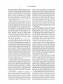
The present invention provides a tuning scheme for coordi
nating schedule information and programs received from
multiple sources (26, 28, 30 and 34). In the preferred embodi
ment, anidenti?er associatedwiththe program’s channel (52)
(51)
(58)
ABSTRACT
(2011-01)
UISPC ......... ...... ............ .. 725/48; 725/39; 725/51
Field of Classi?cation Search .................. .. 725/39,
_
_
_ 725/48’ 51
is used to identify a source device (26’ 28’ 30 or 34)' When a
user selects a program (60 or 62)1istedin displayed schedule
See apphcanon ?le for Complete SearCh hlswry'
attached to the program’s channel (52). The system (10) then
,
(56)
information (50), the system (10) reads the source identi?er
carries out an automatic switching/tuning such that the
References Clted
required source device (26, 28, 30 or 34) is input to the
Us PATENT DOCUMENTS
delstina(t1ion device (212), apd a tuner is then tuned to the
3,730,986 A
3,745,240 A
4,488,179 A
4,598,423 A
5/1973 Morchand
7/1973 Morchand et al.
se me program 5 C anne (52)
12/1984 Kruger et al.
7/ 1986 Hettiger
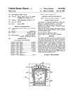
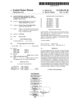
26 Claims, 4 Drawing Sheets
OTHER
'°\
INPUTS
» 30
ID \
{/
#8
54
[26
CABLE
V '71
CABLE aux
TELEVISION
(ix-£1928
"w M
T‘
\I\
29\
W "‘2
W _‘
"w
’2‘
J22
{:4 20 r“ TELEVISION
0000000000
sex
45
94/
24
\/
f
VCR
b,
40
,
52
20
COORDINATOR T59
56"~CFU
RAM _58
v
REMOTE
v
OTHER
INPUTS I
{’46
Lao
REIIOTE ’32
von
24
us 8,424,040 B2
Page 2
W0
WO 92/03018
2/ 1992
4,977,455 A
US. PATENT DOCUMENTS
12.1990 Young
8g
$33,335 A1
ggggg
4,996,597
5,123,046
5,151,789
5,161,019
5,179,439
5,231,494
2/1991
6/1992
9/1992
11/1992
1/1993
7/1993
W0
W0
W0
WO 94/14281
WO 94/14284
WO-94/21081
6/1994
6/1994
9/1994
A
A
A
A
A
A
5,307,173 A *
5,353,121 A *
5,410,344
5,436,676
5,485,630
5,550,576
A
A
A
A
4/1994
,
4/1995
7/1995
1/1996
8/1996
A
A
A
A
5,642,153 A
5,666,645 A
5,684,525 A
Yuen et al. .................... .. 386/83
.. 725/52
Graves et al.
Pint et al.
Lee et a1.
Klosterman
ee
et
725/43
a
.
.................... ..
ROOP et al‘
Newberry et al‘
Alten et 31,
Rothmuller
6/1997 MankovitZ .................. .. 386/245
6/1997 Chaney et al~
9/1997 Thomas et al~
11/1997 KIOSterman
-
,,
-
-
-
Aug. 1991,pp. 357-366.
5,808,702 A *
9/1998 Yoshinobu etal.
..... .. 348/731
10/1998 Klosterman
Hofmann
-
Davidson, Ken, “CEBus: A New Standard in Home Automation,”
Circuit Cellar Ink, Aug./Sep. 1989; pp. 40-52.
Cable Television Technology Book Description (no tranlasation
available)
‘ ‘‘‘ ‘‘‘ ‘‘‘ ‘‘‘ ‘‘‘ ‘‘‘‘ n
.1 b1
D
d1994
M1139),
ate
Non-Final
Of?ce
Book Descri tion (no tranlasation
gy
P
_~
_
ACthIl
dated
19,
lIl
NO.
5,923,362 A
7/1999 Klosterman
11/841520
6,072,983 A
6,177,931 B1
6/2()()() Klosterman
1/2001 Alexander et al.
Information Disclosure Statement submitted to the United States
Patent and Trademark Of?ce on Oct. 14, 1997 in US. Appl. No.
6,449,767 B1
9/2002 Krapf et al.
08/728,614.
6,591,292 B1
7/2003 Morrison et 31~
“RCA Satellite Receiver User’s Manual,” Thomson Multimedia Inc.
10/2008 Wugofski
$321110 et 31'
9/2008 Ryu et al‘
a
er
FOREIGN PATENT DOCUMENTS
42 01 031 A1
7/1993
DE
42 17 246 A1
DE
42 40 187
0 444 496 A1
EP
EP
EP
EP
JP
JP
JP
0 477 756
0 560 593
0 566 454
0701367
61264430
62-60377
64'041590
1-160188
12/1993
6/1994
0337336 A2
EP
10/1989
9/1991
A2
(2001)
Schaas, G. “Ein Gerat Fur Vielle Standards,” Funkschau, WEKA
EgghzeitschriftenVerlag, Porng, DE, No. 18, Aug. 25, 1989.pp. 124
-
-
-
,
,
_
“Starsight Operating System and quick reference,” Copyright 1994.
US. Appl. No. 08/402,943, ?led Mar. 13, 1995 titled “Method and
Apparatus for Managing Multiple Outside Video Service Providers”.
“
.
.
,
,,
.
VideoGque User s Manual, Copyright 1995.
Of?ce Actions and Replies in US. Appl. No. 10/441,475, ?led May
19, 2003 _
_
_
A
U
4/1992
9/1993
10/ 1993
3/1996
11/1986
3/1987
2/1989
Of?ce Actions and Replies in US. Appl. No. 11/841,520, ?led Aug.
20, 2007.
Operating Guide for the Uniden UST-4800 Integrated Receiver/
Descrambler.
RCA Satellite Receiver User’s Manual, Thomson Multimedia Inc.
(2001),
Schaas, “Ein Gerat Fur Vielle Standards,” Funkschau, WEKA
Fachzeitschriften
Verlag, Porng,
DE,, No. 18, Aug. 25, 1989, pp.
A1
A
6/1989
JP
3-6130 A
1/1991
JP
3-22770 A
1/1991
Jp
JP
WO
-
Cable Television Technolo
Zoos/0229364 Al
JP
-
3/1998 Rothrock et a1. ........... .. 709/204
7,444,661 B1
JP
“IS-60.3 Physical Layer and Medium Speci?cations. Part 3-CX
9/1998 Usmet 31'
>$<
3/1995
9/1995
10/1996
10/1996
7/1999
Physical Layer & Medium Speci?cation, CX Speci?cation, Rev1sed
Mar. 19, 1992, Table Of Contents (2 pp.) and pp. l-4l.
O’Brien, Jr., T. E., “Physical and Media Speci?cations of the
CXBus,”IEEETransactionsonConsumerElectronics,vol.37,No.3,
5,729,687 A *
A
EP
1/1995
WO-95/07003 A1
WO 95/24098
WO 96/33572
WO-9633572 A1
W0 99/035849
5’808’694 A
5,828,945 A
DE
WO 95/02945
WO
W0
W0
WO
W0
OTHER PUBLICATIONS
giViS et
4/1997
4/1997
6/1997
6/1997
5,640,484 A *
W0
10/1994 Young et a1.
2 *
,
5,619,274
5,625,406
5,635,978
5,635,989
Duf?eld
Levine
Young
Emanuel
.
Hashimoto
Wachob
124 128
_.
'
.
.
.
4485088
7/1992
Starsight Operating System and quick reference, Copyright 1994.
545688
2005/204962
WO-90/07844 A1
4/1993
8/2005
7/ 1990
VideoGuide User s Manual, Copyright 1995.
* cited by examiner
US. Patent
Apr. 16,2013
Sheet 1 014
[0
0mm
\
US 8,424,040 B2
’50
INPUTS
54
CABLE BOX
r___l
IRD BOX
TELEVISION
P28
1’42
I
24
W
W40
/20
\J
W
{32
\J
COORDINATOR
39
36'“ CPU
RAM ~58
REMOTE
1443
FIG IA.
IO\
,26
CABLE
\1\
BOX
"TIDZ
’23
4,22
20
95/, (44 TELEVISION
coonommon
\5/
OTHER
do
REMOTE
INPUTS ‘
FIG IB.
van
’32
US. Patent
Apr. 16,2013
292*
Sheet 2 M4
US 8,424,040 B2
IRD BOX mm
m
coonomnma
r 22
,26
CABLE
Box
TELEVISION
FIG IC
\ 5)_ mo BOX WITH‘
29/
48
,24
COORDINATOR
vcn
,23 /
m
“'5?ka
AND TV TUNER
F49
F76. ID.
50\
{52 [so
[563
I
cu
58-“ z
3
f
\
me an
l
BATMAN“
/62
Q
moan
)
I
____
[(56
I
I
2:002".
son”
Elm
54
4
uao
news
—
SPECIAL
SPORT EVENT
PRESENTATION
FIG. 2.
-—
v
US. Patent
Apr. 16,2013
Sheet 3 M4
/70
FIG. 3.
US 8,424,040 B2
US. Patent
Apr. 16, 2013
US 8,424,040 B2
Sheet 4 0f4
,,90
IOO
asconu
IOZ
104
"0
YES
'06
TURN OFF
vca
FIG: 4.
WAH'
US 8,424,040 B2
1
2
MULTI-SOURCE SWITCHING IN A
TELEVISION SYSTEM
antennae, and the switch is set to cable, then the user must
manually switch from cable to the local antenna. In a society
?lled with remote controls and automation, this solution is
unacceptable to many consumers. Moreover, manually
This is a continuation application of US. patent applica
tion Ser. No. 10/441,475, ?led on May 19, 2003, which is a
continuation of US. patent application Ser. No. 09/612,352,
switching between channels becomes more complicated as
the number of channel sources is increased.
now abandoned, ?led on Jul. 6, 2000, now abandoned, which
While the IRD box, multiple television input ports, manual
switching unit, etc. provide non-automated and sometimes
is a continuation application of US. patent application Ser.
No. 08/810,199, ?led on Mar. 3, 1997, now abandoned, which
is a continuation application of US. patent application Ser.
No. 08/423,410, ?led on Apr. 17, 1995, now abandoned.
partial solutions to the above-described problems, a more
versatile technique is needed.
SUMMARY OF THE INVENTION
BACKGROUND OF THE INVENTION
In the preferred embodiment, the present invention is
directed to coordinating input signals and program informa
tion, and more particularly to (1) coordinating television
schedule guide information received from multiple sources,
(2) automatically switching to a desired signal source, and (3)
The prior art includes several arrangements for presenting
information associated with a television schedule guide. This
information is often used to provide an on-screen grid-like
display of the available channels along with their related
television shows. Usually, a list of available channels are
displayed on the y-axis and time slots occupy the x-axis.
20
These listed channels can appear sequentially or in any pre
tuning to a desired television program. Thus, the present
invention provides a tuning scheme which coordinates tele
vision schedule guide information. This information can be
ferred, predetermined order within the display on the televi
sion. US. Pat. No. 5,353,121 is representative of such sys
received from numerous sources. These sources include an
tems, and has found wide success in the industry. US. Pat.
Many different transmission schemes are available for pro
viding the information required for a television schedule
casts, a dedicated telephone line (e.g., twisted pair), and any
other medium capable of transmitting a signal.
The present invention provides a method of operating a
television system. This method of operation includes the
guide. For example, a Direct Broadcast Satellite System
(DBS) can provide television programs and television pro
The system channel guide information is received from mul
No. 5,353,121 is hereby incorporated by reference.
gram schedule information via a satellite dish in conjunction
with a set-top receiver. DBS systems are commercially avail
incoming cable line (e.g., on a coax cable), satellite broad
25
inputting and storing of system channel guide information.
30
tiple television sources and includes a source identi?er. When
the user inputs a desired program, the source identi?er is used
to select the source associated with that desired program from
the available television signal sources. The selected source is
then tuned to the desired program.
35
These and other advantages will become apparent to those
skilled in this art upon a reading of the following detailed
description of the invention, which should be taken in con
able from, for example, Hughes and Primestar. In addition,
conventional satellite dishes, coax cable, telephone lines,
?bre optic cable, antennae, etc. are used to distribute televi
sion program and/or program schedule information.
If DBS is subscribed to by a user, then a separate IRD
(integrated receiving decoder) box with an on-screen display
generator is usually provided. An IRD box usually includes a
junction with the accompanying drawings.
receiver and a tuner at the most basic level. A DBS subscriber
receives access to potentially hundreds of television channels
40
BRIEF DESCRIPTION OF THE DRAWINGS
along with a program guide provided/ controlled by the DBS
service provider. Unfortunately, a DBS system normally does
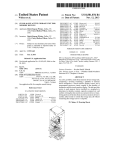
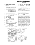
FIG. 1a is a block diagram of a multi-source television
not receive local network or local independent channels. In
program and television schedule guide system with multiple
order to provide these missing local channels, some DBS
receivers are capable of automatically switching between the
DBS satellite input and a local input. This is accomplished by
placing the IRD box between the television (or a VCR con
nected to the television) and the local line (local cable or local
antennae). When a local channel is selected by the user, the
IRD box automatically removes DBS from service and
becomes a bypass for the local input. A user can select a local
45
sources connected directly to the television;
FIG. 1b is a block diagram of a multi-source television
program and television schedule guide system with the mul
tiple sources connected directly to the coordinator;
FIG. lc is a block diagram of a television program and
television schedule guide system with DBS and cable as
50
source dcviccs;
FIG. 1d is a block diagram of a television program and
channel either manually or with a remote control. Access to
television guide system which has DBS, the coordinator, and
locally available channels is crucial because the majority of
prime time viewing is on those local networks.
the television tuner all within the same IRD box;
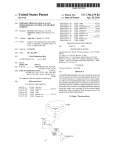
FIG. 2 is an example of an on-screen display of a schedule
In contrast, if a user is receiving television channels from
both cable and a local antenna sources, then the scenario is
55
information;
different. If the user’ s television has multiple television input
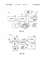
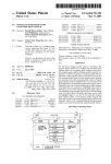
FIG. 3 is an exemplary process ?ow chart for automatic
tuning; and
ports, then these two sources can easily be attached to the two
input ports. This solution works well as long as the number of
sources does not become greater than the number of televi
grid guide that has been assembled from the television guide
FIG. 4 is an exemplary process ?ow chart for automatic,
60
unattended recording.
sion input ports.
If the user’s television does not have multiple inputs, then
DESCRIPTION OF SPECIFIC EMBODIMENTS
a manual switch box attached to the multiple sources and to
the television input can be utilized. This solution forces the
The present invention provides a tuning scheme which
user to manually switch between one source and another 65 coordinates television programs and television schedule
depending on which channel is desired. For example, if the
guide information. This television schedule guide informa
user wants the local news, which is available from the local
tion can be received from numerous sources. As stated above,
US 8,424,040 B2
3
4
these sources include an incoming cable line (e.g., on a coax
used by a viewer to tune the television and conduct other
cable), satellite broadcasts, a dedicated telephone line (e.g.,
twisted pair), and any other medium capable of transmitting a
box 26, and DBS is provided via IRD box 28. Antennae 34 on
signal. In the preferred embodiment, television channel
television 22 may be used as an additional source of television
broadcasts are received from at least two separate sources
broadcasts along with cable box 26, IRD box 28, and other
inputs 30. In one typical embodiment, antenna 34 and cable
operations. In this embodiment, cable is provided via cable
such as (1) cable and a satellite dish, or (2) two different
satellites, or (3) local cable and DBS sources. The schedule
information is provided with a source identi?er which iden
ti?es that schedule information as being from a particular
source. The schedule information is sorted and displayed in
box 26 are “local” sources. Other inputs 30 can include mul
tiple satellite sources. When multiple satellite sources are
present, coordinator 20 switches between the available satel
lite sources by automatically moving the user’s satellite dish
or switching between satellite dishes. In order to automati
cally move the satellite dish, a memory within IRD box 28
tracks the position of the DBS satellite dish in relation to
an organized fashion to the user.
When a user selects a show or channel located on one of the
displayed channels within a displayed guide, the system reads
the source identi?er associated with that show or channel. In
satellite sources which are available via the DBS satellite
the preferred embodiment, the system then carries out an
automatic switching/tuning process that switches the input to
dish. The IRD box 28 then automatically positions the DBS
the television (either RF or video) to a source device. Source
by the IRD box 28.
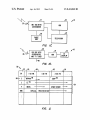
Coordinator 20 includes processor (CPU) 36 and memory
(RAM) 38. The coordinator is connected to and controls
infrared (IR) emitter(s) 40. IR receiver 39 is connected to
coordinator 20 and receives input from the remote. IR
emitter(s) 40 can be replaced by, for example, a bus interface
satellite dish such that the desired satellite source is received
devices include DBS, cable box, television tuner, etc. The
system then tunes to the required channel for the desired
show. Additionally, the source identi?er can be utilized to
20
switch between various devices automatically when unat
tended VCR programming is desired. Furthermore, when
program information is received from multiple satellite
sources and a desired channel is selected, the present inven
tion can, in one embodiment, automatically move the custom
er’s satellite dish such that the customer receives the desired
program from the associated source. The present invention
then tunes to the correct channel.
In creating a merged television guide, a channel map is
created which identi?es the channels available on the mul
tiple sources, and identi?es their source. For example, in the
case of DBS/local channel implementations, a channel map is
or an RF transmitter. The IR emitter(s) 40 controls one or
more ofIRD box 28, television 22, VCR 24, cable box 26, and
25
30
VCR 24, cable box 26, and/or other devices. Because coor
dinator 20 has the ability to simulate a remote controller,
coordinator 20 can be placed in the cable box 26, VCR 24,
television 22, stand alone unit 20, or a satellite receiver.
Remote control 32 is a hand-held remote controller for
controlling coordinator 20. In the preferred embodiment,
created with both local cable and DBS channels merged. The
local channels and the DBS channels are tagged with a source
identi?er. When the user/consumer selects a non-DBS chan
other inputs 30. Thus, IR emitter 40 acts as a remote control
device by emulating remote control signals of television 22,
35
remote control 32 is provided with an IR transmitter which
controls the coordinator via IR receiver 39. Other remote
controls, not shown in FIG. 1a, can be used for manually
nel from the guide, the integrated receiver decoder unit (IRD
box) for the satellite switches the IRD to couple the local
controlling television 22, VCR 24, cable box 26, IRD box 28,
and other inputs 30. Although, in a preferred embodiment,
cable to the receiver. The system then tunes the television
tuner or other tuning device to the required channel. If a DBS
coordinator 20 performs all the necessary control functions of
the system. In a preferred embodiment, remote 32 works with
coordinator 20 and emitter 40 to control the various devices in
FIG. 1a. For example, as the user adjusts the volume control
on remote 32, coordinator 20 emits signals through IR emitter
40 to adjust the volume in television 22.
IRD box 28 receives television programs along with other
information via, in one embodiment, satellite dish 29. IRD
box 28 then provides program schedule information to the
system. The schedule information is added to the transmitted
signal by the DBS service provider or a company under
contract. Examples of DBS service providers include Direct
TV and USSB. This program schedule information (or guide)
channel is later selected, the system switches the IRD to
couple the satellite receiver/decoder to the receiver. The sys
40
tem then tunes the DBS tuner to the selected DBS channel. In
the case of, for example, cable and antenna inputs, the system
switches to the correct video input and then tunes the televi
sion tuner to the required channel for receiving the selected
45
source. Thus, automatic access to multi-source television
schedule guide information is provided.
In another embodiment of the present invention, the user
can utilize the system to switch between destination devices.
For example, information/programs received from one of the
50
may also include a channel map that contains the channel
information which is available on a particular source. Infor
multiple sources could be displayed on a computer screen or
played on a stereo. Additionally, several destination devices
can be used in conjunction with each other. For example, an
FM radio station playlist could be shown on a computer
monitor or television display, and the songs selected from that
playlist could be later recorded on an audio recorder. Still
55
mation associated with the DBS guide is saved in the IRD box
receiver’s RAM 42 or downloaded. Similarly, program guide
information can be received through cable box 26, other
inputs 30, antennae 34, and/ or through any other transmission
further, the system could be used to couple audio TV outputs
medium (e. g., dedicated twisted pair telephone line). Each of
to a stereo system. Thus, the present invention is not limited to
these sources may also be provided with television schedule
data within the signal transmitted by the service provider.
television systems.
FIG. 1a illustrates in simpli?ed form an example of a
60
Coordinator 20 ?nds and sorts the program guide informa
tion available in system 10. In order to receive the required
television guide information, coordinator 20 is connected to
the source(s) of this information. For example, if the channel
map information is provided by a dedicated twisted pair tele
65
phone line, then that telephone line is input 43 to coordinator
multi-source television schedule guide system 10 with mul
tiple sources connected directly to a television 22. As shown,
multi-source television program and television schedule
guide system 10 operates under the control of coordinator 20.
Television 22 andVCR 24 are provided with input from cable
box 26 and IRD box 28. Other inputs 30 may also be supplied
to the television 22 and/or VCR 24. A remote control 32 is
20. Guide information can be provided from any commer
cially available medium and can apply to all or several of the
US 8,424,040 B2
5
6
available sources. In the preferred embodiment, television
been mixed, sorted, organized, etc., is received in a format
which is ready for immediate display. Less memory is
required within the coordinator in this latter situation because
only the screen/grid being viewed needs to be saved. For
guide information is provided via the vertical blanking inter
val on an available television channel. In FIG. 1a, the source
devices along with coordinator 20 are coupled to television
22. Thus, coordinator 20 receives the program guide infor
mation via telephone line 43, and television 22 receives the
television programs from the multiple sources. In addition,
television 22 receives the program guide information from
coordinator 20.
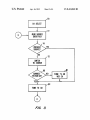
In another embodiment of the present invention, coordina
tor 20 receives all the source device inputs directly. FIG. 1b is
example, in this latter situation, if a user wishes to view a grid
guide which is four hours long, only four hours worth of
information needs to be saved within RAM 38. This ready
for-immediate-display format can also be provided in a sepa
rate data stream via a different medium or on a television
channel.
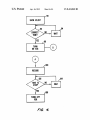
FIG. 2 is an example of an on-screen display of a schedule
grid guide that has been assembled from the television guide
information. The grid guide of the present invention also
refers to and includes theme guides, channel guides, and other
guides which display program information. In the preferred
a block diagram of a multi-source television program and
television schedule guide system with the multiple sources
connected directly to the coordinator. In this embodiment,
coordinator 20 switches between the multiple sources 26, 28
and 30 and then outputs the information from the desired
20
embodiment, after coordinator 20 has collected and sorted all
the available program guide information, coordinator 20 gen
erates the grid guide set forth in FIG. 2 for display on televi
sion 22. This grid guide can also be generated within the IRD
box, a satellite receiver, the television, the VCR, a central
25
the reference numeral 50, provides a line up of all channels or
a selection of channels 52 along with a description of the
shows 54 available on those channels at certain times 56. For
example, channel 2 58 has BATMAN 60 as a show from 1:00
source to television 22 or to another destination device. This
arrangement allows for a single input to television 22. Coor
dinator 20 inputs program guide information along with tele
vision programs to television 22 via line 44 or through VCR
of?ce location, etc. The grid guide, designated generally with
24 via lines 45 and 46. Other possible destination devices for
the present invention are computer monitors, audio recorders,
facsimile machines, printers, memory, etc.
In yet another embodiment of the present invention, DBS
(via IRD box 28) and cable (via cable box 26) are source
devices which are connected in series to television 22. FIG. lc
is a block diagram of a television program and television
schedule guide system with DBS and cable as source devices.
In this arrangement, the coordinator is located within IRD
box 47, and no IR emitter is needed. IRD box 47 inputs to
television 22 directly or through VCR 24. When DBS is
pm. to 2:00 pm. and SOAP 62 as a show from 2:00 pm. to
2:30 pm. A theme, or channel, or random, etc. listing can be
30
betical order, or (2) channels are in an order associated with
their particular source, or (3) channels are in a mixed order
programmed by a user, or (4) channels are in any other
removed from service by the coordinator within IRD box 47,
cable box 26 inputs to television 22.
FIG. 1d is a block diagram of a television program and
television guide system which has DBS, the coordinator, and
35
the television tuner all within the same IRD box. In this
additional embodiment, no cable source is present, and DBS,
the coordinator and the television tuner are all located within
IRD box 48. Thus, no emitter is needed. The coordinator
switches between DBS and other available source(s) received
delete and activate the channels displayed in grid guide 50,
40
the user can determine whether to have one of the ABC
45
channels, both of the ABC channels, or neither of the ABC
channels. The user’ s choice is entered into coordinator 20 via
remote control 32. In an alternative embodiment, coordinator
20 may automatically note duplicate network names and
delete one of the duplicates. In addition, coordinator 20 is
on line 49. After the coordinator has switched and tuned to the
played on television display 23 or recorded by VCR 24. The
VCR set forth in FIGS. 1a-1d is optional. Additionally, the
capable of automatically lining up channels based on user’s
habits. If this mode for the automatic arrangement of channels
or the VCR.
Various formats can be used for the television schedule
information. For example, data packets comprising a header
section and information section can be received and sorted
with other, more complex data packet formats. In the pre
ferred embodiment, coordinator 20 takes the television
arrangement. When multiple sources are used for receiving
television channels, an overlap of channels sometimes
occurs. For example, both cable and DBS may carry the
network ABC, but cable may have ABC on channel 6 and
DBS may have ABC on channel 7. By having the ability to
desired channel, (as described below) that channel is dis
DBS receiver and tuner could be located within the television
used instead of the grid guide shown in FIG. 2.
If a grid guide is used, the lineup of channels 52 can be
arranged such that (1) channels are in numerical and/or alpha
50
is selected by the user, an algorithm based on user habits is
used to determine the channel order 52. Therefore, any
desired arrangement for the lineup of channels 52 is available.
In the preferred embodiment, the user displays grid guide
schedule information from the available source(s) or a data
50 by pressing a guide button on remote control 32. Coordi
input line and sorts/mixes it. For example, coordinator 20
nator 20 responds to the initial pressing of the guide button by
may receive program schedule information via the vertical
blanking interval in a television channel or via a transponder
of DBS.
In order to sort/mix the available schedule information,
55
coordinator 20 ?rst creates a structured framework and then
saves the received data in that structured framework. This
structure framework includes several levels for organized
data storage. After the levels of the framework are prepared by
automatically tuning to the channel or device which carries
grid guide 50, or overlaying a grid guide in a current broad
cast. When the user is done with grid guide 50, the user
presses the guide button again (or an exit button) and coordi
nator 20 (I) automatically returns to the channel or source last
60
viewed by the user or (2) removes the overlay. The technique
utilized by coordinator 20 for automatic tuning is described
further below.
coordinator 20, pointers are utilized to save data within appro
In order to track which channels are available from which
priate levels of the structure.
In an alternative arrangement, the sorting/mixing of pro
sources, a source identi?er is located on each channel. Each of
gram schedule information is done in a separate location and
then provided to system 10, for example, on a satellite chan
nel. Thus, program schedule information, which has already
65
the source identi?ers may be included in the channel guide
information, or the source identi?ers may be added by the
system based on the origin of the channel guide information.
Therefore, if these data are not already provided, coordinator
US 8,424,040 B2
8
7
20 attaches the appropriate identi?ers to the received channel
guide information. For example, if BATMAN 60 is received
through IRD box 28, than BATMAN 60 will have a source
identi?er for identifying the IRD box 28 located on its chan
nel 58. In the preferred embodiment, the source identi?er is
To further illustrate the process set forth in FIG. 3, the
following example is provided. In this example, IRD box 28
has channels 100-200 available and is presently the input
source to television 22 (see FIG. 10). Additionally, cable box
26 is an input to IRD box 28 (see FIG. 10). A user selects
BATMAN 60 on channel 2 58 at step 70. The selected show is
not displayed to the user. If desired, the user can program
coordinator 20 to display which source the channel is associ
ated with. For example, channels which come from cable box
26 can be colored red in grid guide 50 and channels available
from IRD box 28 can be the color green; thus, if desired, the
user can easily identify which source is associated with each
channel.
Remote 32 can be utilized by the user to program coordi
available on a channel from cable box 26. Coordinator 20
reads the source identi?er associated with the selected show
and determines that channel 2 is from cable box 26 at step 72.
Coordinator 20 then determines that the present source is IRD
box 28 at step 74. Therefore, a switching of sources must
occur. As set forth above, when DBS is no longer the selected
source, IRD box 28 allows cable box 26 to send signals
nator 20 or to move between different channels, times and
shows in grid guide 50. Moreover, remote control 32 can be
used to select a certain channel or show (1) for displaying
additional information associated with a particular show, (2)
for tuning to a particular channel or show, or (3) for automati
cally recording a particular show. Remote control 32 can also
be used for adjusting the volume or other features of televi
through an internal relay (electronic or mechanical) within
20
sion 22 or other devices. The additional information associ
ated with a particular show may include a short description of
as required for input from cable box 26 (see step 80). Since
that show. For example, a short description of the story
included in a sitcom may be provided. To display this addi
tional information, coordinator 20 accesses the desired infor
mation in RAM 38 or switches to a different input of data, and
television 22 is already on channel 3, no change is made to the
television channel (see step 84). Coordinator 20 then utilizes
25
displays the additional information in an appropriate place
within grid guide 50. In the preferred embodiment, this addi
tional information is displayed (1) in an overlay, or (2) as a
pull down window under the selected show, or (3) as a de?ned
IR emitter 40 to tune cable box 26 to the desired channel 2 at
step 84. As stated above, step 82 and step 84 can occur
simultaneously. The program on is then displayed on televi
sion 22, and the process set forth in FIG. 3 is complete. In
other embodiments, the television tuner will be used to select
30
information window at the top or the bottom of the screen.
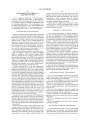
FIG. 3 is an exemplary process ?ow chart for automatic
tuning. To begin automatic tuning, the user selects a certain
channel or show at step 70. The selection may be made by, for
example, scrolling a cursor to a desired show and striking the
“enter” key, or entering a channel number using remote 32.
IRD box 28 to television 22. Therefore, coordinator 20 uti
lizes IR emitter 40 to deactivate or decouple DBS at step 78.
IRD box 28 is inputted to television 22 through channel 3 of
television 22. In the present arrangement, cable box 26 is also
connected through channel 3 of television 22. Coordinator 20
may then check television 22 to ensure that it is on channel 3,
from numerous inputs from the sources, or a mixed system
may provide that the television tuner is used for some sources,
and the source tuner is used for other sources.
FIG. 4 is an exemplary process ?ow chart for automatic,
unattended recording. To begin automatic, unattended
35
Coordinator 20 then reads the source identi?er at step 72 and
determines if the present input to television 22 is the source
associated with the source identi?er (see step 74). If the
recording, the user selects a television show for recording
with remote 32. In order to provide the automatic recording of
the selected program, VCR 24 is automatically turned “on”
(along with the activation of the VCR’ s record feature) at the
appropriate time and then turned “off” when the show is
present input source to television 22 is the same as the source 40
complete. The tuning process used for automatic recording is
associated with the source identi?er, then coordinator 20
tunes that particular source to the desired channel at step 84.
If the present source is not the source associated with the
source identi?er, then the system switches sources to the
proper source. For example, processor 36 may cause IR emit
ter 40 to send out a signal which switches from the present
the same as the process set forth for automatic tuning (see
FIG. 3), but the VCR is tuned to the correct channel rather
than the television.
As set forth in FIG. 4, after the user selects a show at step
90, the coordinator checks to see if the beginning time for that
45
show has passed (see step 92). If the beginning time has not
passed, coordinator 20 waits at step 94. When the correct time
source, and which activates or switches to the source associ
ated with the source identi?er. The desired channel or show
then serves as the source inputting information to television
22. Coordinator 20 then determines if the correct television
channel or input for that particular source (the source associ
ated with the source identi?er) is activated at step 80. If the
correct television channel or input is not activated, then the
appropriate tuner in the system is tuned to the proper channel.
For example, IR emitter 40 may be used to tune the television
to the desired television channel at step 82. Alternatively, step
(the program’s starting time) does occur, VCR 24 is turned
50
for automatic tuning is indicated by B. During the tuning
55
sequence for automatic recording, the VCR, rather than the
television, is tuned to the correct channel (see steps 80 and
82). When the process ?ow set forth in FIG. 3 is complete, as
indicated by A, coordinator 20 utilizes IR emitter 40 to acti
vate the recording feature of the VCR at step 100 in FIG. 4.
60
This causes VCR 24 to record the selected program. Coordi
nator 20 then checks to see if the end time of the show matches
the present time at step 102. If the show is not over, coordi
nator 20 waits at step 104. When the end time for the show
80 could be removed, and coordinator 20 would then always
tune or re-tune to the required channel, thereby con?rming
that television 22 is on the correct channel. After (or simul
taneous with) the activation of the correct television channel
or input associated with the desired source, IR emitter 40
tunes the receiver in that source to the desired channel at step
84. The desired broadcast is then displayed on television 22.
If a program is input to television 22 and/or VCR 24 via
coordinator 20 (see FIG. 1b), then no tuning is needed for the
television and/ or VCR. Therefore, in this latter arrangement,
steps 80 and 82 are not present.
“on” (see step 96) and coordinator 20 acts as though auto
matic tuning has occurred. Therefore coordinator 20 reads the
source identi?er associated with the channel providing the
selected show at step 72 (see FIG. 3). This transition between
the process ?ow for automatic recording and the process ?ow
matches the present time, IR emitter 40 stops recording the
65
show and then turns “off” the VCR at step 106. This scheme
allows for the unattended, automatic recording of any show
available from any source coupled to VCR 24.
US 8,424,040 B2
10
7. The method of claim 1 further comprising:
storing a signal source identi?er for each of the plurality of
program listings, each signal source identi?er identify
ing one of the ?rst transmission scheme and the second
transmission scheme.
8. The method of claim 1 further comprising:
receiving a user selection selecting one of the plurality of
In another embodiment of the present invention, coordina
tor 20 is located Within IRD box 28, and coordinator 20
handles the switching and tuning required for DES and cable
sources Without utilizing an IR emitter. When the user/con
sumer selects a non-DBS channel from the guide, the coor
dinator sWitches from the integrated receiver decoder unit for
the satellite to the cable (if the source is originally DES), and
program listings;
proceeds to tune the television tuner, or television tuner and
cable box to the required channel. If a DBS channel is later
retrieving a signal source identi?er that identi?es one of the
?rst transmission scheme and the second transmission
selected, the system sWitches back to the integrated receiver
scheme that corresponds to the selected program listing;
decoder unit and tunes to the required DBS channel. This
and
receiving a television signal from one of the ?rst tuner and
arrangement allows for the coordinating of multi-sources
Without the need for an IR emitter.
With the assistance of coordinator 20, a user does not have
to manually select a television program source or manually
tune to a desired channel or program. Moreover, With the
the second tuner Which uses the identi?ed transmission
scheme.
9. The method of claim 1 Wherein the ?rst source device
and the second source device are selected from the group
automatic receiving, grid guide generating, sWitching, and
consisting of a cable, a broadcast source, an antenna source, a
terrestrial source, a satellite source, and a direct broadcast
tuning available in system 10, there is little if any manual
interaction from the end user or customer.
20 satellite source.
While a full and complete disclosure of the invention has
been provided herein above, it Will be obvious to those skilled
in the art that various modi?cations and changes may be
made.
10. The method of claim 1 further comprising:
identifying the transmission scheme used to transmit a
television program corresponding to one of the plurality
of program listings.
25
What is claimed is:
1. A method used in a user equipment device having a ?rst
tuner for receiving a ?rst plurality of television programs
mission scheme used to transmit a television program corre
sponding to one of the plurality of program listings includes
displaying a transmission scheme identi?er in a ?rst color that
corresponds to the ?rst program listing, and displaying a
transmitted from a ?rst source device using a ?rst transmis
sion scheme and a second tuner for receiving a second plu
rality of television programs transmitted from a second
source device using a second transmission scheme Which is
different from the ?rst transmission scheme, the method com
11. The method of claim 10 Wherein identifying the trans
30
transmission scheme identi?er in a second color that corre
sponds to the second program listing.
12. The method of claim 1 further comprising:
displaying the ?rst program listing; and
prising:
displaying, in response to a user selection, the second pro
receiving a plurality of program listings including a ?rst
program listing corresponding to one of the ?rst plural
ity of television programs and a second program listing
corresponding to one of the second plurality of televi
35
restrial or satellite.
14. The system for use in a user equipment device having a
sion programs;
displaying a guide having the plurality of program listings;
40
plurality of program listings, selecting one of the ?rst
tuner and the second tuner, Wherein
the ?rst tuner is selected When the selected program
45
listing is the second program listing; and
50
in response to receiving a user selection selecting one of the
55
source device.
4. The method of claim 1 further comprising merging the
?rst program listing and the second program listing to form
5. The method of claim 1 further comprising:
order.
6. The method of claim 1 further comprising:
automatically deleting duplicate program listings from the
plurality of program listings.
plurality of program listings, means for selecting one of
the ?rst tuner and the second tuner, Wherein
the ?rst tuner is selected When the selected program
listing is the ?rst program listing, and
the channel guide.
mixing and sorting the plurality of program listings in a
desired order; and
displaying the plurality of program listings in a desired
means for receiving a plurality of program listings includ
ing a ?rst program listing corresponding to one of the
?rst plurality of television programs and a second pro
gram listing corresponding to one of the secondplurality
of television programs;
means for displaying a guide having the plurality of pro
gram listings;
device; and
the second program listing is received from the second
sion scheme and a second tuner for receiving a second plu
rality of television programs transmitted from a second
source device using a second transmission scheme Which is
different from the ?rst transmission scheme, the system com
prising:
the second tuner is selected When the selected program
tuning the selected tuner to the television program
received by the selected tuner.
2. The method of claim 1 Wherein the plurality of program
listings are received from a single data source.
3. The method of claim 1 Wherein:
the ?rst program listing is received from the ?rst source
?rst tuner for receiving a ?rst plurality of television programs
transmitted from a ?rst source device using a ?rst transmis
in response to receiving a user selection selecting one of the
listing is the ?rst program listing, and
gram listing.
13. The method of claim 1, Wherein one of the ?rst trans
mission scheme and the second transmission scheme is ter
the second tuner is selected When the selected program
60
listing is the second program listing; and
means for tuning the selected tuner to the television pro
gram received by the selected tuner.
15. The system of claim 14, Wherein the plurality of pro
gram listings are received from a single data source.
16. The system of claim 14 Wherein:
the ?rst program listing is received from the ?rst source
device; and
US 8,424,040 B2
11
12
the second program listing is received from the second
means for receiving a television signal from one of the ?rst
tuner and the second tuner Which uses the identi?ed
transmission scheme.
22. The system of claim 14, Wherein the ?rst source device
and the second source device are selected from the group
source device.
17. The system of claim 14 further comprising:
means for merging the ?rst program listing and the second
program listing to form the channel guide.
18. The system of claim 14 further comprising:
means for mixing and sorting the plurality of program
listings in a desired order; and
means for displaying the plurality of program listings in a
desired order.
19. The system of claim 14, Wherein said means for dis
playing a program guide further comprises:
means for automatically deleting duplicate program list
consisting of a cable, a broadcast source, an antenna source, a
terrestrial source, a satellite source, and a direct broadcast
satellite source.
23. The system of claim 14, further comprising:
means for identifying the transmission scheme used to
transmit a television program corresponding to one of
the plurality of program listings.
24. The system of claim 23 Wherein the means for identi
fying the transmission scheme used to transmit a television
program corresponding to one of the plurality of program
listings includes means for displaying a transmission scheme
identi?er in a ?rst color that corresponds to the ?rst program
listing, and means for displaying a transmission scheme iden
ti?er in a second color that corresponds to the second program
ings from the plurality of program listings.
20. The system of claim 14 further comprising:
means for storing a signal source identi?er for each of the
plurality of program listings, each signal source identi
?er identifying one of the ?rst transmission scheme and
the second transmission scheme.
21. The system of claim 14 further comprising:
20
25. The system of claim 14 further comprising:
means for displaying the ?rst program listing; and
means for receiving a user selection selecting one of the
means for displaying, in response to a user selection, the
plurality of program listings;
means for retrieving a signal source identi?er that identi?es
one of the ?rst transmission scheme and the second
transmission scheme that corresponds to the selected
program listing; and
listing.
second program listing.
25
26. The system of claim 14, Wherein one of the transmis
sion schemes is terrestrial or satellite.
*
*
*
*
*
UNITED STATES PATENT AND TRADEMARK OFFICE
CERTIFICATE OF CORRECTION
PATENT No.
; 8,424,040 B2
APPLICATION NO.
: 11/841521
DATED
INVENTOR(S)
: April 16, 2013
: Klosterrnan
Page 1 of 1
It is certified that error appears in the above-identi?ed patent and that said Letters Patent is hereby corrected as shown below:
On the Title Page:
The first or sole Notice should read -
Subject to any disclaimer, the term of this patent is extended or adjusted under 35 U.S.C. 154(b)
by 1096 days.
Signed and Sealed this
Twenty-seventh Day of August, 2013
Teresa Stanek Rea
Acting Director 0fthe United States Patent and Trademark O?ice
UNITED STATES PATENT AND TRADEMARK OFFICE
CERTIFICATE OF CORRECTION
PATENT No.
; 8,424,040 B2
APPLICATION NO.
: 11/841521
DATED
INVENTOR(S)
: April 16, 2013
: Brian Lee Klosterman
Page 1 of 1
It is certified that error appears in the above-identi?ed patent and that said Letters Patent is hereby corrected as shown below:
In the Claims:
Column 9, claim 4, line 59, delete “channel”.
Column 10, claim 14, line 39, change “The” to -- A --.
Column 11, claim 19, line 12, delete “program”.
Signed and Sealed this
Ninth Day of September, 2014
WMZ44L_
Michelle K. Lee
Deputy Director 0fthe United States Patent and Trademark O?ice


![AGIVEN PROGRAM ]](http://vs1.manualzilla.com/store/data/005708142_1-ae1c6d6b32e7a9016e2dede042b38772-150x150.png)


![El WE]](http://vs1.manualzilla.com/store/data/005973526_1-5126190d8f2880fb7d5b7ddc41b9f31a-150x150.png)