1
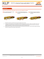
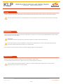
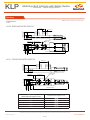
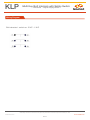
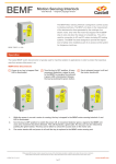
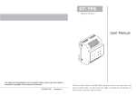
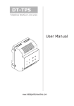
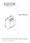
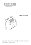
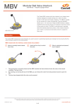
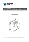
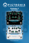
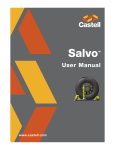
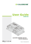
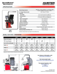
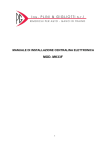
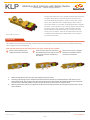
KLP
Multi Key Bolt Interlock with Safety Switch
User Manual - Original Language Version
The KLP bolt interlock is a key operated mechanical bolt interlock
complete with position monitoring electrical contacts for the
control of electrical switchgear or valves. The KLP lock comes
with a 16 mm diameter bolt of variable length, that is used to
control the rotation or movement of operating handles or toggles.
The KLP1 comes with 2N/C 1N/O 10 amp contacts and the KLP2
has 4N/C 2N/O 10 amp contacts, these are used to provide
remote indication of the bolt position or to switch the control
circuitry on the machine. The locks are manufactured in brass
or stainless steel making them ideally suited to use in harsh or
corrosive environments.
KLP2-FSB-1S-0-FR-4-D
Operation
The Castell KLP bolt interlocks with safety switches are used in switchgear control to break circuitry and inhibit movement of
cams, toggles or levers simulateously.
KLP multi key bolt interlock with safety switch, rear entry, exchange key condition
1
Key A is free, while key B is
trapped and bolt is retracted.
A
B
2
Insert and turn key A to extend the 3
bolt. Release key B to trap key and
change the contacts condition of
the switch.
B
A
Key B is free, key A is trapped
and bolt is extended. Switch
contacts are reversed.
A
B
1.
While the side bolt is retracted, key B is trapped and key A is free.
2.
Inserting and turning key A in the KLP bolt interlock drives the bolt to extended position and allows to turn
and release key B. This changes the contacts condition in the KLP switch. The extended bolt locks the power
disconnector in the OFF position. Key B can now be taken by personnel into machine area.
3.
With key B released and key A trapped in the KLP, the bolt stays extended, ensuring the disconnector is in the
safe condition.
While every effort has been made to ensure the accuracy of the information provided, no liability can be taken for any errors or omission.
Castell Safety International Limited reserves the right to alter specifications and introduce improvements without prior notice.
www.castell.com
U-KLP-001-E Issue 2
1 of 7
KLP
Multi Key Bolt Interlock with Safety Switch
User Manual - Original Language Version
Operation
KLP multi key bolt interlock with safety switch, rear entry, double key condition
1
Key A and B are trapped, while
the bolt is retracted.
B
A
2
Turn and release both keys, to
drive the bolt and change switch
condition.
B
A
3
Both keys are free and bolt is
extended. Switch contacts are
reversed.
B
A
1.
While the side bolt is retracted and key B is trapped, key A is free.
2.
Turning and releasing key A in the KLP bolt interlock changes the contacts condition in the KLP switch and
enables the rotation of key B to drive the bolt. The extended bolt locks the power disconnector in the OFF
position. Both keys can now be taken by the personnel to the machine area.
3.
With both keys released, the bolt stays extended, ensuring the disconnector is in the safe condition until both
keys are inserted and turned KLP bolt interlock.
While every effort has been made to ensure the accuracy of the information provided, no liability can be taken for any errors or omission.
Castell Safety International Limited reserves the right to alter specifications and introduce improvements without prior notice.
www.castell.com
U-KLP-001-E Issue 2
2 of 7
KLP
Multi Key Bolt Interlock with Safety Switch
User Manual - Original Language Version
Usage
The KLP multi key bolt interlock with safety switch should be used to allow safe control of valves or disconnect switches.
The KLP multi key bolt interlock is not designed for security purposes, such as a safe or external access to a building.
Installation
The housing of the KLP bolt interlock can be mounted either to a panel or on a surface using suitable fasteners. Please refer to
drawing on page 4 for more details
IMPORTANT:
The interlock should be mounted using anti-tamper fasteners to prevent unauthorised removal.
The KLP bolt interlock must be installed by a competent and qualified person who has read and understood these
instructions. Please retain this document in your technical file.
Force required to shear lock bolt is 30KN for stainless steel and 19KN for brass interlocks.
Maintenance
Periodic visual checks should be carried out by the site manager / safety officer.
Do not lubricate lock barrel with oil or grease, use CK Dry Powder Graphite if necessary.
In case of defects beeing detected please contact your nearest Castell Support Department for further actions.
Please see Contact section for contact details.
While every effort has been made to ensure the accuracy of the information provided, no liability can be taken for any errors or omission.
Castell Safety International Limited reserves the right to alter specifications and introduce improvements without prior notice.
www.castell.com
U-KLP-001-E Issue 2
3 of 7
KLP
Multi Key Bolt Interlock with Safety Switch
User Manual - Original Language Version
Technical Data
Temperature rating
-25°C ice free to +55°C
Type of mounting
panel or surface mount using suitable fasteners (please refer to drawing on page 4 for more details)
KP1: Front of board mount = 0,8 kg / back on board mount = 0,6 kg
Weight
KP2: Front of board mount = 0,8 kg / back of board mount = 1 kg
Material
Brass/Stainless steel
Switch approvals
CE, CCC, cCSAus, IP65
MTTF Certification
Available on request
Application
Castell KLP bolt interlocks with safety switches are
used as a part of a safety system, typically in switchgear
applications.
The electrical supply of the machine is on, and the
protective doors to the hazardous area are locked. Both
keys are trapped in the KLP unit. Before entering the
machine area the disconnector lever needs to be rotated to
isolate the power to the machine. To lock the disconnector
lever in the safe position both keys in the KLP bolt interlock
need to be released. This extends the bolt of the KLP, locks
it in the extended position and changes the contacts in the
KLP switch. This is connected to a traffic light or another
display, indicating the access to machnine area can be
gained.
Machine power ON
Display
The removed keys are taken to the AI access interlocks to
Machine power OFF
open the doors. The power supply cannot be switched back
on while the keys are trapped in the access interlocks.
EC-Declaration
We, the manufacturers, declare that the components, detailed herein and placed on the market, comply with all the essential
health and safety requirements applying to them.
Empowered signatory:
Mr T.C. Whelan
Managing Director
While every effort has been made to ensure the accuracy of the information provided, no liability can be taken for any errors or omission.
Castell Safety International Limited reserves the right to alter specifications and introduce improvements without prior notice.
www.castell.com
U-KLP-001-E Issue 2
4 of 7
KLP
Multi Key Bolt Interlock with Safety Switch
User Manual - Original Language Version
Drawing
Dimensions:
Note: For safe mounting, use security screws
in mm
KLP2, REAR MOUNTED SWITCH
57.15 (2.25")
25.4 (1")
12.7 (.5")
52.56 (2.07") FSKLP
67.8 (2.67") QKLP
n34.9 (1.374")
4 Mounting Holes
mm (.275")
57.15 (2.25")
n15.88 (0.625")
28.6 (1.125")
66.4 (2.61")
44.45 (1.75")
15.88 (.625")
245.05 (9.65") Approx.
'L'
KLP1, FRONT MOUNTED SWITCH
12.7 (.5")
25.4 (1")
52.6 (2.07") FSKLP
67.8 (2.67") QKLP
57.15 (2.25")
4 Mounting Holes
Ø7mm (.275")
57.15 (2.25")
28.6 (1.125")
n15.88 (.625")
44.45 (1.75")
15.88 (.625")
'L'
219.04 (8.62") Approx.
L Dimension
Retracted bolt length (in mm)
Extended bolt length (in mm)
0
19,05
6,35
25,40
12,70
31,75
19,05
38,10
25,40
44,45
While every effort has been made to ensure the accuracy of the information provided, no liability can be taken for any errors or omission.
Castell Safety International Limited reserves the right to alter specifications and introduce improvements without prior notice.
www.castell.com
U-KLP-001-E Issue 2
5 of 7
KLP
Multi Key Bolt Interlock with Safety Switch
User Manual - Original Language Version
Wiring Diagram
Bolt retracted - switch on: 2 N/C - 1 N/O
While every effort has been made to ensure the accuracy of the information provided, no liability can be taken for any errors or omission.
Castell Safety International Limited reserves the right to alter specifications and introduce improvements without prior notice.
www.castell.com
U-KLP-001-E Issue 2
6 of 7
KLP
Multi Key Bolt Interlock with Safety Switch
User Manual - Original Language Version
Order Information
Product Type
Part Number
KLP
Example
KLP
1
3
4
2
-
-
FS
B
Isolation Key Symbol
(exchange key condition)
A
7
2
or
-
1S
B
8
5
6
-
-
0
-
7
8
FR
-
4
-
Personnel Key Symbol
(exchange key condition)
or
Primary Key Symbol
(double key condition)
Secondary Key Symbol
(double key condition
1
Switch specification
1 = 2NC/1NO (1 switch) (2)
2 = 4NC/2NO (2 switches) (2)
2
Lock portion type
FS (1) / Q (1)
3
Material
B = Brass / S = Stainless steel
4
Secondary lock portion(s)
1S / 2S / 3S / 4S / 5S or 6S = 1 / 2 / 3 / 4 / 5 or 6
Secondary lock portions are provided for personnel keys, primary
secondary lock portions respectively
lock posrtion for the isolation key
6
L Dimension (bolt length when retracted) in mm
0 / 6,4 / 12,7 / 19,1 / 25,4
6
Switch entry
FR = Front entry switch / RE = Rear entry switch (3)
7
Form
1 / 2 / 3 / 4 (4)
8
Key condition
E = Exchange key condition /
D = Double key condition (removal of all keys)
7
Lock portion symbol:
Isolation key (for exchange key condition)
Primary key (for double key condition, located next to the bolt)
FS (1) up to 3 characters / Q (1) up to 6 characters
8
Lock portion symbol:
Personnel key (for exchange key condition)
FS (1) up to 3 characters / Q (1) up to 6 characters
Secondary key (for double key condition - this key drives the bolt)
(1)
(2) Switch specification
FS - Lock type Q - Lock type
Up to 3 characters
(4)
1
Up to 6 characters
1
D
(3) Switch entry
2
RE
FR
Form
2
3
4
Special construction available upon enquiry
Contact Information
Castell Safety International Ltd.
The Castell Building
217 Kingsbury Road
London, England NW9 9PQ
Castell Safety International Ltd.
Oskar-Jäger-Strasse 137
50825 Köln
Germany
Castell Interlocks Inc.
Suite 800
150 N Michigan Avenue,
Chicago, Illinois 60601
USA
Castell Safety China
Building 1, No. 123,
Lane 1165, Jindu Road,
Minhang District,
Shanghai 201108, China.
t: +44 (0) 20 8200 1200
f: +44 (0) 20 8905 9378
e: [email protected]
t: +49 (0) 221 1694 794
f: +49 (0) 221 1694 795
e: [email protected]
t: +1.312.360.1516
f: +1.312.268.5174
e: [email protected]
t: +86 21 61519023
f: +86 21 61519030
e: [email protected]
While every effort has been made to ensure the accuracy of the information provided, no liability can be taken for any errors or omission.
Castell Safety International Limited reserves the right to alter specifications and introduce improvements without prior notice.
www.castell.com
U-KLP-001-E Issue 2
7 of 7