1
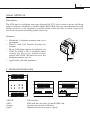
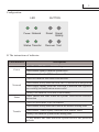
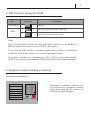
DT-GSM
telephone converter
User Manual
Please read this manual carefully before using the product you purchase, and
keep it well for future use.We reserve the right to modify the specification in
this manual at any time without notice.
1
About GSM Unit
Discription:
The GSM unit is a telephone converter designed for DT 2-wire system to divert calls from
outdoor station to telephone or mobile phone.With GSM unit,you can communicate with
outdoor visitor by your telephone or mobile phone which just like a remote control,you
can do the operation of talking,unlock and so on.
Features:
72
60 mm
1. Terminal Introduction
1 2 3 4 5 6
ON
SETUP
SETUP:
SIM:
Output:
Input:
mm
90 mm
• Maximum 3 telephone numbers can be set
on monitor.
• Must be with Call Transfer function for
monitor
• Divert Calls from monitor to telephone via
GSM ,the GSM is like a telephone,when
setting the diversion function,door
station calls GSM first,then divert to the
telephone number you set.
• Application:villa and apartment
SIM
OUTPUT INPUT
DIP switches.
SIM card slot ,the place to Install SIM card.
Output port,connect to Monitor.
Input port,connect to power supply.
2
Configuration:
LED
BUTTON
Power Network
Reset
Signal
Quality
Status Transfer
Recover Test
* The instructions of indicator:
LED indicator
Power
Descriptions
-LED off When the GSM not working
-LED flashes rapidly when the system error
-Always on when the GSM work normally
-LED off when the SIM card is not detected
-LED flashes slowly when the SIM card is detected but unregistered
Network
-LED flashes rapidly when the SIM card is detected and registered
successfully,but initialization unsuccessful
-Always on when the GSM kits work normally
Status
-LED flashes one time when the system receives the effective
instruction
-LED off When there is no call transfer
-LED flashes slowly when the GSM in the transfer waiting state
Transfer
-LED flashes 3 times rapidly when the GSM transfer failed
-Always on when the system in the talking state
* LED flashes one time when the system recover the password
defaults
3
* The instructions of button:
Button
Descriptions
-Press Reset button,it will reset GSM kits
Reset
Signal Quality
-Press Signal Quality button,it will show the signal strength
Recover
-Press Recover button,it will recover the password defaults
Test
-Press Test button,it will call the monitor 00
* NOTE:
Signal strength show:After press Signal Quality key, 4 LEDs off for a second,
then the GSM kits will use 4 LEDs to display signal strength(no signal: 4 LEDs
off; bad signal: only the LED of Power on; weak signal:only the LED of Power
& Network on; good signal: the LED of Power & Network & Status on; strong
signal:4 LEDs on)for a second, and 4 LEDs off again for a second later, it will
back to the start state.
2. Mounting
Step1: Mount the din rail to the
wall with screws ;
Step2: Pull down the mounting
buckle,then hang the unit on
din rail.
Din rail
Din rail
Mounting Buckle
Antenna
NOTE:A magnet installed on the antenna base, fixed on the
wall directly adsorbed iron (iron Fortunately, pre-installed on
the wall) place. In addition, the antenna should be installed
in the open place, there should be no obstructions around.
4
3. DIP Switches Setting for GSM
Bit
DIP1-DIP5
DIP6
Bit State
Description
1 2 3 4 5 6
Reserve
1 2 3 4 5 6
Set to on,it shows the system is partment.
1 2 3 4 5 6
Set to off, it shows the system is villa.
ON
ON
ON
Note:
Total 6 bits for DIP switches, to villa application, just Bit-6 is useful,Bit1 to
Bit5 are invalid. Bit-6 must be set to OFF in villa system.
Total 6 bits for DIP switches, to partment application, just Bit-6 is useful,Bit1
to Bit5 are invalid. Bit-6 must be set to ON in partment system.
In principle, whether it is a partment or villa, a 2-Wire system only install a
GSM. If you need to install multiple GSM, please contact the engineering staff.
4.Telephone Number Setting on Monitor
Touch screen monitors:
-Telephone Number-
1
2
3
1> _
4
5
6
2> _
7
8
9
3> _
0
Don’t divert calls
Divert if not answered
Divert simultaneously
Exit&save Exit&Unsave
• Maximum 3 telephone numbers can
be set,touch the telephone number
frame,then input the the number by
touching the digital keypad.
5
Button operation monitors:
GSM configure
1) 0
2)
3)
4)Divert mode select: 2
0:Not
1:Not Answer 2:Simulateously
Cancel
Edit
Save&Exit
• Maximum 3 telephone numbers can
be set,Use ▲ /▼ Button to move
upward / downward to select the
item,then press the MENU button to
edit.Use ▲ / ▼ Button to increase /
decrease the value,and use button
to input next digital,use button to
button to cancel the input. press
the MENU button again to finish the
edit operation.
Note:
• There are 3 types of divert modes:
• 1:Don't divert calls----calls from outdoor station will not be diverted.
• 2:Divert if not answered----outdoor station calls indoor monitor firstly,if nobody
answer the call within 25 seconds,the call will be diverted to the telephone number
you set. At this mode,the monitor will shut off immediatelly when GSM deverts
sucessfully,while it won't affect the communication between GSM and outdoor
station.Otherwise, the monitor can do the operation of monitoring,talking,and
unlocking.
• 3:Divert simutaneously----calls from outdoor station will be diverted to your
telephone immediately.At this mode,the monitor won't shut off when GSM deverts
sucessfully,but if the monitor answers the call at this time,GSM will quit absolutely.
5.Operation Instructions
Note: Divert function is activated in the following instructions
6
Item
Discription
Unlocking
• Input 1# on your telephone or mobile phone to
release the first lock
• Input 2# on you telephone or mobile phone to release
the second lock
Hanging up
• Input 9# on your telephone or mobile phone to hang
off absolutely
• Total divert calling time is more than 5 minutes
Calling next telephone
number
• 1:At least 2 telephone numbers must be set on
monitor
• 2:During communication between telephone and
outdoor station,"#" button has not been input on
telephone and the calling time of each group number
is less than 80 seconds.
Calling slave telephone
• Add a letter "P" between master telephone and slave
telephone.The GSM will call the slave telephone
directly.
6.Wiring
AC~
Antenna
GSM
PC6
ID=00
ON
1 2
7
7.Specification
Power input:
Power Consumption:
Working temperature:
Wiring:
Dimension:
DC 20~28Vdc (supplied by PC6)
Standby:60mA;working:500mA
-10ºC +40ºC
2 wire,non-polarity
90(H)X72(W)X60(D)mm
Notes
The design and specifications can be changed without notice to the user. Right to
interpret and copyright of this manual are preserved.
DT-ENG-GSM
Versions1.0