1
XL50
USER Manual
XL50
USER Manual
Table of Contents
Introduction ................................................4
Unpacking the Meter ..................................4
Specifications ..........................................5-6
Getting Started
CONNECTORS....................................................7
pH and Ion ELECTRODES ..................................8-9
Conductivity CELLS ............................................10
Using the Meter
TOUCH SCREEN OPERATION ......................11-12
Contrast adjustment ........................................12
Using the STYLUS ..............................................13
Stylus Calibration............................................13
Setting TIME and DATE ......................................14
ON-SCREEN KEYBOARD ..................................15
EXPANSION CARD ..........................................16
Connecting to the INTERNET ..............................17
BUTTON FUNCTIONS . ................................18-20
CHANNEL ASSIGNMENT ..................................21
DISPLAY SETUP ..................................................22
pH Setup
pH SETUP SCREEN and Function Buttons ............23
Access pH SETUP ..............................................24
Set SAMPLE ID# ................................................25
Select BUFFER GROUP ......................................26
Select BUFFER RECOGNITION ............................27
Select AUTO READ MODE ................................27
Set pH STABILITY CRITERIA ................................28
Set DEFAULT TEMPERATURE ..............................28
Set ISOPOTENTIAL POINT ................................29
Set ALARM LIMITS..............................................29
Set PRINT CRITERIA............................................30
Set DATA STORAGE CRITERIA ............................31
Set DISPLAY CRITERIA SETUP ..............................32
View STORED DATA......................................33-34
mV Setup
mV SETUP SCREEN and Function Buttons ............35
Access mV SETUP ..............................................36
Set SAMPLE ID# ................................................37
Set ALARM LIMITS..............................................38
Set PRINT CRITERIA SETUP ................................39
Set DATA STORAGE CRITERIA ............................40
Set DISPLAY CRITERIA ........................................41
View STORED DATA......................................42-43
Ion Setup
Ion SETUP SCREEN and Function Buttons ............44
Access Ion SETUP ..............................................45
Set SAMPLE ID# ................................................46
ION METHOD ..................................................47
Set ELECTRODE TYPE ........................................48
Set MEASUREMENT UNITS ................................48
Set AUTO READ MODE......................................49
Set ION STABILITY CRITERIA ..............................49
Set DEFAULT TEMPERATURE................................50
Set TEMPERATURE COMPENSATION ..................51
Set Isopotential Point ......................................51
Set ALARM LIMITS..............................................51
2
Set PRINT CRITERIA ..........................................52
Set DATA STORAGE CRITERIA ............................53
Set DISPLAY CRITERIA ........................................54
View STORED DATA......................................55-56
Conductivity Setup
Conductivity SETUP SCREEN
and Function Buttons ........................................57
Access Conductivity SETUP ..................................58
Set SAMPLE ID# ..................................................59
Conductivity STANDARDS....................................60
Select STANDARD RECOGNITION ......................60
Select STABLE indicator ........................................61
Select AUTO READ MODE ................................61
Select CELL CONSTANT ......................................61
Set DEFAULT TEMPERATURE ................................62
Set REFERENCE TEMPERATURE ............................62
Set TEMPERATURE COEFFICIENT ........................63
Set ALARM LIMITS ..............................................63
Set PRINT CRITERIA ............................................64
Set DATA STORAGE CRITERIA ............................65
Set DISPLAY CRITERIA ........................................66
View STORED DATA ......................................67-68
Resistivity Setup
Resistivity SETUP SCREEN and Function Buttons ....69
Access Resistivity SETUP ......................................70
Set SAMPLE ID# ..................................................71
Set CALIBRATION POINTS ..................................71
Select STABLE indicator ........................................71
Select AUTO READ MODE ................................71
Select CELL CONSTANT ......................................72
Set DEFAULT TEMPERATURE ................................72
Set REFERENCE TEMPERATURE ............................72
Set TEMPERATURE COEFFICIENT ........................72
Set ALARM LIMITS ..............................................73
Set PRINT CRITERIA ............................................73
Set DATA STORAGE CRITERIA ............................74
Set DISPLAY CRITERIA..........................................74
View STORED DATA ............................................74
TDS (Total Dissolved Solids) Setup
TDS SETUP SCREEN and Function Buttons ............75
Access TDS SETUP ..............................................76
Set SAMPLE ID# ..................................................77
Set CALIBRATION POINTS ..................................77
Select STABLE indicator ........................................77
Select AUTO READ MODE ................................77
Select CELL CONSTANT ......................................78
Set TDS FACTOR ................................................78
Set DEFAULT TEMPERATURE ................................78
Set REFERENCE TEMPERATURE ............................78
Set TEMPERATURE COEFFICIENT ........................79
Set ALARM LIMITS ..............................................79
Set PRINT CRITERIA ............................................79
Set DATA STORAGE CRITERIA ............................80
Set DISPLAY CRITERIA..........................................80
View STORED DATA ............................................80
Table of Contents
Salinity Setup
SALINITY SETUP SCREEN and Function Buttons ....81
Access Salinity SETUP ..........................................82
Set SAMPLE ID# ..................................................83
Set CALIBRATION POINTS ..................................83
Select STABLE indicator ........................................83
Select AUTO READ MODE ................................83
Select CELL CONSTANT ......................................84
Set DEFAULT TEMPERATURE ................................84
Set REFERENCE TEMPERATURE ............................84
Set TEMPERATURE COEFFICIENT ........................84
Set ALARM LIMITS ..............................................85
Set PRINT CRITERIA ............................................85
Set DATA STORAGE CRITERIA ............................86
Set DISPLAY CRITERIA..........................................86
View STORED DATA ............................................86
pH Operation
About pH MEASUREMENT ................................87
STANDARDIZING ........................................88-89
With Auto Buffer Recognition ..........................88
With Manual Buffer Recognition ......................89
TEMPERATURE STANDARDATION ......................90
pH MEASUREMENT with Auto Read
ON and OFF ................................................91
GRAPHING FUNCTION ....................................92
Conductivity Operation
About Conductivity MEASUREMENT ..................111
STANDARDIZING ....................................112-113
With Auto Buffer Recognition ..........................112
With Manual Buffer Recognition......................113
TEMPERATURE STANDARDATION......................114
Conductivity MEASUREMENT ............................115
GRAPHING FUNCTION ....................................116
Warranty................................................117
Compliance ............................................117
Setting User Profiles ........................118-120
Appendix
Factory DEFAULT SETTINGS ......................121-122
Determining ISOPOTENTIAL POINTS
EXPERIMENTALLY ........................................123
pH THEORY..............................................124-127
ISE THEORY..............................................128-131
Replatinization ................................................132
CONDUCTIVITY THEORY ..........................133-135
Replacement Parts ..........................136-137
mV Operation
About mV MEASUREMENT ................................93
Absolute mV Measurement ..............................94
Relative mV Standardization
and Measurement ......................................94
GRAPHING FUNCTION ....................................95
Ion Operation
About Ion MEASUREMENT ................................96
DIRECT READING METHODS ......................97-100
Standardization: Direct Reading
with Standards............................................97
Measurement: Direct Reading
with Standards............................................98
Standardization: Direct Reading
with Blank Offset ........................................99
Measurement: Direct Reading
with Blank Offset ......................................100
INCREMENTAL METHODS ........................101-109
Standardization: All Incremental Methods ......101
Measurement: Known Addition
Method ............................................102-103
Measurement: Known Subtraction
Method ............................................104-105
Measurement: Analate Addition
Method ............................................106-107
Measurement: Analate Subtraction
Method ............................................108-109
GRAPHING FUNCTION ..................................110
3
I n t ro d u c t i o n
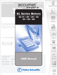
Thank you for selecting a Fisher Scientific accumet meter. This manual describes
the operation of the accumet XL50 meter. The state-of-the art meter that you have purchased runs on a Windows CE platform and has a similar framework of a pocket PC ( or
"Palm Pilot"). It is easy to operate and will guide you through the various functions by displaying easy to understand prompts. This operating manual should answer any questions
that might arise in operating your meter; however, do not hesitate to call our accumet
Technical Support Hotline at 1-888-358-4706, if you need any assistance.
This meter is designed to provide all the information necessary to guide you through the
measurement process with a series of prompts on the screen. The accumet XL50 provides
microprocessor precision in a compact benchtop design that is easy to use. One touch
screen controls all procedures, letting you:
• Measure pH or pH (FET); absolute mV or relative mV; ion concentration; and conductivity, resistivity, Total Dissolved Solids (TDS), or salinity
• Select one of three sets of standard pH buffer groups
Useful tips will appear
in this box throughout
this manual
• Standardize with up to five pH standard or custom buffers;
and with up to four conductivity standards
• Implement automatic pH buffer recognition or
automatic conductivity standard recognition
• Select one of six ion standardization methods
• Customize your display screen and operating parameters
• Assign operator and sample identification numbers
• Specify ion selective electrode type
• Store 1000 data points per user in the meter’s memory or transfer data to a computer or printer.
• Access extensive help with just a touch a button
It all adds up to rapid, completely automatic, intuitive operation.
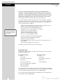
Unpacking the Meter
The following is a listing of what you should have received with your new accumet XL50
pH/mV/Ion/Conductivity meter.
Meter with kit includes
meter
Meter only includes
meter
power supply
power supply
electrode arm support bracket
electrode arm support bracket
electrode arm
electrode arm
pH electrode (13-620-130)
manual and literature
Two-cell conductivity probe (13-620-100)
ATC probe (13-620-19)
manual and literature
If any of these items are missing, please contact the accumet Technical Support Hotline at
1-888-358-4706. Accessory Conductivity Probes and Ion Selective Electrodes are available
and can be ordered by calling Fisher Customer Service at 800/766-7000.
Accessory pH, ISE, and Conductivity probes are available and can be ordered by calling
Fisher Customer Service at 800/766-7000.
4
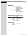
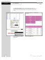
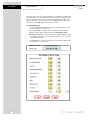
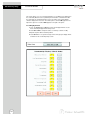
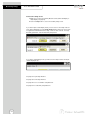
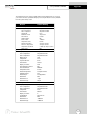
Specifications
Display
screen size
menu options
help screens
configurable display
keypad controls
640x480 digit LCD
4 1/2” x 6”
extensive
extensive
yes
context specific touchscreen
internal diagnostics
programmable data storage
programmable data output
print interval
programmable alarm
1000 data pts
yes
store on stable, time, manual
timed or logged data
3 to 86400 sec
yes
M e m o ry
pH Mode
range
resolution
relative accuracy
automatic buffer recognition
manual buffer recognition
calibration points
auto lock
FET
mV Mode
Ion Mode
range
resolution
accuracy
range
resolution
relative accuracy
calibration points
incremental methods
-2.000 to 20.000
0.1/0.01/0.001
± 0.1/0.01/0.002 + 1 Lsd
yes
yes
5
yes
yes
± 2000.0
0.1
± 0.2
1x10⁻⁶ to 9.99x10¹⁰
2 / 3 or 4 digits
±0.17n%
5
KA, KS, AA, AS
continued on next page
5
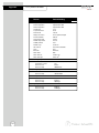
Specifications
Conductivity Mode
cell constants range
conductivity
resistivity
Total Dissolved Solids (TDS)
salinity
accuracy
Te m p e r a t u re Mode
General
range
resolution
accuracy
inputs/outputs
electrical requirements
output from PSU
line voltage tolerance
input impedance
meter size
meter weight
0.1, 1.0, 10
0 to 500 mS/cm over 4 ranges
0 to 200.0 µS, 200.0 µS to 2.000 mS,
2.000 to 20.00 mS, 20.00 to 500.0 mS
3 ohm-cm to 100 megohm-cm over 4 ranges
0 to 20.00 KOhms, 20.00 to 200.0 KOhms,
200.0 KOhms to 2.000 MOhms,
2.000 to 100.0 MOhms
0.0 to 500.0 ppt over 4 ranges
(depending on the TDS factor)
0 to 200.0 x TDS factor ppm,
200.0 x TDS factor to 2000 x TDS factor ppm,
2.000 x TDS factor to 20.00 x TDS factor ppt,
20.00 x TDS factor to 500.0 x TDS factor ppt
0 to 90 ppt over 4 ranges
0 to 0.094 ppt, 0.094 to 1.000 ppt,
1.000 to 11.50 ppt, 11.50 to 90.00 ppt
0.5% of full scale + 1 digit
-5.0 to +105.0 °C
0.1 °C
± 0.2 °C
BNC, Pin, ATC, DIN (for FET),
DIN (for conductivity)
115 V/60 Hz, 230 V/50 Hz
9VDC, 3.3A center negative
± 10%
>10 12 ohms
6.75"x9.25"x3.5"
2.8 lb.
Operating Conditions
operating temperature
operation humidity
maximum operating altitude
installation category
Pollution category degree
6
5-45 °C
5-80 % noncondensing
2000m
II
2
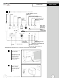
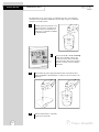
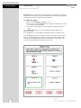
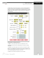
CONNECTORS
1
Getting Started
Review the layout and arrangement of the rear connector panel.
accuFET ISFET pH electrode
(Channel 3)
Stylus
Power
Automatic Temperature
Compensation (ATC) (Channel 1)
RJ 45
USB-B
Ver 1.1
USB-A,
Ver 1.1
twin port*
Reference pin jack (Channel 1)
BNC input connector
(Channel 1)
Audio output
(media player
applications)
Infrared
communication
Conductivity
Cell (Channel 5)
SD card reader
RS-232
BNC input connector
(Channel 2)
Reference pin jack (Channel 2)
Automatic Temperature
Compensation (ATC) (Channel 2)
*NOTE: USB devices like printer, mouse, etc. should be connected to the lower port (USB-A).
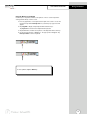
2
Connect the electrode
arm to the base.
Electrode base can be
attached to either side
of meter. Purchase
additonal arm with
base (13-637-671) to
use both sides.
3
Connect the power
cable to the rear
connector panel power
jack and to a power
source.
7
Getting Started
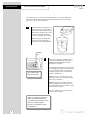
pH and ION SPECIFIC ELECTRODES
This meter allows you to use two types of pH electrodes: the conventional glass pH
electrode and the AccuFET field effect transistor (FET) pH electrode. This meter also
allows you to use ion specific electrodes.
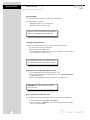
1
Carefully remove the protective cover
from the end of the electrode. Before
first using your glass pH electrode, or
whenever the electrode is dry, soak it
2-4 hours in an electrode storage
solution, pH 4 Buffer, or KCl solution.
Before using your ion specific electrode, consult the manufacturer’s
instructions for electrode preparation.
shorting
cap
2
Do not discard the
BNC shorting cap.
Remove the shorting cap on BNC connector.
Connect the combination pH electrode by
plugging it into the BNC input connector
(twisting to lock in place).
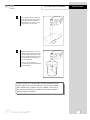
If a combination electrode isn’t used, connect
the indicating pH electrode into the BNC input
connector. Plug the reference electrode into
the reference pin jack. Also, install the ATC
probe into the ATC jack.
Note: Be sure to connect all probes to the
appropriate channel connectors (for example:
Input 1, Ref 1 and ATC1).
Option: Connect the optional AccuFET electrode by plugging it into the FET jack on the
back meter panel. Allow the AccuFET to warm
up five minutes before use.
Connect ion specific electrodes in the same
manner as pH electrodes.
If both a conventional electrode
and an AccuFET electrode are
connected to the meter, do not put
them in a solution together
because you will get inaccurate
measurements.
8
pH and ION SPECIFIC ELECTRODES
3
4
Getting Started
Rinse and blot-dry (don't wipe) electrodes between each measurement.
Rinse electrodes with distilled or
deionized water, or a portion of the
next solution to be measured.
Between measurements, store conventional pH electrodes in electrode
storage solution, pH 4 buffer, or KCl
solution. Refill when the level of solution gets below the manufacturer's
recommended level.
Store ion specific electrodes
according to electrode manufacturer’s
recommendations.
Proper electrode care is fundamental to obtaining reliable pH measurements. Improper care of the electrode may cause the meter reading to
drift, respond slowly, or produce erroneous readings. For this reason,
the electrode should always be conditioned and used in accordance
with manufacturer’s instructions.
9
Getting Started
CONDUCTIVITY CELLS
This meter allows you to use two types of conductivity cells: the 2-cell conductivity
cell and the 4-cell conductivity cell with DIN connector. Only one type of conductivity
cell can be connected at a time.
1
Carefully remove the protective cover
from the end of the conductivity cell.
Before using your conductivity cell,
soak it for 5 to 10 minutes in distilled
or deionized water.
2
3
4
10
Connect the 2-cell or 4-cell conductivity
cell to the conductivity cell jack. The
2-cell and 4-cell accumet conductivity
cells have built in ATC probes. Therefore,
there is no need to connect a separate
ATC probe.
Rinse and blot-dry (don't wipe) probe between each measurement. Rinse
probe with distilled or deionized water, or a portion of the next solution to be
measured.
Between measurements, conductivity
probes can be stored dry.
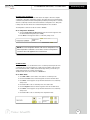
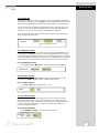
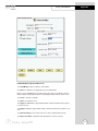
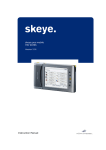
TOUCH SCREEN OPERATION
Using the Meter
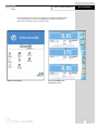
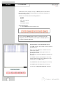
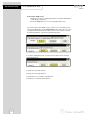
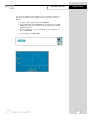
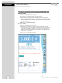
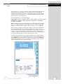
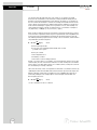
When the meter is turned on it first goes though self test, displays the FISHER Catalog
cover, briefly displays the desktop screen (Home) before loading the XL50 program
which results in the display of the measurement screen.
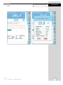
Desktop screen (Home)
pH, mV, and pH (FET) triple
measurement screen
11
Using the Meter
TOUCH SCREEN OPERATION
The new accumet XL50 benchtop meter operates with a state-of-the-art touch screen. The
touch screen makes this the easiest meter on the market to operate and care for. When
the meter is first plugged in, the meter runs a self-test and takes you to the measurement
screen. Touch any icon to access the functions of the meter. Your XL50 meter also
includes a stylus that you can use to tap on your screen. The stylus easily stores inside the
back panel of the meter.
The buttons on the right side of the screen control all of the functions of the meter. A light
touch on the screen is all that you need to access the various functions. Once you touch a
button you will get an audible tone; the screen will not change until you lift your stylus.
This design prevents rapid uncontrolled scrolling through the various function screens.
Function buttons and options change from screen to screen. Easy to understand prompts
guide you through the operation of the meter in the selected mode. If you are ever in doubt
about what to do, just touch Help on the bottom right corner of the screen for detailed
information about that screen.
Your meter was shipped with a clear protective sheet to protect the LCD display and “bubbles” may appear on the screen. The screen will respond better and visibility will improve if
it is removed. Alternatively, you may choose to leave this on for added protection.
NOTE: To turn off the display
without removing the power cord,
simply press the black button on
the back right of the meter.
Press again to turn display on.
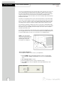
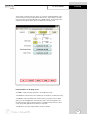
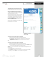
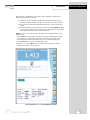
Screen contrast adjustment
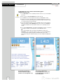
You can adjust the contrast of your screen to your requirements.
1. From the HOME screen, tap the bottom left of the screen to access the Start
menu. Tap Start > Settings > Control Panel. This launches the Control Panel
screen.
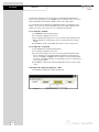
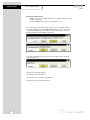
2. Tap the Display Contrast icon twice.
3. Use the up and down arrows to select your desired contrast.
4. Tap the Apply key to view your adjusted contrast. Tap the Close key to shut
the window.
12
Using the STYLUS
Using the Meter
Your XL50 Meter comes with a stylus that you should use to tap on your screen.
The stylus easily stores inside the back panel of the meter.
You can perform two basic actions using the stylus:
Tap
Lightly touch the screen to select or open an item. Lift the stylus after you tap an
item. Tapping is equivalent to clicking an item with the mouse on your personal
computer. Note: Some program items require a double tap to select or launch.
Double tap on the icons from the Desktop (Home) page and single click in the
XL50 application.
Drag
Place the point of the stylus on the screen and drag an item across the screen without lifting the stylus until you have completed the selection. Dragging is equivalent to
dragging with the left mouse button pressed on your personal computer .
Stylus Calibration
If your insturment is not responding properly to your taps, you may need to
recalibrate your screen.
1. From the HOME screen, tap the bottom left of the screen to access the Start
menu. Tap Start > Settings > Control Panel. This launches the Control
Panel screen.
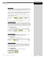
2. Tap the Stylus icon twice.
3. Tap the Calibration button to access the calibration screen.
4. Tap the Recalibrate button.
5. Carefully press and briefly hold the stylus on the center of the target.
Repeat as the target moves around the screen. If you miss the target center,
keep the stylus on the screen, slide it over the target’s center, and then lift
the stylus.
6. Once the calibration is complete, the target cursor will disappear.
Tap anywhere in the screen to go back to the “Stylus Properties” window.
Tap OK to close the “Stylus Properties” window.
CAUTION: To prevent damage to your XL50 screen, never use any
device other than the stylus that comes with the meter or an approved
replacement to tap on the screen. Order extra or replacements if you
lose or break your stylus.
13
Using the Meter
Setting TIME and DATE
Setting the Time
1. From the HOME screen tap the bottom left of the screen to access the Start
menu. Tap Start > Settings > Control Panel. This launches the Control
Panel screen.
2. Double tap Date/Time icon. This launches the Date/Time Properties
window.
3. Tap the time-zone down arrow, and select the appropriate time zone.
4. Tap the hour, minutes, or seconds. Use up and down arrows to adjust.
5. Tap AM or PM. Use up and down arrow to select.
6. Tap Apply button.
7. Tap OK to save the time.
Setting the Date
1. From the HOME screen tap the bottom left of the screen to access the Start
menu. Tap Start > Settings > Control Panel. This launches the Control
Panel screen.
2. Double tap Date/Time icon. This launches the Date/Time Properties
window.
3. Tap the left or right arrow to select a month and year.
4. Tap a day.
5. Tap Apply button.
6. Tap OK to save the time.
You need to reset your time zone, time, and date if:
• The time changes or you are traveling to a different time zone.
The time on the meter can be synchronized with your personal computer
through Microsoft® "Active sync".
14
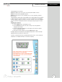
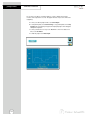
ON-SCREEN KEYBOARD
Using the Meter
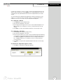
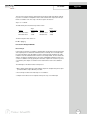
Using the On-Screen Keyboard
Use the stylus to tap letters, numbers, and symbols on the on-screen keyboard to
enter typed text directly onto the screen.
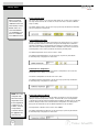
1. From any application, screen tap the bottom right of the screen to access the
input panel. Tap the Pencil/Keyboard icon (see below). A pop-up menu will
appear.
2. Tap LargeKB to display a large keyboard with all function keys.
Tap keyboard for a basic function alphanumeric keyboard.
3. Tap desired letters, numbers and symbols on the keyboard. Hit the enter key.
4. To remove keyboard, tap on Pencil icon. The pop-up menu will appear. Tap
Hide Input Panel to remove keyboard.
To see symbols, tap the Shift key.
15
Using the Meter
EXPANSION CARD
Expansion Cards
You can expand the memory and connectivity of your XL50 meter.
Use optional expansion cards for:
• Expanding the memory of your XL50 meter
• Viewing the content of memory cards
Expansion cards must be purchased separately
and are not included with your XL50 meter
Installing an Expansion Card
To install a Secure Digital (SD) card into an expansion slot on the XL50 meter:
1. Locate the slot on the top of XL50 meter.
2. Remove the protective plastic card.
3. Insert the expansion card into the expansion slot and push the connection edge of
the card firmly into the expansion slot.
If your expansion card is not recognized, follow
the card manufacturer’s instructions to install it.
Removing a Secure Digital (SD) Expansion Card
1. Close all applications that are using the expansion card.
2. Remove a card from the Secure Digital expansion slot by slightly pushing down
on the card to unlock it.
3. When the card disengages and pops up, pull it from the expansion slot.
CAUTION: SD cards must first be unlocked
before removal.
Viewing the Content of Memory Cards
Use File Explorer to view the files that are located on your optional Secure Digital card.
1. From the Start menu, tap Programs > File Explorer.
2. Tap the root directory of My Device, and select the Storage Card folder (SDIO) to
see a list of files and folders.
16
Connecting to the INTERNET
Using the Meter
Entering an Internet Address
With Pocket Internet Explorer and a connection to the Internet, you can view Web sites
on your XL50 meter by typing an address or Universal Resource Locator (URL) in the
Address bar. Web sites that use HTML 4.0, DHTML, animated GIF images, and Java
applets may not work correctly in Pocket Internet Explorer without additional software.
To enter an Internet address (URL) on your XL50 meter:
1. From the Start menu, tap Programs > Internet Explorer > Address Bar. If the
Address Bar is not visible, tap the View tab > Address Bar to turn it on. You may
also double tap the Internet Explorer icon on the Home screen to launch
Internet Explorer.
2. Enter the Internet address (URL) in the Address bar using the on-screen
keyboard.
3. Tap the Go icon.
Using a Favorites List
With Pocket Internet Explorer and a connection to the Internet, you can view Web sites
on your XL50 meter by selecting one from your Favorites list.
To select a Web site from your Favorites list:
1. From the Start menu, tap Internet Explorer.
2. Tap the Favorites icon and the Web site you want to view.
17
Using the Meter
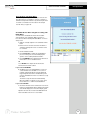
BUTTON FUNCTIONS
The touch screen of your XL50 bench meter has “buttons” along the right side of the
screen that are common to many of the screens. The following indicates the function of
these common buttons.
Channel 1
The Channel 1, Channel 2, Channel 3 and Channel 5 buttons access the
single display screen corresponding to each channel. If you wish to perform
standardization or printing from any of the channels, you need to use single
channel mode. The Graph can only be viewed in the single channel mode.
Channel 2
Channel 3
Channel 5
Mode
Setup
The Mode button allows you to switch between the various operations of the
meter—pH, mV, ion, pH (FET), conductivity, resistivity, TDS and salinity. It also
lets you configure the display options, select input parameters, and view the
software revision and serial number details.
The Setup button will access the setup screens of the measuring mode that
you are currently using.
The Log Data button sends data to the data storage center of the meter if a
sample ID# has been assigned to your sample.
Log Data
Profile
Home
Logoff
Help
18
The Profile button lets you view your
profile (User ID, Password, Company
Name, User Group) You can change only
your profile and not of any other user.
You can change to a different user only
if you are the default user of the system.
The Home button accesses the Windows CE desktop. The XL50 application
does not shut down if Home is pressed and the current user remains logged
in. Double tap on the XL50 icon to return to the previous screen before the
Home button was pressed.
The Logoff button allows you to logoff the current user from the XL50 application. The XL50 application shuts down returning to the Win CE desktop.
When you re-start the application, you go to the main screen of the application. The second time you are logged in as the default user of the system.
The Help button allows you to access helpful information on any screen.
Touching the Help button gives you information about the current screen.
This information will include step-by-step instructions for operating the meter
from the current screen and possible applications information for that screen.
BUTTON FUNCTIONS
Using the Meter
The following buttons appear in the Mode screen:
Replatinization is the process of replacing the platinum on the surfaces of
the 2 cell conductivity probes that may flake or wear off over time. The
platinum on the surface of the probe is used to increase the surface area
of the measuring surface resulting in decreased polarization error.
Replatinization is a relatively quick procedure to perform, taking no more
than 5 minutes. See Appendix page 132 for procedure.
The About button lets youview the software revision and serial number
details.
About
The Sys.Setup button allow you to turn on or off the beep status. This is
the audible beep that sounds each time any button is touched.
Sys. Setup
Multi Channel
Display Setup
The Multi Channel button lets you view multiple channels at the same
time. By default, the meter will display three channels: Ch1 in the upper
display (Display 1), Ch2 in the middle display (Display 2), and Ch5 in the
lower display (Display 3).
The Display Setup button lets you configure the display to read the
inputs from channels of your choice. The XL50 meter has four input
channels and offers a maximum of three simultaneous displays.
The following buttons appear in the mode screen after Ch1, 2, 3, or 5 is selected:
pH
The pH mode button allows you to switch to the various pH
operations of the meter (available in Channels 1 and 2).
mV
The mV mode button allows you to switch to the various mV
operations of the meter (available in Channels 1 and 2).
Ion
The Ion mode button allows you to switch to the various ion concentration operations of the meter (available in Channels 1 and 2).
pH (FET)
The pH (FET) mode button allows you to switch to the various pH
(FET) operations of the meter (available in Channel 3 only).
The Conductivity mode button allows you to switch to the various
conductivity operations of the meter. (available in Channel 5).
Conductivity
The Resistivity mode button allows you to switch to the various
resistivity operations of the meter. (available in Channel 5 ).
Resistivity
The TDS mode button allows you to switch to the various TDS
operations of the meter. (available in Channel 5).
TDS
The Salinity mode button allows you to switch to the various salinity
operations of the meter. (available in Channel 5).
Salinity
19
Using the Meter
BUTTON FUNCTIONS
The following buttons appear in all single channel screens:
Print
Standardize
Measure
The Print button will send information to the output device that
is connected to your meter. If you selected the “Log data” option in the
“Print criteria” setup, clicking on the print button will dump the logged
data to the printer.
The Standardize button accesses the standardization screen from the
various measure modes and initiates standardization of the meter once
the standardization screen is accessed.
The Measure button directs the meter to measure your sample when in
the Auto Read function of the pH, ion, or pH (FET) modes.
The following buttons appear in the mV single channel screen:
rel mV
abs mV
The rel mV button returns the meter into
the relative millivolt mode when in the
absolute mV mode. When this mode is
activated, a window will appear asking
you to set a relative mV value or accept
the default value of 0 mV. This feature
may assist the user to standardize
certain analytical and monitoring activities such as titration.
The abs mV button returns the meter to absolute millivolt mode when the
meter is in the relative mV mode. This button only appears when the
meter is in the relative mV mode
The following buttons appear in all standardization screens:
The Confirm button accepts current value of the buffer or standard
solution.
Confirm
The Clear button clears all previous standardization points.
Clear
The Cancel button cancels current standardization and returns to the
measurement screen..
Cancel
The Temp Std button allow you to check the accuracy of your
temperature probe and standardize to an accurate thermometer.
Temp Std
20
CHANNEL ASSIGNMENT
Using the Meter
The XL50 features four channels.
Channels 1 and 2 can be set for a pH or mV electrode with a BNC connector.
Channel 3 can be set for a pH (FET) electrode.
Channel 5 can be set for a 2-cell conductivity cell or a 4-cell conductivity cell with a
DIN connector.
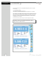
The XL50 features a triple, dual or single display mode. In triple display mode, the display
is split into thirds to show three channels of your choice simultaneously. In dual display
mode, the display is split into two halves to show two channels of your choice simultaneously. The parameters displayed are based on the Display Setup (see page 22 for directions).
Assigning the channels
1. Touch the Mode button on the Measure screen.
2. Touch a Channel button (Ch1, Ch2, Ch3, or Ch5) to select the parameter
assigned to that channel.
3. Touch the appropriate parameter icon to the right of the channel to assign an
input to each desired channel.
4. To deselect a channel, simply touch the the Channel button again.
If multiple channels are assigned, touch the Display Setup button to select and assign
displayed windows (see page 22 for directions).
To return to measurement mode, touch Multi Channel (if two, three, or four channels are
assigned) or touch Single Channel (if one channel is assigned).
21
Using the Meter
DISPLAY SETUP
Display Setup lets you select which channel will appear in each display. You can allocate
up to three of the four parameters to up to three displays. Access the Display Setup button
from the Mode screen when multiple channels are selected.
To configure the display:
1. Touch the desired Display box (Display 1, 2, or 3).
2. Touch any one of the three Channel boxes to the right of the display box to assign
the channel to the selected display.
3. To reassign any of the displays, touch the Display box again and the allocation
clears.
Touch the M. Channel button to save the configuration and return directly to the
Measurement screen.
Touch the OK button to save the display configuration and return to the Mode screen.
Touch the Cancel button to exit and return to the Mode screen without saving changes.
When you touch the Help button, information about the current screen appears. This
information includes step-by-step instructions for operating the meter from the current
screen and possible applications information for that screen.
22
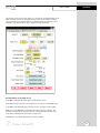
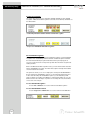
SETUP SCREEN
pH Setup
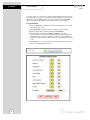
The pH Setup screen presents many options to control the pH operating parameters of the
meter. The meter is factory set with regard to these options, and is ready for use under
most circumstances (see appendix page 121 for default settings). The pH Setup section
will guide you through the various options available in the pH setup mode.
Function Buttons on pH Setup Screen
Touch OK to confirm pH Setup and return to the pH Measure screen.
Touch Cancel to exit and return to the pH Measure screen without confirming pH Setup.
Touch View to view all pH data points stored in memory. See pages 33-34 for details.
When you touch the Help button, information about the current screen appears. This
information includes step-by-step instructions for operating the meter from the current
screen and possible applications information for that screen.
Touch Reset to reset all pH Setup Criteria to the factory default.
23
pH Setup
pH SETUP SCREEN
To access the Setup screen:
1. Make sure you are in the pH Measure screen (either multiple display or single
display; see page 22).
2. Touch the Setup button to access the pH Setup screen.
If you were in triple or dual display mode, you have access to the Setup mode for
each channel displayed. Touch the Setup Channel buttons at the top of the screen
to toggle back and forth between the setup screens for each channel. To change pH
parameters, select the pH Setup button.
If you were in single display mode, you will access the Setup mode for the single
channel displayed only.
See page 23 for pH setup directions.
See page 35 for mV setup directions.
See page 44 for ion concentration setup directions.
See page 57 for conductivity setup directions.
24
Set SAMPLE ID#
pH Setup
A sample ID is required if you wish to log data or do a timed printing. Whenever this
option is active, each time you touch Log Data (available on the single display pH
Measure screen), the pH (or pH FET) value along with date/time/channel and the sample
ID will be sent to data storage.
You can manually enter an alphanumeric identification number of 10 characters for any
sample or you can have the meter sequentially number your samples beginning at the
number of your choice. You can also choose to deactivate the sample ID.
To set sample ID — Manual:
1. Touch Manual for manual Sample ID entry
2. The current ID is displayed on the screen
3. Use the alphanumeric keypad on the screen to enter the desired Sample ID. The
BS key will allow you to backspace to remove a character that was incorrectly
entered.
4. Touch Enter to accept current Sample ID and return to the pH (or pH FET) Setup
screen.
To set sample ID — Sequential
1. Touch Sequential for sequential Sample ID entry
2. The current ID is displayed on the screen
3. Use the numeric keypad on the screen to enter the desired Sample ID number
that you would like your sequential Sample ID assignment to begin with. Every
time you touch Print or Log Data on the pH Measure screen, the Sample ID will
increase by 1. The BS key will allow you to backspace to remove a character that
was incorrectly entered.
4. Touch Enter to accept the first sequential Sample ID and return to the pH (pH
FET) Setup screen.
To deactivate the sample ID assignment — None
1. Touch None to deactivate the sample ID assignment
25
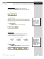
pH Setup
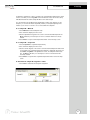
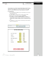
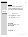
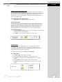
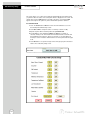
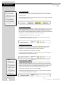
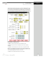
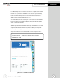
Select BUFFER GROUP
This setup option allows you to select from 3 different buffer groups, for auto buffer
recognition. Or you can create a custom group of buffers for auto buffer recognition by
touching custom.
The 3 existing buffer groups are :
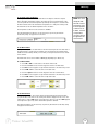
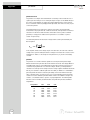
USA buffers:
2.00, 4.00, 7.00, 10.00, 12.00
European buffers: 1.00, 3.00, 6.00, 8.00, 10.00, 13.00
NIST buffers:
1.68, 4, 6.86, 9.18, 12.45
To select buffer group
1. Touch USA, EURO, NIST or CUSTOM from the setup screen to select a buffer
group.
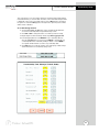
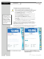
To set Custom pH buffer group
This option allows you to create a custom buffer group of up to 5 buffers (2 buffer minimum) to be used for auto buffer recognition. To obtain optimal results, it is important to
maintain at least 1 pH unit between selected buffers in the custom group.
1. Touch CUSTOM on the setup screen to select a custom buffer. This will display a
set of 5 custom beakers each initialized to zero.
2. Touch one of the beakers to display the numeric keypad.
3. Enter a value for the custom pH buffer that you want set in your custom buffer set.
4. Press Enter in the keypad to accept the value.
5. Repeat steps 2 through 4 until all 5 custom buffer beakers are populated with
desired values.
6. To modify the value entered, touch the particular beaker and key in the new value
using keypad.
7. To clear all custom buffer values, touch CLEAR.
26
Select BUFFER RECOGNITION / Select AUTO READ MODE
pH Setup
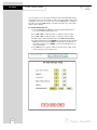
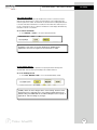
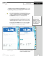
Select Buffer Recognition
This option allows you to select Automatic buffer recognition or manual buffer recognition when standardizing. With the automatic buffer recognition activated, the meter
will automatically recognize the buffers from the chosen buffer group and accept
them when the meter recognizes the reading as stable. When in the Manual buffer
recognition mode, you must enter the buffer value during the standardization procedure. The meter will accept the manually entered buffer when you recognize that the
measurement is stable. During the standardization procedure, you may accept the
buffer value before the meter recognizes it as stable by touching the
Standardization button.
To select Buffer Recognition
1. Touch MANUAL or AUTO to choose the method of buffer selection
Select Auto Read Mode
You can use this meter when the Auto Read function is active or when it is inactive.
When the Auto Read function is active, the meter will lock onto a reading when the
meter recognizes it as stable. The meter will not deviate from this reading until
Measure is touched. If the Auto Read function is inactive, then the meter will continuously monitor the pH of the sample and the Measure screen display will indicate
any fluctuation in the sample pH.
To select Auto Read Mode
1. Touch MANUAL or AUTO to choose the desired read mode.
27
pH Setup
Set pH STABILITY CRITERIA / Set DEFAULT TEMPERATURE
Set pH Stability Criteria
This setup screen allows you to determine how quickly the meter will respond to electrode
drift. There are three speed settings: fast, medium and slow
To set pH Stability Criteria
1. Touch FAST, MEDIUM, SLOW to choose the desired stability criteria.
Stability criteria are more stringent at the slower setting. Therefore, if the
highest precision is required, then a slow setting would be desired. The
default setting is the FAST and this should be adequate for the majority of
applications. without making any changes.
Set Default Temperature
It is a well known fact that pH is a temperature dependent measurement. The factory
default setting is 25°C. If you are measuring the pH of a solution that is not 25°C and you
are not using an Automatic Temperature Compensation (ATC) probe, then you should enter
the temperature value of that solution in order to get the correct pH value. The current
default temperature setting will be displayed on the screen.
The default temperature can be set from -5°C to 105°C.
To set Default Temperature
1. Select temperature units by touching the appropriate unit button: C (Celsius),
F (Fahrenheit) or K (Kelvin)
2. Touch the Default Temperature box and use the numeric keypad to enter the
desired default temperature (-5°C to 105°C).
3. Press Enter in the keypad to return to pH (pH FET) Setup screen
The use of an ATC probe provides a measured temperature value to
the meter and will override any value entered in the default temperature
screen. This measured value will be used by the meter to make pH
calculations.
28
Set ISOPOTENTIAL POINT / Set ALARM LIMITS
pH Setup
Set Isopotential Point
The isopotential point is the millivolt reading for an electrode at which temperature
has no effect on the measurement. pH electrodes are constructed so that the isopotential point is theoretically zero millivolts. This is very close to a pH of 7. Most pH
electrodes do not achieve this value precisely. However they are close enough so
that it is not usually necessary to use an isopotential point other than zero. The true
isopotential point of any given electrode must be determined experimentally.
(See Appendix: Determining Isopotential Points Experimentally, page 58)
The isopotential point can be set from -100 to +100
To set Isopotential Point
1. Touch the Isopotential Point box and use the numeric keypad to enter the
desired mV setting for the new isopotential point.
2. Touch Enter to accept this value and return to pH (pH FET) Setup screen.
Set Alarm Limits
This option allows you to set alarm limits for the pH measuring mode. If the pH value
of the measurement is outside of the boundaries set by the minimum and maximum
limits, audible and visual warnings will let you know that your sample measurement
was outside of the set limits.
The Alarm Limit can be set from -2 pH to 20 pH
To set Alarm Limits
1. Touch ON or OFF to set the status of the alarm of pH (pH FET) mode
2. Touch the Low box and use keypad to enter the new limit values.
3. Touch Enter on the keypad to accept this limit and return to the pH (pH FET)
Setup screen.
4. Touch the High box and use keypad to enter the new limit values.
5. Touch Enter on the keypad to accept this limit and return to the pH (pH FET)
Setup screen.
29
pH Setup
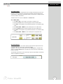
Set PRINT CRITERIA
This screen allows you to select which criteria are printed with the measurement when
you print the data. The status of the current print criteria is displayed on the screen. The
criteria option is active if ON appears to the right of the option. It is inactive if OFF
appears to the right of the option. Any active criteria will be printed on demand.
To set Print Criteria
1. Touch the Touch here to edit button next to the Print Criteria to access the pH
Print Criteria Setup screen.
2. Touch ON or OFF to change the status of a criteria you want to modify.
3. Repeat step 2 for all the remaining criteria except Print Option.
4. For Print Option select between Log Data and Timed. If “Log Data” is
selected, clicking on the “Print” button from the Measurement screen will send
the logged data to the printer. If “Timed” is selected, you can print data at an
interval you select. This data is buffered and is sent to the printer when the page
is full.
5. Touch OK button to accept the changes of the entire group of print criteria and
return to the pH (pH FET) Setup screen.
30
Set DATA STORAGE CRITERIA
pH Setup
This screen allows you to select which criteria are stored in the data logger with the
measurement when you store the data. The status of the current data storage criteria
is displayed on the screen. The criteria option is active if ON appears to the right of
the option. It is inactive if OFF appears to the right of the option. Any active criteria
will be stored on demand.
To set Data Storage Criteria
1. Touch the Touch here to edit button next to the Data Storage Criteria to
access the pH Data Storage Setup screen.
2. Touch ON or OFF to change the status of a criteria you want to modify.
3. Repeat step 1 for all the remaining criteria except Data storage Interval.
4. For Data storage Interval, touch MANUAL to log pH data only when the Log
Data button is pushed, touch STABLE to automatically log pH data when the
pH reading is stable, or touch TIMED to set a specific timed interval in seconds to log pH data.
5. Touch the OK button to accept the changes of the entire group of data
storage criteria and return to the pH (pH FET) Setup screen.
31
pH Setup
Set DISPLAY CRITERIA
This screen allows you to choose what information you would like to be displayed on
the pH Measure screen, particularly the information contained in the data box at the
bottom of the Measurement screen. The status of the current display criteria is displayed on the screen. The criteria option is active if ON appears to the right of the
option. It is inactive if OFF appears to the right of the option.
To set Display Criteria
1. Touch the Touch here to edit button next to the Display Criteria to access
the pH Display Criteria Setup screen.
2. Touch ON or OFF to change the status of a criteria you want to modify.
3. Repeat step 2 for all the remaining criteria except Display Resolution.
4. For Display Resolution, touch X.X to display pH with one decimal place,
touch X.XX to display pH with two decimal places, or touch X.XXX to display
pH with three decimal places.
3. Touch OK button to accept the changes of the entire group of display criteria
and return to the pH (pH FET) Setup screen.
32
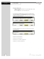
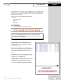
View STORED DATA
pH Setup
The XL50 has a memory capacity to store up to 1000 data points. The View Stored Data
screen allows you to look at specific data points stored in the meter based on the meters
memory capacity.
The meter stores pH or pH (FET) data under the following parameters:
Reading
Last Standardizations
Operator
Current Buffers
Date / Time / Channel
Slope
Sample Id
mV Measurement
Temperature
Meter Model Serial No.
To View Stored Data
1. Touch the View button in the pH Setup screen
You can only log 1000 data points at a time. To clear space for new
data points, you have to delete the same number of old data points as
you want to add new data points.
Function buttons on View Stored Data Screen
Touch OK to go back to the pH Setup screen from the View
Stored Data screen.
When you touch the Help button, information about the
current screen appears.
This information includes step-by-step instructions for
operating the meter from
the current screen and possible applications information for
that screen.
Touch Delete to delete a selected data point from the list.
To delete a data point, first touch the data point you want
to delete then touch the Delete button.
Touch Delete All to delete all the data point in the memory.
Touch Print to print all the data points in the memory.
See next page for Export View and Header explanation.
33
pH Setup
View STORED DATA
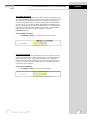
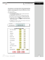
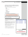
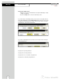
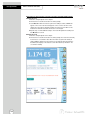
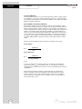
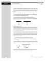
Touch Export View and Header to save your data in HTML format. The file can be
stored in either the Nand flash, SD Card or any of the other available locations as shown
in the window. After having selected the path, touch the alphanumeric keypad to name
your file.
Touch the alphanumeric keypad to
name your file.
34
Export view in HTML format
mV SETUP SCREEN
mV Setup
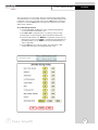
The mV Setup screen presents many options to control the operating parameters of the
meter. The meter is factory set with regard to these options, and is ready for use under
most circumstances (see appendix page 121 for default settings). The mV Setup section
will guide you through the various options available in the mV setup mode.
Function buttons on mV Setup Screen
Touch OK to confirm mV Setup and return to the mV Measure screen.
Touch Cancel to exit and return to the mV Measure screen without confirming mV Setup.
Touch View to view all mV data points stored in memory. See pages 42-43 for details.
When you touch the Help button, information about the current screen appears. This
information includes step-by-step instructions for operating the meter from the current
screen and possible applications information for that screen.
Touch Reset to reset all mV Setup Criteria to the factory default.
35
mV Setup
Access mV SETUP
To access the Setup screen:
1. Make sure you are in the mV Measure screen (either dual display or single
display; see page 22).
2. Touch the Setup button to access the mV Setup screen.
If you were in triple or dual display mode, you have access to the Setup mode for
each channel displayed. Touch the Setup Channel buttons at the top of the screen
to toggle back and forth between the setup screens for each channel. To change mV
parameters, select the mV Setup button.
If you were in single display mode, you will access the Setup mode for the single
channel displayed only.
See page 23 for pH setup directions.
See page 35 for mV setup directions.
See page 44 for ion concentration setup directions.
See page 57 for conductivity setup directions.
36
Set SAMPLE ID #
mV Setup
A sample ID is required if you wish to log data or do a timed printing. Whenever this option
is active, each time you touch Log Data on the mV Measure screen, the mV value along
with date/time/channel and the sample ID will be sent to data storage.
You can manually enter an alphanumeric identification number of 10 characters for any
sample or you can have the meter sequentially number your samples beginning at the
number of your choice. You can also choose to deactivate the sample ID.
To set sample ID — Manual:
1. Touch Manual for manual Sample ID entry.
2. The current ID is displayed on the screen.
3. Use the alphanumeric keypad on the screen to enter the desired Sample ID. The
BS key will allow you to backspace to remove a character that was incorrectly
entered.
4. Touch Enter to accept current Sample ID and return to the mV Setup screen.
To set sample ID — Sequential
1. Touch Sequential for sequential Sample ID entry
2. The current ID is displayed on the screen
3. Use the numeric keypad on the screen to enter the desired Sample ID number that
you would like your sequential Sample ID assignment to begin with. Every time you
touch Print or Log Data on the pH Measure screen, the Sample ID will increase
by 1. The BS key will allow you to backspace to remove a character that was
incorrectly entered.
4. Touch Enter to accept the first sequential Sample ID and return to the mV Setup
screen.
To deactivate the sample ID assignment — None
1. Touch None to deactivate the sample ID assignment
37
mV Setup
Set ALARM LIMITS
This option allows you to set alarm limits for the mV measuring mode. If the mV
value of the measurement is outside of the boundaries set by the minimum and
maximum limits, audible and visual warnings will let you know that your sample
measurement was outside of the set limits.
The Alarm Limit can be set from -2000.0 mV to 2000.0 mV
To set Alarm Limits
1. Touch ON or OFF to set the status of the alarm of mV mode
2. Touch the Low box and use keypad to enter the new limit values.
3. Touch Enter on the keypad to accept this limit and return to the pH mV
Setup screen.
4. Touch the High box and use keypad to enter the new limit values.
5. Touch Enter on the keypad to accept this limit and return to the mV Setup
screen.
38
Set PRINT CRITERIA
mV Setup
This screen allows you to select which criteria are printed with the measurement when
you print the data. The status of the current print criteria is displayed on the screen. The
criteria option is active if ON appears to the right of the option. It is inactive if OFF
appears to the right of the option. Any active criteria will be printed on demand.
To set Print Criteria
1. Touch the Touch here to edit button next to the Print Criteria to access the mV
Print Criteria Setup screen.
2. Touch ON or OFF to change the status of a criteria you want to modify.
3. Repeat step 2 for all the remaining criteria except Print Option.
4. For Print Option, select between Log Data and Timed. If “Log Data” is
selected, clicking on the “Print” button from the Measurement screen will send
the logged data to the printer. If “Timed” is selected, you can print data at an
interval you select. This data is buffered and is sent to the printer when the page
is full.
5. Touch OK button to accept the changes of the entire group of print criteria and
return to the mV Setup screen.
39
mV Setup
Set DATA STORAGE CRITERIA
This screen allows you to select which criteria are stored in the data logger with the
measurement when you store the data .The status of the current data storage criteria
is displayed on the screen. The criteria option is active if ON appears to the right of
the option. It is inactive if OFF appears to the right of the option. Any active criteria
will be stored on demand.
To set Data Storage Criteria
1. Touch the Touch here to edit button next to the Data Storage Criteria to
access the mV Data Storage Setup screen.
2. Touch ON or OFF to change the status of a criteria you want to modify.
2. Touch ON or OFF to change the status of a criteria you want to modify.
3. Repeat step 2 for all the remaining criteria except Data storage Interval.
4. For Data storage Interval, touch MANUAL to log mV data only when the Log
Data button is pushed, touch STABLE to automatically log mV data when
mV reading is stable, or touch TIMED to set a specific timed interval in seconds to log mV data.
5. Touch OK button to accept the changes of the entire group of data storage
criteria and return to the mV Setup screen.
40
Set DISPLAY CRITERIA
mV Setup
This screen allows you to choose what information you would like to be displayed on
the mV Measure screen, particularly the information contained in the data box at the
bottom of the Measurement screen. The status of the current display criteria is displayed on the screen. The criteria option is active if ON appears to the right of the
option. It is inactive if OFF appears to the right of the option.
To set Display Criteria
1. Touch the Touch here to edit button next to the Display Criteria to access
the mV Display Criteria Setup screen.
2. Touch ON or OFF to change the status of a criteria you want to modify.
3. Repeat step 2 for all the remaining criteria except Display Resolution.
4. For Display Resolution, touch X to set display with 1 mV resolution or touch
X.X to set display with 0.1 mV resolution.
3. Touch OK button to accept the changes of the entire group of display criteria
and return to the mV Setup screen.
41
mV Setup
View STORED DATA
The XL50 has a memory capacity to store up to 1000 data points. The View Stored
Data screen allows you to look at specific data points stored in the meter based on
the meters memory capacity.
The meter stores mV data under the following parameters:
Reading
Operator
Date / Time / Channel
Sample Id
Meter Model Serial No.
To View Stored Data
1. Touch the View button in the mV Setup screen
You can only log 1000 data points at a time. To clear space for new
data points, you have to delete the same number of old data points as
you want to add new data points.
Function buttons on View Stored Data Screen
Touch OK to go back to the pH Setup screen from the View
Stored Data screen.
When you touch the Help button, information about the
current screen appears.
This information includes step-by-step instructions for
operating the meter from
the current screen and possible applications information for
that screen.
Touch Delete to delete a selected data point from the list.
To delete a data point, first touch the data point you want
to delete then touch the Delete button.
Touch Delete All to delete all the data point in the memory.
Touch Print to print all the data points in the memory.
See next page for Export View and Header explanation.
42
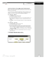
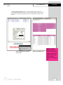
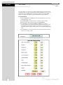
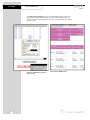
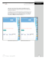
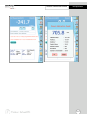
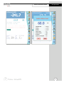
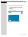
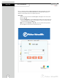
View STORED DATA
mV Setup
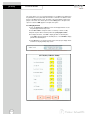
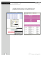
Touch Export View and Header to save your data in HTML format. The file can be
stored in either the Nand flash, SD Card or any of the other available locations as shown
in the window. After having selected the path, touch the alphanumeric keypad to name
your file.
Touch the alphanumeric keypad to
name your file.
Export view in HTML format
raghu, I missed
updating the pH
screen, but the mV
image above is the
newest one I have.
Do you have a
newer one to send
me?
43
Ion Setup
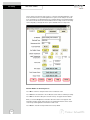
ION SETUP SCREEN
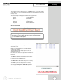
The Ion Setup screen presents many options to control the operating parameters of the
meter. The meter is factory set with regard to these options, and is ready for use under
most circumstances (see appendix page 121 for default settings). The operating parameters of the Ion mode can be set and controlled from the Ion setup screen. The Ion Setup
section will guide you through the various options available in the Ion setup mode.
Function Buttons on Ion Setup Screen
Touch OK to confirm Ion Setup and return to the Ion Measure screen.
Touch Cancel to exit and return to the Ion Measure screen without confirming Ion Setup.
Touch View to view all Ion data points stored in memory. See pages 55-56 for details.
When you touch the Help button, information about the current screen appears. This
information includes step-by-step instructions for operating the meter from the current
screen and possible applications information for that screen.
Touch Reset to reset all Ion Setup Criteria to the factory default.
44
Access ION SETUP
Ion Setup
To access the Setup screen:
1. Make sure you are in the Ion Measure screen (either dual display or single
display; see page 22).
2. Touch the Setup button to access the Ion Setup screen.
If you were in triple or dual display mode, you have access to the Setup mode for
each channel displayed. Touch the Setup Channel buttons at the top of the screen
to toggle back and forth between the setup screens for each channel. To change ion
parameters, select the ion Setup button.
If you were in single display mode, you will access the Setup mode for the single
channel displayed only.
See page 23 for pH setup directions.
See page 35 for mV setup directions.
See page 44 for ion concentration setup directions.
See page 57 for conductivity setup directions.
45
Ion Setup
SAMPLE ID
A sample ID is required if you wish to log data or do a timed printing. Whenever this
option is active, each time you touch Log Data on the Ion Measure screen, the Ion value
along with date/time/channel and the sample ID will be sent to data storage.
You can manually enter an alphanumeric identification number of 10 characters for any
sample or you can have the meter sequentially number your samples beginning at the
number of your choice. You can also choose to deactivate the sample ID.
To set sample ID — Manual:
1. Touch Manual for manual Sample ID entry
2. The current ID is displayed on the screen
3. Use the alphanumeric keypad on the screen to enter the desired Sample ID. The
BS key will allow you to backspace to remove a character that was incorrectly
entered.
4. Touch Enter to accept current Sample ID and return to the Ion Setup screen.
To set sample ID — Sequential
1. Touch Sequence for sequential Sample ID entry
2. The current ID is displayed on the screen
3. Use the numeric keypad on the screen to enter the desired Sample ID number
that you would like your sequential Sample ID assignment to begin with. Every
time you touch Print or Log Data on the Ion Measure screen, the Sample ID will
increase by 1. The BS key will allow you to backspace to remove a character that
was incorrectly entered.
4. Touch Enter to accept the first sequential Sample ID and return to the Ion Setup
screen.
To deactivate the sample ID assignment — None
1. Touch None to deactivate the sample ID assignment
46
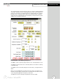
ION METHOD
Ion Setup
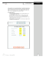
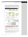
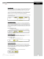
The Ion Method window lets you select from a variety of ion measurement methods.
Direct Reading with Standards: The most common method of ion measurement. When
using this method, you will use standards of known values to standardize the meter with
ion standards. An ionic strength adjuster (ISA) is added to both the standards and the
sample. Two to five standards are used. The standards should bracket the expected value
of the sample. The ion specific electrode is immersed in a stirring sample and the ion
concentration is read directly from the meter.
Direct Reading with Blank Offset: Commonly used for determining ion concentration
in a sample with a very low level of ions. Due to background interference at low
concentration levels, a blank is used and the value of the ion concentration in the blank
is subtracted from the value of the measured sample.
Known Addition Method: An incremental method used for samples with a complex
matrix. A standard with a known concentration of the ion species of interest is added to
the sample. The difference in mV potential is then used to calculate ion concentration.
Known Subtraction Method: An incremental method where the ion of interest in the
sample is not identical to the ion in the standard solution. The standard of known ion
concentration that is added to the sample quantitatively reacts in the sample with the ion
of interest. This reaction removes a fixed amount of the ion of interest from the sample
solutions. The ion concentration is then calculated based upon the difference in the mV
potential.
Analate Addition: A modification of the known addition method. The initial mV
measurement is recorded in a standard solution. The ion in the standard solution is the ion
of interest and is detected by the ion selective electrode in use. A sample containing the
ion of interest is then added to the standard solution. The difference in the mV potential
is then used in the calculation of the concentration of the ion of interest. This method is
useful if the sample temperature is significantly different than that of the standard. When
the small volume of hot sample is added to the larger volume, the temperature impact
becomes negligible.
Analate Subtraction: Useful when there is no ion specific electrode available to directly
measure the concentration of the ion of interest. This method employs the addition of a
sample of the ion of interest to a standard containing a different ion of known concentration. The ion of interest will quantitatively react with the ion in the standard, creating a
complex and removing the ion from the standard solution. The ion specific electrode is
specific for the ion in the standard solution and not for the ion of interest. The difference in
mV potential is used to calculate the concentration of the ion of interest based upon this
quantitative reaction.
To select Ion Method:
1. Touch the Arrow key to the right of Ion Method
2. Touch the desired method.
47
Ion Setup
ELECTRODE TYPE / MEASUREMENT UNITS
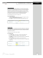
Select Electrode Type
This screen lets you select the type of electrode that is specific for your ion of interest.
Your choice of electrode informs the meter which default slope to use in the calculations
made for electrode efficiency and sample concentration. Once you have selected an
electrode, you will not be required to enter the default slope numerically.
Note: the default slope value specific for the electrode that you choose is a theoretical
slope value that is used in the calucaltions to determine the efficiency of your electrode.
This slope value is not the slope value that is displayed in the data box of the measurement screen. You will still need to standardize the meter using ion standards to determine
the actual efficiency of your electrode.
Changing electrode type
will erase the previous
standardization.
To select electrode type:
1. Touch the Electrode Type box to view the list of electrodes.
2. Use the scroll bar to select the desired electrode type.
If you are using several different electrodes, you can create a
different User Profile for each electrode to save individual
parameters and calibration information (i.e. “Ammonia
Samples” or “Sodium Batch Testing”. See pages 95-97 for
directions on how to set up a user profile.
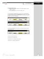
Select Measurement Units
This screen lets you select the units in which the meter will report the concentration of
the ion of interest. The current units are displayed on the screen.
To select measurement units:
1. Touch the Measurement Unit box to view the list of measurement units.
2. Use the scroll bar to select the desired units.
Once the unit has been calibrated with a particular unit of measurement, if an attempt is
made to change the units, the unit comes out with a warning message: “Changing the
measurement unit will erase previous standardization. Do you wish to continue?”
48
AUTO READ MODE / ION STABILITY CRITERIA
Ion Setup
Select Auto Read Mode
You can use this meter when the Auto Read function is active or when it is inactive.
When the Auto Read function is active, the meter will lock onto a reading when the
meter recognizes it as stable. The meter will not deviate from this reading until Measure
is touched. If the Auto Read function is inactive, then the meter will continuously monitor the concentration of the ion of interest. The Measure screen display will indicate any
fluctuation in the ion concentration.
To select Auto Read Mode
1. Touch MANUAL or AUTO to choose the desired read mode.
Regardless of the status of the Auto Read Mode, STABLE will be
displayed as the meter recognizes the measurement as stable.
Set Ion Stability Criteria
This setup screen allows you to determine how quickly the meter will respond to
electrode drift. There are three speed settings: fast, medium and slow
To set Ion Stability Criteria
1. Touch FAST, MEDIUM, SLOW to choose the desired stability criteria.
Stability criteria are more stringent at the slower setting. Therefore, if the
highest precision is required, then a slow setting would be desired. The
default setting is the FAST and this should be adequate for the majority of
applications. without making any changes.
49
Ion Setup
DEFAULT TEMPERATURE
Set Default Temperature
It is a well known fact that ion concentration is a temperature dependent measurement. The factory default setting is 25°C. If you are measuring a solution that is not
25°C and if you are not using a temperature probe, then you should enter the temperature value of that solution in order to get the correct concentration value. The
current default temperature setting will be displayed on the screen.
The default temperature can be set from -5°C to 105°C.
To set Default Temperature
1. Select temperature units by touching the appropriate unit button: C (Celsius),
F (Fahrenheit) or K (Kelvin).
2. Touch the Default Temperature box and use the numeric keypad to enter
the desired default temperature (-5°C to 105°C).
3. Press Enter in the keypad to return to Ion Setup screen.
Best results are obtained when the standards and the samples are at the
same temperature.
50
TEMPERATURE COMPENSATION / ISOPOTENIAL POINT / ALARM LIMITS
Ion Setup
Set Apply Temperature Compensation
Ion concentration is a temperature dependent measurement. Best results are obtained
when the standards and the samples are standardized and calibrated at the same temperature. However, if you have experimentally determined the isopotential point of your
electrode then you can choose to set ATC to YES and enter the isopotential value. This
option is set to NO by default.
To set Apply Temperature Compensation
1. Touch YES to choose Apply Temperature Compensation.
Set Isopotential Point
The isopotential point is the millivolt reading for an electrode at which temperature has
no effect on the measurement. Ion Selective Electrodes, unlike pH electrodes, are not
designed to achieve any particular isopotential point. If samples and standards are at
different temperatures when performing ISE experiments, it will be necessary to e
xperimentally determine the isopotential point of your own Ion Specific Electrode.
To set Isopotential Point
1. Touch the Isopotential Point box and use the numeric keypad to enter the desired
mV setting for the new isopotential point.
2. Touch Enter to accept this value and return to Ion Setup screen.
Set Alarm Limits
This option allows you to set alarm limits for the ion measuring mode. If the ion
concentration value of the measurement is outside of the boundaries set by the
minimum and maximum limits, a visual warning will appear to let you know that your
sample measurement was outside of the set limits.
The validity range of alarm limits is 0.000001 to 99,900,000,000.
To set Alarm Limits
1. Touch ON or OFF to set the status of the alarm.
2. Touch the Low box and use keypad to enter the new limit values.
3. Touch Enter on the keypad to accept this limit and return to the Ion Setup
screen.
4. Touch the High box and use keypad to enter the new limit values.
5. Touch Enter on the keypad to accept this limit and return to the Ion Setup
screen.
51
Ion Setup
PRINT CRITERIA
This screen allows you to select which criteria are printed with the measurement when
you print the data. The status of the current print criteria is displayed on the screen. The
criteria option is active if ON appears to the right of the option. It is inactive if OFF
appears to the right of the option. Any active criteria will be printed on demand.
To set Print Criteria
1. Touch the Touch here to edit button next to the Print Criteria to access the Ion
Print Criteria Setup screen.
2. Touch ON or OFF to change the status of a criteria you want to modify.
3. Repeat step 2 for all the remaining criteria except Print Option.
4. For Print Option, select between Log Data and Timed. If “Log Data” is
selected, clicking on the “Print” button from the Measurement screen will send
the logged data to the printer. If “Timed” is selected, you can print data at an
interval you select. This data is buffered and is sent to the printer when the page
is full.
5. Touch OK button to accept the changes of the entire group of print criteria and
return to the Ion Setup screen.
52
DATA STORAGE CRITERIA
Ion Setup
This screen allows you to select which criteria are stored in the data logger with the
measurement when you store the data .The status of the current data storage criteria
is displayed on the screen. The criteria option is active if ON appears to the right of
the option. It is inactive if OFF appears to the right of the option. Any active criteria
will be stored on demand.
To set Data Storage Criteria
1. Touch the Touch here to edit button next to the Data Storage Criteria to
access the pH Data Storage Setup screen.
2. Touch ON or OFF to change the status of a criteria you want to modify.
3. Repeat step 2 for all the remaining criteria except Data storage Interval.
4. For Data storage Interval, touch MANUAL to store Ion data only when the
Log Data button is pushed, touch STABLE to automatically store Ion data
when Ion reading is stable, or touch TIMED to set a specific timed interval in
seconds to store Ion data.
5. Touch OK button to accept the changes of the entire group of data storage
criteria and return to the Ion Setup screen.
53
Ion Setup
DISPLAY CRITERIA
This screen allows you to choose what information you would like to be displayed on
the Ion Measure screen, particularly the information contained in the data box at the
bottom of the Measurement screen. The status of the current display criteria is displayed on the screen. The criteria option is active if ON appears to the right of the
option. It is inactive if OFF appears to the right of the option.
To set Display Criteria
1. Touch the Touch here to edit button next to the Display Criteria to access
the pH Display Criteria Setup screen.
2. Touch ON or OFF to change the status of a criteria you want to modify.
3. Repeat step 2 for all the remaining criteria except Display Resolution.
4. Display Resolution lets you select the number of significant figures that will
be used when reporting your ion measurement. Touch 2, 3, or 4 to select the
desired significant digits.
5. Touch OK button to accept the changes of the entire group of display criteria
and return to the Ion Setup screen.
54
VIEW STORED DATA
Ion Setup
The XL50 has a memory capacity to store up to 1000 data points. The View Stored Data
screen allows you to sort and look at specific data points stored in the meter based on
the meters memory capacity. The stored data can be sorted by any of the parameters
available in the screen header.
The meter stores Ion data under the following parameters:
Reading
Date / Time / Channel
Sample Id
Temperature
mV measurement
To View Stored Data
1. Touch the View button in the mV Setup screen
You can only log 1000 data points at a time. To clear space for new
data points, you have to delete the same number of old data points as
you want to add new data points.
Function buttons on View Stored Data Screen
Touch OK to go back to the Ion Setup screen from the
View Stored Data screen.
When you touch the Help button, information about the
current screen appears. This information includes step-bystep instructions for operating the meter from the current
screen and possible applications information for that
screen.
Touch Delete to delete a selected data point from the list.
To delete a data point, first touch the data point you want
to delete then touch the Delete button.
Touch Delete All to delete all the data point in the memory.
Touch Print to print all the data points in the memory.
See next page for Export View and Header explanation.
55
Ion Setup
VIEW STORED DATA
Touch Export View and Header to save your data in HTML format. The file can be
stored in either the Nand flash, SD Card or any of the other available locations as
shown in the window. After having selected the path, touch the alphanumeric keypad
to name your file.
Touch the alphanumeric keypad to
name your file.
56
Export view in HTML format
CONDUCTIVITY SETUP SCREEN
Conductivity Setup
The conductivity Setup screen present many options to control the operating parameters
of the meter. The meter is factory set with regard to these options, and is ready for use
under most circumstances (see appendix page 122 for default settings). The operating
parameters of the conductivity mode can be set and controlled from the conductivity
setup screen. The conductivity Setup section will guide you through the various options
available in the conductivity setup mode.
Function Buttons on Conductivity Setup Screen
Touch OK to confirm conductivity Setup and return to the conductivity Measure screen.
Touch Cancel to exit and return to the conductivity Measure screen without confirming
conductivity Setup.
Touch View to view all conductivity data points stored in memory. See pages 67-68 for
details.
When you touch the Help button, information about the current screen appears. This
information includes step-by-step instructions for operating the meter from the current
screen and possible applications information for that screen.
Touch Reset to reset all conductivity Setup Criteria to the factory default.
57
Conductivity Setup
Access CONDUCTIVITY SETUP
To access the Setup screen:
1. Make sure you are in the conductivity Measure screen (either dual display or
single display; see page 22).
2. Touch the Setup button to access the conductivity Setup screen.
If you were in triple or dual display mode, you have access to the Setup mode for
each channel displayed. Touch the Setup Channel buttons at the top of the screen
to toggle back and forth between the setup screens for each channel. To change
Conductivity parameters, select the Conductivity Setup button.
If you were in single display mode, you will access the Setup mode for the single
channel displayed only.
See page 23 for pH setup directions.
See page 34 for mV setup directions.
See page 44 for ion concentration setup directions.
See page 57 for conductivity setup directions.
58
Set SAMPLE ID #
Conductivity Setup
A sample ID is required if you wish to log data or activate a timed printing. Whenever this
option is active, each time you touch Log Data on the conductivity Measure screen, the
conductivity value along with date/time/channel and the sample ID will be sent to data
storage.
You can manually enter an alphanumeric identification number of 10 characters for any
sample or you can have the meter sequentially number your samples beginning at the
number of your choice. You can also choose to deactivate the sample ID.
To set sample ID — Manual:
1. Touch Manual for manual Sample ID entry.
2. The current ID is displayed on the screen.
3. Use the alphanumeric keypad on the screen to enter the desired Sample ID. The
BS key will allow you to backspace to remove a character that was incorrectly
entered.
4. Touch Enter to accept current Sample ID and return to the mV Setup screen.
To set sample ID — Sequential
1. Touch Sequence for sequential Sample ID entry
2. The current ID is displayed on the screen
3. Use the numeric keypad on the screen to enter the desired Sample ID number that
you would like your sequential Sample ID assignment to begin with. Every time you
touch Print or Log Data on the pH Measure screen, the Sample ID will increase
by 1. The BS key will allow you to backspace to remove a character that was
incorrectly entered.
4. Touch Enter to accept the first sequential Sample ID and return to the mV Setup
screen.
To deactivate the sample ID assignment — None
1. Touch None to deactivate the sample ID assignment
59
Conductivity Setup
CONDUCTIVITY STANDARDS/Select STANDARD RECOGNITION
Conductivity Standards
This setup option shows the set conductivity standards available for auto standard
recognition. If Manual standard recognition is selected, the Conductivity Standards section will be blank.
Conductivity Standards available with Auto Standard Recognition
Setup Screen with Manual Standard Recognition
Select Standard Recognition
This option allows you to select Automatic standard recognition or manual standard
recognition when standardizing. With the automatic standard recognition activated,
the meter will automatically recognize the buffers from the preset group (84 uS,
1.413 mS, 12.88 mS and 111.8 mS) and accept them when the meter recognizes the
reading as stable.
When in the Manual standard recognition mode, you must enter the buffer value during the standardization procedure. The meter will accept the manually entered buffer
once the measurement is stable.
This option also allows you to choose single-point or multi-point standardardization.
Use the single-point standardization option if you are measuring samples that close
in value. Use the multi-point standardization option if you are measuring a wide
range of samples. If a single point calibration is selected, there will be only one calibration factor for the entire range of operation. In the multi point mode, there will be
one for each of the 4 ranges.
To select Standard Recognition
1. Touch Auto or Manual to choose the method of standard recognition.
To select Standardization Points
1. Touch Single Point or Multi Point to choose the method of standardization.
60
Select STABLE indicator / AUTO READ MODE / CELL CONSTANT
Conductivity Setup
Select Stable Indicator
This setup option lets you turn ON or OFF the stability indicator. When this
function is turned on, the STABLE appears when the conductivity reading is stable.
To select Stable indicator
1. Touch ON or OFF to turn stable indicator on or off.
Select Auto Read Mode
You can use this meter when the Auto Read function is active or when it is inactive.
When the Auto Read function is active, the meter will lock onto a reading when the
meter recognizes it as stable. The meter will not deviate from this reading until Measure
is touched. If the Auto Read function is inactive, then the meter will continuously
monitor any resistivity fluctuations.
To select Auto Read Mode
1. Touch MANUAL or AUTO to choose the desired read mode.
Regardless of the
status of the Auto
Read Mode, STABLE
will be displayed as
the meter recognizes
the measurement as
stable.
Select Cell Constant
This setup option allows you to select the appropriate cell constant of the
conductivity cell that you are using. There are three cell constants to choose
from. Each is used for a different range of conductivity. The following indicates
the optimal conductivity range for the accumet conductivity cells.
Cell Constant
Optimal Conductivity Range
2-cell
4-cell
0.1
1.0
10.0
0.5 to 200 µS/cm
0.01 to 2 mS/cm
1 to 200 mS/cm
Not Available
0.01 to 20 mS/cm
1 to 200 mS/cm
Check the part number on your accumet® conductivity cell and compare to chart on
the previous page to determine the cell constant of your conductivity cell.
To select Cell Constant
1. Touch 0.100/cm, 1.000/cm, or 10.00/cm to choose the correct cell constant.
When you change
cell constants your
calibration factor will
automatically reset to
default values. It is
recommended that you
standardize your meter
to establish a new
calibration factor.
61
Conductivity Setup
Set DEFAULT TEMPERATURE / Set REFERENCE TEMPERATURE
Set Default Temperature
Conductivity is a temperature dependent measurement. This option allows you to
select a default temperature that the meter will use along with the temperature coefficient to calculate a temperature corrected conductivity measurement.
accumet® conductivity
cells for the XL50 have
a built-in Temperature
sensor.
If an ATC probe is used any value entered as a default temperature will be overridden in favor of the actual measured temperature of the solution provided to the
meter by the ATC probe.
The default temperature can be set from -10°C to 110°C.
To set Default Temperature
1. Select temperature units by touching the appropriate unit button: C (Celsius),
F (Fahrenheit) or K (Kelvin).
2. Touch the Default Temperature box and use the numeric keypad to enter
the desired default temperature (-10°C to 110°C).
3. Press Enter in the keypad to return to conductivity Setup screen.
Set Reference Temperature
This setup option allows you to select the reference temperature to be used in the
determination of the conductivity of your sample. The reference temperature is the
temperature to which the conductivity readings would be normalized.
The reference temperature can be set from 15°C to 30°C.
To set Reference Temperature
1. Select temperature units by touching the appropriate unit button: C (Celsius),
F (Fahrenheit) or K (Kelvin).
2. Touch the Reference Temperature box and use the numeric keypad to enter
the desired default temperature (15°C to 30°C).
3. Press Enter in the keypad to return to conductivity Setup screen.
Note: The units of all temperature parameters must match.
The meter will automatically modify the temperature units of
Default Temperature and Reference Temperature to match
the last choice made on any of these parameters.
62
Set TEMPERATURE COEFFICIENT / Set ALARM LIMITS
Conductivity Setup
Set Temperature Coefficient
The temperature coefficient is a value that reflects the degree to which the sample’s
conductivity is effected by temperature changes. The meter will use the set temperature
coefficient along with the measured temperature provided by the ATC probe to calculate
what the conductivity would be at the selected reference temperature. If no ATC probe
is being used, the meter will use the set default temperature in the calculation.
The temperature coefficient can be set from 0 to 10.000%.
To set Temperature Coefficient
1. Touch the Temperature Coefficient box and use the numeric keypad to enter
the desired default temperature (0 to 10.000).
3. Press Enter in the keypad to return to conductivity Setup screen.
NOTE: The meter and probe with ATC will measure temperature even
if the temperature coefficient is set to 0.0%, however a temperature
correction will not be applied to the measurement.
Set Alarm Limits
This option allows you to set alarm limits for the conductivity measuring mode. If the
conductivity value of the measurement is outside of the boundaries set by the minimum and maximum limits, audible and visual warnings will let you know that your
sample measurement was outside of the set limits.
The Alarm Limit can be set from 0.0 uS to 500000.00 uS.
To set Alarm Limits
1. Touch ON or OFF to set the status of the alarm of conductivity mode
2. Touch the Low box and use numeric keypad to enter the new limit values.
3. Touch Enter on the keypad to accept this limit and return to the conductivity
Setup screen.
4. Touch uS or mS to select conductivity units of low alarm value.
5. Touch the High box and use numeric keypad to enter the new limit values.
6. Touch Enter on the keypad to accept this limit and return to the conductivity
Setup screen.
7. Touch uS or mS to select conductivity units of high alarm value.
63
Conductivity Setup
Set PRINT CRITERIA
This screen allows you to select which criteria are printed with the measurement when
you print the data. The status of the current print criteria is displayed on the screen. The
criteria option is active if ON appears to the right of the option. It is inactive if OFF
appears to the right of the option. Any active criteria will be printed on demand.
To set Print Criteria
1. Touch the Touch here to edit button next to the Print Criteria to access the
Conductivity Print Criteria Setup screen.
2. Touch ON or OFF to change the status of a criteria you want to modify.
3. Repeat step 2 for all the remaining criteria except Print Interval.
4. For Print Option, select between Log Data and Timed. If “Log Data” is
selected, clicking on the “Print” button from the Measurement screen will send
the logged data to the printer. If “Timed” is selected, you can print data at an
interval you select. This data is buffered and is sent to the printer when the page
is full.
5. Touch OK button to accept the changes of the entire group of print criteria and
return to the conductivity Setup screen.
64
Set DATA STORAGE CRITERIA
Conductivity Setup
This screen allows you to select which criteria are stored in the data logger with the
measurement when you store the data .The status of the current data storage criteria
is displayed on the screen. The criteria option is active if ON appears to the right of
the option. It is inactive if OFF appears to the right of the option. Any active criteria
will be stored on demand.
To set Data Storage Criteria
1. Touch the Touch here to edit button next to the Data Storage Criteria to
access the Conductivity Data Storage Criteria Setup screen.
2. Touch ON or OFF to change the status of a criteria you want to modify.
3. Repeat step 2 for all the remaining criteria except Data logging Interval.
4. For Data logging Interval, touch MANUAL to log conductivity data only
when the Log Data button is pushed, touch STABLE to automatically log
conductivity data when conductivity reading is stable, or touch TIMED to
set a specific timed interval in seconds to log conductivity data.
5. Touch OK button to accept the changes of the entire group of data storage
criteria and return to the conductivity Setup screen.
65
Conductivity Setup
Set DISPLAY CRITERIA
This screen allows you to choose what information you would like to be displayed on
the conductivity Measure screen, particularly the information contained in the data
box at the bottom of the Measurement screen. The status of the current display
criteria is displayed on the screen. The criteria option is active if ON appears to the
right of the option. It is inactive if OFF appears to the right of the option.
To set Display Criteria
1. Touch the Touch here to edit button next to the Display Criteria to access
the Conductivity Display Criteria Setup screen.
2. Touch ON or OFF to change the status of a criteria you want to modify.
3. Repeat step 2 for all the remaining criteria.
4. Touch OK button to accept the changes of the entire group of display criteria
and return to the conductivity Setup screen.
66
View STORED DATA
Conductivity Setup
The XL50 has a memory capacity to store up to 1000 data points. The View Stored
Data screen allows you to sort and look at specific data points stored in the meter
based on the meters memory capacity. The stored data can be sorted by any of the
parameters available in the screen header.
The meter stores conductivity data under the following parameters:
Reading
Operator
Date / Time / Channel
Sample Id
Temperature
Last Standardizations
Meter Model Serial No.
To View Stored Data
1. Touch the View button in the conductivity Setup screen
You can only log 1000 data points at a time. To clear space for new
data points, you have to delete the same number of old data points as
you want to add new data points.
Function buttons on View Stored Data Screen
Touch OK to go back to the pH Setup screen from the View
Stored Data screen.
When you touch the Help button, information about the current
screen appears. This information includes step-by-step instructions for operating the meter from the current screen and possible applications information for that screen.
Touch Delete to delete a selected data point from the list. To
delete a data point, first touch the data point you want to
delete then touch the Delete button.
Touch Delete All to delete all the data point in the memory.
Touch Print to print all the data points in the memory.
See next page for Export View and Header explanation.
67
Conductivity Setup
View STORED DATA
Touch Export View and Header to save your data in HTML format. The file can be
stored in either the Nand flash, SD Card or any of the other available locations as shown
in the window. After having selected the path, touch the alphanumeric keypad to name
your file.
Touch the alphanumeric keypad to
name your file.
68
Export view in HTML format
RESISTIVITY SETUP SCREEN
Resistivity Setup
The resistivity Setup screen present many options to control the operating parameters of
the meter. The meter is factory set with regard to these options, and is ready for use
under most circumstances (see appendix page 122 for default settings). The operating
parameters of the resistivity mode can be set and controlled from the resistivity setup
screen. The resistivity Setup section will guide you through the various options available
in the resistivity setup mode.
Function Buttons on Resistivity Setup Screen
Touch OK to confirm resistivity Setup and return to the resistivity Measure screen.
Touch Cancel to exit and return to the resistivity Measure screen without confirming
resistivity Setup.
Touch View to view all resistivity data points stored in memory. See page 74 for details.
When you touch the Help button, information about the current screen appears. This
information includes step-by-step instructions for operating the meter from the current
screen and possible applications information for that screen.
Touch Reset to reset all resistivity Setup Criteria to the factory default.
69
Resistivity Setup
Access RESISTIVITY SETUP
To access the Setup screen:
1. Make sure you are in the resistivity Measure screen (either dual display or
single display; see page 22).
2. Touch the Setup button to access the resistivity Setup screen.
If you were in triple or dual display mode, you have access to the Setup mode for
each channel displayed. Touch the Setup Channel buttons at the top of the screen
to toggle back and forth between the setup screens for each channel. To change
Resistivity parameters, select the Resistivity Setup button.
If you were in single display mode, you will access the Setup mode for the single
channel displayed only.
See page 23 for pH setup directions.
See page 35 for mV setup directions.
See page 44 for ion concentration setup directions.
See page 57 for conductivity setup directions.
70
Resistivity Setup
To Set Sample ID#
A sample ID is required if you wish to log data or activate a timed printing. Whenever this
option is active, each time you touch Log Data on the resistivity Measure screen, the resistivity value along with date/time/channel and the sample ID will be sent to data storage.
You can manually enter an alphanumeric identification number of 10 characters for any
sample or you can have the meter sequentially number your samples beginning at the
number of your choice. You can also choose to deactivate the sample ID.
The resistivity Sample ID# is set the same way as previously described in Conductivity
Setup. See page 59 for instructions.
To Set Calibration Point(s)
This option also allows you to choose single-point or multi-point standardardization. Use
the single-point standardization option if you are measuring samples that close in value.
Use the multi-point standardization option if you are measuring a wide range of samples. If
a single point calibration is selected, there will be only one calibration factor for the entire
range of operation. In the multi point mode, there will be one for each of the 4 ranges.
To select Calibration Point(s)
1. Touch Single Point or Multi Point to choose the method of standardization.
To Select Stable Indicator
This setup option lets you turn ON or OFF the stability indicator. When this function
is turned on, the STABLE appears when the resistivity reading is stable.
To select Stable indicator
1. Touch ON or OFF to turn stable indicator on or off.
To Select Auto Read Mode
You can use this meter when the Auto Read function is active or when it is inactive.
When the Auto Read function is active, the meter will lock onto a reading when the
meter recognizes it as stable. The meter will not deviate from this reading until Measure
is touched. If the Auto Read function is inactive, then the meter will continuously
monitor any resistivity fluctuations.
To select Auto Read Mode
1. Touch MANUAL or AUTO to choose the desired read mode.
71
Resistivity Setup
When you change
cell constants your
calibration factor will
automatically reset to
default values. It is
recommended that
you standardize your
meter to establish a
new calibration factor.
To Select Cell Constant
This setup option allows you to select the appropriate cell constant of the cell that you
are using. There are three cell constants to choose from. Each is used for a different
range of resistivity.
The Resistivity Cell Constant is set the same way as previously described in Conductivity
Setup. See page 61 for instructions.
To Set Default Temperature
Resistivity is a temperature dependent measurement. This option allows you to select a
default temperature that the meter will use along with the temperature coefficient to calculate a temperature corrected resistivity measurement. If an ATC probe is used any
value entered as a default temperature will be overridden in favor of the actual measured
temperature of the solution provided to the meter by the ATC probe.
The default temperature can be set from -10°C to 110°C.
The Resistivity Default Temperature is set the same way as previously described in
Conductivity Setup. See page 62 for instructions.
To Set Reference Temperature
This setup option allows you to select the reference temperature to be used in the
determination of the resistivity of your sample. The reference temperature is the
temperature to which the resistivity readings would be normalized.
The reference temperature can be set from 15°C to 30°C.
The Resistivity Reference Temperature is set the same way as previously described in
Conductivity Setup. See page 62 for instructions.
NOTE: The meter
and probe with
ATC will measure
temperature even
if the temperature
coefficient is set
to 0.0%, however
a temperature
correction will not
be applied to the
measurement.
72
To Set Temperature Coefficient
The temperature coefficient is a value that reflects the degree to which the sample’s
resistivity is effected by temperature changes. The meter will use the set temperature
coefficient along with the measured temperature provided by the ATC probe to calculate
what the resistivity would be at the selected reference temperature. If no ATC probe is
being used, the meter will use the set default temperature in the calculation.
The temperature coefficient can be set from 0 to 10.000%.
The Resistivity Temperature Coefficient is set the same way as previously described in
Conductivity Setup. See page 63 for instructions.
Resistivity Setup
To Set Alarm Limits
This option allows you to set alarm limits for the resistivity measuring mode. If the resistivity value of the measurement is outside of the boundaries set by the minimum and
maximum limits, audible and visual warnings will let you know that your sample measurement was outside of the set limits.
The Alarm Limit can be set from 3.000 Ohm to 100.000 M Ohm.
To set Alarm Limits
1. Touch ON or OFF to set the status of the alarm of resistivity mode
2. Touch the Low box and use numeric keypad to enter the new limit values.
3. Touch Enter on the keypad to accept this limit and return to the resistivity Setup
screen.
4. Touch Ohm, KOhm or MOhm to select resistivity units of low alarm value.
5. Touch the High box and use numeric keypad to enter the new limit values.
6. Touch Enter on the keypad to accept this limit and return to the resistivity Setup
screen.
7. Touch Ohm, KOhm or MOhm to select resistivity units of high alarm value.
To Set Print Criteria
This screen allows you to select which criteria are printed with the measurement when
you print the data.. The status of the current print criteria is
displayed on the screen. The criteria option is active if ON appears to the right of the
option. It is inactive if OFF appears to the right of the option. Any active criteria will be
printed on demand.
The Resistivity Print Criteria is set the same way as previously described in Conductivity
Setup. See page 64 for instructions.
73
Resistivity Setup
To Set Data Storage Criteria
This screen allows you to select which criteria are stored in the data logger with the
measurement when you store the data. The status of the current data storage criteria
is displayed on the screen. The criteria option is active if ON appears to the right of
the option. It is inactive if OFF appears to the right of the option. Any active criteria
will be stored on demand.
The Resistivity Data Storage Criteria is set the same way as previously described in
Conductivity Setup. See page 65 for instructions.
To Set Display Criteria
This screen allows you to choose what information you would like to be displayed on
the resistivity Measure screen, particularly the information contained in the data box
at the bottom of the Measurement screen. The status of the current display criteria is
displayed on the screen. The criteria option is active if ON appears to the right of the
option. It is inactive if OFF appears to the right of the option.
The Resistivity Display Criteria is set the same way as previously described in
Conductivity Setup. See page 66 for instructions.
To View Stored Data
The XL50 has a memory capacity to store up to 1000 data points. The View Stored
Data screen allows you to sort and look at specific data points stored in the meter
based on the meters memory capacity. The stored data can be sorted by any of the
parameters available in the screen header.
The meter stores resistivity data under the following parameters:
Reading
Operator
Date / Time / Channel
Sample Id
Temperature
Last Standardizations
Meter Model Serial No.
Viewing Stored Resistivity Data is done the same way as previously described in
Conductivity Setup. See pages 66-68 for instructions.
74
TDS SETUP SCREEN
TDS Setup
The TDS Setup screen present many options to control the operating parameters of the
meter. The meter is factory set with regard to these options, and is ready for use under
most circumstances (see appendix page 122 for default settings). The operating parameters of the TDS mode can be set and controlled from the TDS setup screen. The TDS
Setup section will guide you through the various options available in the TDS setup mode.
Function Buttons on TDS Setup Screen
Touch OK to confirm TDS Setup and return to the TDS Measure screen.
Touch Cancel to exit and return to the TDS Measure screen without confirming
TDS Setup.
Touch View to view all TDS data points stored in memory. See page 80 for details.
When you touch the Help button, information about the current screen appears. This
information includes step-by-step instructions for operating the meter from the current
screen and possible applications information for that screen.
Touch Reset to reset all TDS Setup Criteria to the factory default.
75
TDS Setup
Access TDS SETUP
To access the Setup screen:
1. Make sure you are in the TDS Measure screen (either dual display or single
display; see page 22).
2. Touch the Setup button to access the TDS Setup screen.
If you were in triple or dual display mode, you have access to the Setup mode for
each channel displayed. Touch the Setup Channel buttons at the top of the screen
to toggle back and forth between the setup screens for each channel. To change
TDS parameters, select the TDS Setup button.
If you were in single display mode, you will access the Setup mode for the single
channel displayed only.
See page 23 for pH setup directions.
See page 35 for mV setup directions.
See page 44 for ion concentration setup directions.
See page 57 for conductivity setup directions.
76
TDS Setup
To Set Sample ID#
A sample ID is required if you wish to log data or activate a timed printing.Whenever this
option is active, each time you touch Log Data on the TDS Measure screen, the TDS
value along with date/time/channel and the sample ID will be sent to data storage.
You can manually enter an alphanumeric identification number of 10 characters for any
sample or you can have the meter sequentially number your samples beginning at the
number of your choice. You can also choose to deactivate the sample ID.
The TDS Sample ID# is set the same way as previously described in Conductivity Setup.
See page 59 for instructions.
To Set Calibration Point(s)
This option also allows you to choose single-point or multi-point standardardization.
Use the single-point standardization option if you are measuring samples that close in
value. Use the multi-point standardization option if you are measuring a wide range of
samples. If a single point calibration is selected, there will be only one calibration factor
for the entire range of operation. In the multi point mode, there will be one for each of
the 4 ranges.
To select Calibration Point(s)
1. Touch Single Point or Multi Point to choose the method of standardization.
To Select Stable Indicator
This setup option lets you turn ON or OFF the stability indicator. When this function is
turned on, the STABLE appears when the TDS reading is stable.
To select Stable indicator
1. Touch ON or OFF to turn stable indicator on or off.
To Select Auto Read Mode
You can use this meter when the Auto Read function is active or when it is inactive.
When the Auto Read function is active, the meter will lock onto a reading when the
meter recognizes it as stable. The meter will not deviate from this reading until Measure
is touched. If the Auto Read function is inactive, then the meter will continuously
monitor any TDS fluctuations.
To select Auto Read Mode
1. Touch MANUAL or AUTO to choose the desired read mode.
77
TDS Setup
When you change
cell constants your
calibration factor will
automatically reset to
default values. It is
recommended that
you standardize your
meter to establish a
new calibration factor.
To Select Cell Constant
This setup option allows you to select the appropriate cell constant of the cell that you
are using. There are three cell constants to choose from. Each is used for a different
range of TDS.
The TDS Cell Constant is set the same way as previously described in Conductivity
Setup. See page 61 for instructions.
To Set TDS Factor
A TDS conversion factor is needed when a solution does not have a similar ionic content
to natural water or salt water. The TDS conversion factor automatically adjusts the reading.
The TDS conversion factor can be set from 0.40 to 1.00.
To set TDS Factor
1. Touch the TDS Factor box and use the numeric keypad to enter the desired
default temperature (0.40 to 1.00).
3. Press Enter in the keypad to return to TDS Setup screen.
To Set Default Temperature
TDS is a temperature dependent measurement. This option allows you to select a
default temperature that the meter will use along with the temperature coefficient to
calculate a temperature corrected TDS measurement. If an ATC probe is used any
value entered as a default temperature will be overridden in favor of the actual measured temperature of the solution provided to the meter by the ATC probe.
The default temperature can be set from -10°C to 110°C.
The TDS Default Temperature is set the same way as previously described in
Conductivity Setup. See page 62 for instructions.
To Set Reference Temperature
This setup option allows you to select the reference temperature to be used in the
determination of the TDS of your sample. The reference temperature is the temperature to which the TDS readings would be normalized.
The reference temperature can be set from 15°C to 30°C.
The TDS Reference Temperature is set the same way as previously described in
Conductivity Setup. See page 62 for instructions.
78
TDS Setup
To Set Temperature Coefficient
The temperature coefficient is a value that reflects the degree to which the sample’s
TDS is effected by temperature changes. The meter will use the set temperature coefficient along with the measured temperature provided by the ATC probe to calculate what
the TDS would be at the selected reference temperature. If no ATC probe is being used,
the meter will use the set default temperature in the calculation.
The temperature coefficient can be set from 0 to 10.000%.
The TDS Temperature Coefficient is set the same way as previously described in
Conductivity Setup. See page 63 for instructions.
NOTE: The meter
and probe with
ATC will measure
temperature even
if the temperature
coefficient is set
to 0.0%, however
a temperature
correction will not
be applied to the
measurement.
To Set Alarm Limits
This option allows you to set alarm limits for the TDS measuring mode. If the TDS value of
the measurement is outside of the boundaries set by the minimum and maximum limits,
audible and visual warnings will let you know that your sample measurement was outside
of the set limits.
The Alarm Limit can be set from 0.00 to 500.00 ppt (depending upon TDS factor).
To set Alarm Limits
1. Touch ON or OFF to set the status of the alarm of TDS mode
2. Touch the Low box and use numeric keypad to enter the new limit values.
3. Touch Enter on the keypad to accept this limit and return to the TDS Setup screen.
4. Touch PPM or PPT to select TDS units of low alarm value.
5. Touch the High box and use numeric keypad to enter the new limit values.
6. Touch Enter on the keypad to accept this limit and return to the TDS Setup screen.
7. Touch PPM or PPT to select TDS units of high alarm value.
To Set Print Criteria
This screen allows you to select which criteria are printed with the measurement when
you print the data.. The status of the current print criteria is displayed on the screen. The
criteria option is active if ON appears to the right of the option. It is inactive if OFF appears
to the right of the option. Any active criteria will be printed on demand.
The TDS Print Criteria is set the same way as previously described in Conductivity Setup.
See page 64 for instructions.
79
TDS Setup
To Set Data Storage Criteria
This screen allows you to select which criteria are stored in the data logger with the
measurement when you store the data .The status of the current data storage criteria
is displayed on the screen. The criteria option is active if ON appears to the right of
the option. It is inactive if OFF appears to the right of the option. Any active criteria
will be stored on demand.
The TDS Data Storage Criteria is set the same way as previously described in
Conductivity Setup. See page 65 for instructions.
To Set Display Criteria
This screen allows you to choose what information you would like to be displayed on
the TDS Measure screen, particularly the information contained in the data box at
the bottom of the Measurement screen. The status of the current display criteria is
displayed on the screen. The criteria option is active if ON appears to the right of the
option. It is inactive if OFF appears to the right of the option.
The TDS Display Criteria is set the same way as previously described in Conductivity
Setup. See page 66 for instructions.
To View Stored Data
The XL50 has a memory capacity to store up to 1000 data points. The View Stored
Data screen allows you to sort and look at specific data points stored in the meter
based on the meters memory capacity. The stored data can be sorted by any of the
parameters available in the screen header.
The meter stores TDS data under the following parameters:
Reading
Operator
Date / Time / Channel
Sample Id
Temperature
Last Standardizations
Meter Model Serial No.
Viewing Stored TDS Data is done the same way as previously described in
Conductivity Setup. See pages 67-68 for instructions.
80
SALINITY SETUP SCREEN
Salinity Setup
The salinity Setup screen present many options to control the operating parameters of
the meter. The meter is factory set with regard to these options, and is ready for use
under most circumstances (see appendix page 122 for default settings). The operating
parameters of the salinity mode can be set and controlled from the salinity setup screen.
The salinity Setup section will guide you through the various options available in the
salinity setup mode.
Function Buttons on Salinity Setup Screen
Touch OK to confirm salinity Setup and return to the salinity Measure screen.
Touch Cancel to exit and return to the salinity Measure screen without confirming
salinity Setup.
Touch View to view all salinity data points stored in memory. See page 86 for details.
When you touch the Help button, information about the current screen appears. This
information includes step-by-step instructions for operating the meter from the current
screen and possible applications information for that screen.
Touch Reset to reset all salinity Setup Criteria to the factory default.
81
Salinity Setup
Access SALINITY SETUP
To access the Setup screen:
1. Make sure you are in the salinity Measure screen (either dual display or single
display; see page 22).
2. Touch the Setup button to access the salinity Setup screen.
If you were in triple or dual display mode, you have access to the Setup mode for
each channel displayed. Touch the Setup Channel buttons at the top of the screen
to toggle back and forth between the setup screens for each channel. To change
Salinity parameters, select the Salinity Setup button.
If you were in single display mode, you will access the Setup mode for the single
channel displayed only.
See page 23 for pH setup directions.
See page 35 for mV setup directions.
See page 44 for ion concentration setup directions.
See page 57 for conductivity setup directions.
82
Salinity Setup
To Set Sample ID#
A sample ID is required if you wish to log data or activate a timed printing. Whenever this
option is active, each time you touch Log Data on the salinity Measure screen, the salinity
value along with date/time/channel and the sample ID will be sent to data storage.
You can manually enter an alphanumeric identification number of 10 characters for any
sample or you can have the meter sequentially number your samples beginning at the
number of your choice. You can also choose to deactivate the sample ID.
The Salinity Sample ID# is set the same way as previously described in Conductivity
Setup. See page 59 for instructions.
To Set Calibration Point(s)
This option also allows you to choose single-point or multi-point standardardization. Use
the single-point standardization option if you are measuring samples that close in value.
Use the multi-point standardization option if you are measuring a wide range of samples. If
a single point calibration is selected, there will be only one calibration factor for the entire
range of operation. In the multi point mode, there will be one for each of the 4 ranges.
To select Calibration Point(s)
1. Touch Single Point or Multi Point to choose the method of standardization.
To Select Stable Indicator
This setup option lets you turn ON or OFF the stability indicator. When this function
is turned on, the STABLE appears when the salinity reading is stable.
To select Stable indicator
1. Touch ON or OFF to turn stable indicator on or off.
To Select Auto Read Mode
You can use this meter when the Auto Read function is active or when it is inactive.
When the Auto Read function is active, the meter will lock onto a reading when the
meter recognizes it as stable. The meter will not deviate from this reading until Measure
is touched. If the Auto Read function is inactive, then the meter will continuously
monitor any Salinity fluctuations.
To select Auto Read Mode
1. Touch MANUAL or AUTO to choose the desired read mode.
83
Salinity Setup
When you change
cell constants your
calibration factor will
automatically reset to
default values. It is
recommended that
you standardize your
meter to establish a
new calibration factor.
To Select Cell Constant
This setup option allows you to select the appropriate cell constant of the cell that you
are using. There are three cell constants to choose from. Each is used for a different
range of salinity.
The Salinity Cell Constant is set the same way as previously described in Conductivity
Setup. See page 61 for instructions.
To Set Default Temperature
Salinity is a temperature dependent measurement. This option allows you to select a
default temperature that the meter will use along with the temperature coefficient to
calculate a temperature corrected salinity measurement. If an ATC probe is used any
value entered as a default temperature will be overridden in favor of the actual measured temperature of the solution provided to the meter by the ATC probe.
The default temperature can be set from -10°C to 110°C.
The Salinity Default Temperature is set the same way as previously described in
Conductivity Setup. See page 62 for instructions.
To Set Reference Temperature
This setup option allows you to select the reference temperature to be used in the
determination of the salinity of your sample.
The reference temperature can be set from 15°C to 30°C.
The Salinity Reference Temperature is set the same way as previously described in
Conductivity Setup. See page 62 for instructions.
NOTE: The meter
and probe with
ATC will measure
temperature even
if the temperature
coefficient is set
to 0.0%, however
a temperature
correction will not
be applied to the
measurement.
84
To Set Temperature Coefficient
The temperature coefficient is a value that reflects the degree to which the sample’s
salinity is effected by temperature changes. The meter will use the set temperature
coefficient along with the measured temperature provided by the ATC probe to calculate
what the salinity would be at the selected reference temperature. If no ATC probe is
being used, the meter will use the set default temperature in the calculation.
The temperature coefficient can be set from 0 to 10.000%.
The Salinity Temperature Coefficient is set the same way as previously described in
Conductivity Setup. See page 63 for instructions.
Salinity Setup
To Set Alarm Limits
This option allows you to set alarm limits for the salinity measuring mode. If the salinity
value of the measurement is outside of the boundaries set by the minimum and maximum limits, audible and visual warnings will let you know that your sample measurement
was outside of the set limits.
The Alarm Limit can be set from 0 to 90.000 ppt.
To set Alarm Limits
1. Touch ON or OFF to set the status of the alarm of salinity mode
2. Touch the Low box and use numeric keypad to enter the new limit values.
3. Touch Enter on the keypad to accept this limit and return to the salinity Setup
screen.
4. Touch the High box and use numeric keypad to enter the new limit values.
5. Touch Enter on the keypad to accept this limit and return to the salinity Setup
screen.
To Set Print Criteria
This screen allows you to select which criteria are printed with the measurement when you
print the data. The status of the current print criteria is displayed on the screen. The criteria
option is active if ON appears to the right of the option. It is inactive if OFF appears to the
right of the option. Any active criteria will be printed on demand.
The Salinity Print Criteria is set the same way as previously described in Conductivity
Setup. See page 64 for instructions.
85
Salinity Setup
To Set Data Storage Criteria
This screen allows you to select which criteria are stored in the data logger with the
measurement when you store the data. The status of the current data storage criteria
is displayed on the screen. The criteria option is active if ON appears to the right of
the option. It is inactive if OFF appears to the right of the option. Any active criteria
will be stored on demand.
The Salinity Data Storage Criteria is set the same way as previously described in
Conductivity Setup. See page 65 for instructions.
To Set Display Criteria
This screen allows you to choose what information you would like to be displayed on
the salinity Measure screen, particularly the information contained in the data box at
the bottom of the Measurement screen. The status of the current display criteria is
displayed on the screen. The criteria option is active if ON appears to the right of the
option. It is inactive if OFF appears to the right of the option.
The Salinity Display Criteria is set the same way as previously described in
Conductivity Setup. See page 66 for instructions.
To View Stored Data
The XL50 has a memory capacity to store up to 1000 data points. The View Stored
Data screen allows you to sort and look at specific data points stored in the meter
based on the meters memory capacity. The stored data can be sorted by any of the
parameters available in the screen header.
The meter stores salinity data under the following parameters:
Reading
Operator
Date / Time / Channel
Sample Id
Temperature
Last Standardizations
Meter Model Serial No.
Viewing Stored Salinity Data is done the same way as previously described in
Conductivity Setup. See pages 67-68 for instructions.
86
About pH MEASUREMENT
pH Operation
In pH Measurement mode, you will able to measure the pH of a wide variety of samples.
Before measuring pH, you will need to standardize the meter using buffers with known
pH values. It is good practice to standardize the meter frequently using a minimum of
two buffers. Using two buffers allows the meter to calculate and display an actual slope
for the electrode, and therefore produce more accurate measurements. If there is no
standardization in the memory of the meter or if only one buffer has been used to standardize the meter, the slope value will appear as “......”.
You can standardize your meter using automatic or manual buffer recognition. With the
Automatic buffer recognition activated (ON), the meter will automatically recognize the
buffers from the chosen buffer group and flash the current buffer. When the reading is
stable, you must confirm the buffer.
In the Manual buffer recognition mode, you must enter the buffer value during the standardization procedure. The meter will flash the manually entered buffer you must confirm
the buffer when the reading is stable. During the standardization procedure, you may
accept the buffer value before the meter recognizes it as stable by touching confirm.
See the Setup section on page 27 to select desired buffer recognition.
Remember to setup your pH measuring mode parameters. Refer to pages 23-34 for pH
Setup section instructions. Connect the electrodes you will be using to the meter.
Touch the Channel 1, 2, or 3 buttons (single pH channel screen) to
access the standardization screen. Standardization is not available from
the dual display mode.
pH measure screen without standardization
87
pH Operation
STANDARDIZING
To Standardize the meter with Auto Buffer Recognition
1. Make sure Auto Buffer Recognition is selected in the Setup screen.
2. Immerse your rinsed electrode(s) and temperature probe in a buffer solution from
the selected buffer group that you chose during the pH setup process and stir
gently. The selected buffer group appears on the standardization screen.
3. Touch Standardize on the Channel 1, 2 or 3 pH measure screen
to access the standardization screen.
4. Touch Clear if necessary to delete all previous standardization values. If the
screen says “Not standardized” proceed to step 5.
If there is no previous
standardization, there is
no need to click the Clear
button. If your meter
already has a calibration
in the memory, use the
Clear button if you need
to clear the previous calibration values.
5. The screen will flash a beaker icon of the buffer solution you have selected.
When the reading is stable, STABLE appears on the screen.
6. Touch Confirm to standardize the buffer. The meter will then return to the pH
measure screen.
7. Touch Standardize on the pH measure screen to access the standardization
screen. Repeat process to standardize with up to 5 buffers.
The efficiency of the electrode is reported as the slope. When doing a multi-point
standardization, the slopes of the individual segment are calculated by the meter. The
slope that appears on the screen is the slope applicable to that zone ( in which the
measurement is currently being made).
For optimal results, the meter should be standardized at a minimum of every 8 hours. For
more accurate measurements, the meter should be standardized more frequently.
pH calibration screen with Auto Buffer Recognition
88
Once the meter is calibrated, the pH Measure screen
shows the buffers that have been standardized and last
standardization time/date
STANDARDIZING
pH Operation
To standardize the meter with Manual Buffer Recognition
The Manual mode requires a minimum two-point calibration. When you press the Enter
key after the first calibration point, a message appears: “Minimum 2 buffers need to be
standardized to apply the standardization in measurement’.
1. Make sure Manual Buffer Recognition is selected in the Setup screen.
2. Immerse your rinsed electrode(s) and temperature probe in a buffer solution
from the selected buffer group that you chose during the pH setup process and
stir gently. The selected buffer group appears on the standardization screen.
3. Touch Standardize on the Channel 1, 2, or 3 pH measure screen to
access the standardization screen.
4. Touch Clear if necessary to delete all previous standardization values. If the
screen says “Not standardized” proceed to step 5.
5. The screen will flash each beaker icon once, then a numberic keypad will appear.
Using the displayed keypad input the value of the buffer that you are using to
standardize the meter and then touch Enter. The meter now shows the buffer
value in the flashing beaker.
6. When the reading is stable, STABLE appears on the screen. Touch Confirm to
standardize the buffer. The meter will then return to the pH measure screen.
7. Touch Standardize on the pH measure screen to access the standardization
screen. Repeat process to standardize with up to 5 buffers.
pH calibration screen with Manual
Buffer Recognition
If there is no previous
standardization, there is
no need to click the Clear
button. If your meter
already has a calibration
in the memory, use the
Clear button if you need
to clear the previous
calibration values.
Once meter is calibrated, pH Measure screen
shows the buffers that have been standardized
and and last standardization time/date
89
pH Operation
Temperature STANDARDIZATION
To Standardize Temperature of the Meter
1. Touch Standardize on the pH measure screen to access the standardized screen.
2. Immerse your ATC probe into a solution of known temperature, such as a temperature bath, for a few minutes while temperature stabilizes.
3. Make sure ATC probe is attached to meter.
4. Touch Temp Std to access temperature standardization
5. The Temperature Standardization screen appears. Check the current temperature
displayed with that of the solution of known temperature. Touch the
Standardization Temperature box and use numeric keypad to enter the current
temperature. Press Enter to confirm value.
6. Touch OK to confirm Standardization Temperature and return to the pH Measure
screen. Touch Reset to reset and enter a new standardization temperature. Touch
Cancel to cancel temperature standardization and return to the pH Standardization
screen.
Note: The meter will not allow entered value to exceed ±5° of the ATC
probe value. If entered value exceeds ±5° an error window will appear and
you will have to re-enter value or cancel out of the temperature screen.
This might indicate that you have a a problem with the ATC probe.
90
pH MEASUREMENTS
pH Operation
The measure screen provides readout of the current
sample measurement. You can use this meter when
the Auto Read function is active or when it is inactive.
When the auto read function is active, the meter will
lock onto a reading when the meter recognizes it
as stable. The meter will not deviate from this reading
until the Measure button is touched.
If the Auto Read mode is inactive, then the meter will
continuously monitor the pH of the sample and the
measure display screen will indicate any fluctuation in
the sample pH. Regardless of the status of the Auto
Read mode, STABLE will flash as the meter recognizes the measurement as stable.
Once the meter is standardized, you are ready to take
pH measurements of your sample.
pH Measure screen with
Auto Read OFF
To Measure pH of a Sample with Auto Read ON
1. Immerse the rinsed electrode(s) in the sample and stir gently.
2. Touch Measure to begin measuring your sample. The meter will accept the
reading and display STABLE when the measurement meets the selected
stability criteria.
OR
To Measure pH of a Sample with Auto Read OFF
1. Immerse the rinsed electrode(s) in the sample and stir gently.
2. Record the reading once the measurement has become stable. STABLE will appear
once the meter recognizes that the measurement is stable.
NOTES: You can access other functions of the meter with the remaining buttons on the
measure screen.
• Touching Setup will access the pH Setup screen.
• Touching Measure will initiate a new measurement of a sample with Auto Read ON.
• At anytime, you can touch Mode to access another mode of operation.
91
pH Operation
GRAPHING FUNCTION
You can view your data as a real-time graph on screen to display mV changes
over time. Time is plotted in seconds. The graph refreshes every hour from the start
of graphing.
1. To view your data in graph format, touch Show Graph.
2. To start plotting data, touch Start Plotting. To stop plotting data, touch Stop
Plotting. Once the plotting is stopped, the displayed graph can be dragged
left/right and up/down.
3. To view your data more closely, touch. Zoom In. To view more data at one
time, touch Zoom Out.
4. To hide the graph, touch Hide Graph.
92
About mV MEASUREMENT
mV Operation
This mode is used to measure oxidation/ reduction potential (ORP/redox), perform
titration and to verify the function of the meter.The mV measure function allows you
to continuously monitor the mV potential of the electrodes in use. This can be done in
either absolute or relative mV.
In the millivolts mode, the current millivolt output from the electrodes being used is monitored and displayed on the screen. The meter will continually monitor the millivolts reading in this mode and will not lock onto a single reading. However, once the reading has
become stable, a STABLE will be displayed. Remember to setup your mV measuring
mode parameter; see pages 35-43 for the mV Setup section.
Absolute mV measurement screen
Relative mV measurement screen
93
mV Operation
mV MEASUREMENT
In the mV mode, you will be able to make measurements in either absolute or relative
millivolts, access the mV Setup screens and print your results to a printer or a computer.
Connect the electrodes you will be using to the meter. See pages 8-9 for details.
Absolute mV Measurements
1. Access the mV measure screen from the main screen
2. Immerse the rinsed electrode(s) in the sample and stir gently.
3. Record the measurement when STABLE is displayed.
Relative mV Standardization and Measurement
In the relative mV mode, we have an option either to adjust the displayed value within a
±150 mV window or equate it to zero.
1. Access the mV Measure screen from the main screen.
2. Immerse the rinsed electrode(s) in the mV (ORP)
standard solution and wait for STABLE to appear.
3. Touch rel mV to access the Relative mV screen.
When rel mV is touched, a dialog box appears.
4. Touch SET to set relative mV using numeric keypad
and press Enter to confirm value.
OR
Touch DEFAULT to accept the default value (0 mV)
OR
Touch CANCEL to cancel and return to previous screen.
5. The meter is now ready to take relative mV measurements.
Rinse the electrode with water and shake dry. Do not wipe the electrode.
Wiping the electrode can cause a static charge on the glass bulb that will
result in inaccurate readings.
94
GRAPHING FUNCTION
mV Operation
You can view your data as a real-time graph on screen to display mV changes over
time. Time is plotted in seconds. The graph refreshes every hour from the start of
graphing.
1. To view your data in graph format, touch Show Graph.
2. To start plotting data, touch Start Plotting. To stop plotting data, touch Stop
Plotting. Once the plotting is stopped, the displayed graph can be dragged
left/right and up/down.
3. To view your data more closely, touch. Zoom In. To view more data at one
time, touch Zoom Out.
4. To hide the graph, touch Hide Graph.
95
Ion Operation
About ION MEASUREMENT
The accumet XL50 meter offes you unparalleled versatility with respect to ion analysis.
You can choose:
• one of 6 methods of analysis
• the specific electrode you will be working with
• the units that you would like the meter to use when reporting the ion concentration
The Ion Measure screen displays the direct readout of sample concentration in the desired
units, as well as the time and date of the last calibration. The standards used in the calibration and the slope of the electrode are also displayed on the screen. It is important to
note that the concentration reported by the meter is actually the concentration of free
uncomplexed ions in your solution.
Connect the electrodes you will be using to the meter. See pages 8-9 for details.
Remember to setup your Ion measuring mode parameters. Refer to
pages 44-56 for Ion setup instructions.
96
DIRECT READING METHODS
Ion Operation
There are two direct reading methods:
Direct Reading with Standards and
Direct Reading with Blank Offset.
These types of measurements allow you to directly read the concentration of your sample
after standardizing the meter with ion standards of known values or blank values.
Direct Reading with Standards
This is the most common method of ion measurement. You can directly read the concentration of the sample after standardizing the meter with ion standards. An ionic strength
adjuster (ISA) is added to both the standards and the sample. Two to five standards are
used to standardize the meter. The standards should bracket the expected value of the
sample.
To Standardize the Meter Using Direct Reading with Standards
You must use a minimum of two standards to standardize the meter. Make sure you have
selected “Direct Reading with Standards” on the Ion Setup screen.
1. Add ionic strength adjuster to your standard.
2. Immerse your rinsed electrode(s) into the standard solution and stir gently.
3. Touch the Standardize button on the Ion Measure screen to access the
standardization screen.
4. Touch Clear if necessary to remove a previous standardization. If the screen says
“Not Standardized,” proceed to step 5.
5. The screen will flash each standard icon once, then a numberic keypad will appear.
Using the displayed keypad input the value of the standard that you are using to
standardize the meter. Touch Enter to accept this value. The meter now shows the
value of the standard solution in the flashing beaker.
6. Wait until Stable appears on the screen. Press Confirm button once to confirm the
standardization. To manually override the stability requriement, press Confirm
before the stable message appears after the ion beaker starts flashing with the
standard value.
7. Touch Standardize and repeat steps 3-7 with up to 5 standards. A minimum of two
standards is required to standardize the meter in this mode.
Updating the standardization is not possible. Once five point standardization is complete, if
you press the Standardize icon the meter will prompt the message to clear the previous
standardization.
If the meter has not been standardized with at least two standards, a series of dashes will
appear in place of a measurement value.
97
Ion Operation
DIRECT READING METHODS
Measuring Ion Concentration in the Direct Reading with Standards mode
With Auto Read on
1. Add Ionic strength adjuster to the sample.
2. Immerse the ion selective electrode in the stirring sample.
3. Touch Measure to begin measuring your sample. The meter will accept the
reading and display STABLE when the measurement meets the selected stability
criteria. The measure screen will fix onto this measurement and will not deviate
until meas is touched.
Repeat steps 1-3 with additional samples.
With Auto Read off
1. Add Ionic strength adjuster to the sample.
2. Immerse the ion selective electrode into the stirring sample. The meter will
continually monitor the ion concentration value. When the meter recognizes the
reading as stable, STABLE is displayed on the measure screen. With the Auto
Read function deactivated, the display on the measure screen will indicate any
deviation in the concentration.
3. Repeat steps 1-2 with additional samples.
98
DIRECT READING METHODS
Ion Operation
Direct Reading with Blank Offset
This method presents you with the ability to measure samples with low level concentrations of the ion of interest. It
eliminates background interference by subtracting the value
of a blank concentration from the value for the sample.
See ISE Theory on page 128.
To Standardize the Meter Using Direct reading with
Blank Offset
You will need to standardize the meter with one blank
and a minimum of two standards. Make sure that you
have selected “Direct Reading with Blank Offset” on the Ion
Setup screen.
1. Add ionic strength adjuster to the standards and the
blank.
2. Immerse the ion selective electrode in the blank or
standard containing the lowest concentration of the
ion of interest.
3. Stir the standard or blank.
4. Touch Standardize to initiate the standardization
process. At this point, the meter will display the
question “Is this reading standard or blank?”
5. Touch STANDARD if the sample that the electrode is
immersed in is an Ion standard solution.
OR
Touch BLANK if the sample that the electrode is
immersed in is the blank solution.
If you touched STANDARD
6. The Meter goes to the Standardization screen. The
screen will flash each standard icon once, then a
numberic keypad will appear. Using the displayed
keypad input the value of the standard that you are
using to standardize the meter. Touch Enter to accept
this value.
The meter accepts the value and starts blinking.
When the Stable icon appears on the screen, press
the Confirm icon to confirm the standardization.
If you touched BLANK
7. The meter will return to the Ion Measure screen and a
beaker icon labeled blank will be displayed. The blank
value will be displayed on the bottom display panel.
Repeat if the meter has not been standardized with at
least 2 standards of known ion concentration.
99
Ion Operation
DIRECT READING METHODS
Measuring Ion Concentration in the Direct Reading with Blank Offset Mode
With Auto Read on
1. Add ionic strength adjuster to the samples.
2. Immerse the ion selective electrode in the stirring sample
3. Touch Measure. When the meter recognizes the reading as stable, STABLE will
appear on the screen. The value that appears on the screen is the value of the
sample minus the value of the blank reading. The measure screen will fix on this
measurement and will not deviate until meas is touched again.
4. Repeat steps 1-3 with additional samples. The meter will update the reading each
time Measure is touched.
With Auto Read off
1. Add ionic strength adjuster to the sample.
2. Immerse the ion selective electrode in the stirring sample. The meter will continually
monitor the ion concentration value. When the meter recognizes the reading as
stable, STABLE is displayed on the measure screen. With the Auto Read function
deactivated, the display on the measure screen will indicate any deviation in the
concentration reading.
100
INCREMENTAL METHODS
Ion Operation
The incremental methods which include known addition, known subtraction, analate
addition and analate subtraction are particularly useful with samples containing complex
ionic backgrounds which cannot be matched in standards. They are also useful with occasional samples whose temperatures vary. More information on these methods is available
in the ISE Theory Section (see page 128).
Standardizing the meter for all incremental methods
Prior to conducting an analysis using any of the incremental methods, it is necessary to
standardize the meter with at least two standards. This will establish a slope value for the
electrode in use. The slope value is required in the incremental method calculations which
yield the ion concentration of the sample. See ISE Theory on page 128.
Make sure you have selected one of the incremental methods (known addition, known
subtraction, analate addition, or analate subtraction) in the Ion Setup screen.
1. Add ionic strength adjuster to the standards.
2. Immerse the ion selective electrode in the stirring standard. Always begin standardization with the least concentrated ion standard.
3. Touch Standardize to initiate standardization.
4. Use the keypad to enter value of the standard.
5. Touch Enter on the keypad to accept this value. If you have entered value in error,
touch BS to clear the value and key in a new value.
6. The meter accepts the value and the standard icon starts blinking. When the Stable
icon appears on the screen, press the Confirm icon to confirm the standardization.
7. Repeatwith additional standards (up to five).
See pages 102-103 for Known Addition Measurement
See pages 104-105 for Known Subtraction Measurement
See pages 106-107 for Analate Addition Measurement
See pages 108-109 for Analate Subtraction Measurement
101
Ion Operation
KNOWN ADDIITON METHOD
Measuring Concentration in Samples Using the Known Addition Method
When performing known addition, you will add an aliquot of standard solution containing
the ionic species of interest to a known volume of your sample. The mV readings of the
sample are taken before and after the addition of the standard. The concentration of the
sample can then be calculated based upon the difference in the mV readings.
The use of the incremental methods requires that certain parameters be identified. In addition to the millivolt outputs of the electrode(s) in both the sample and the sample plus the
standard, it is necessary to enter into the meter the volume of the sample, the volume of
the standard, the volume of the Ionic Strength Adjuster (ISA) if used, the concentration of
the standard and as previously stated the slope of the electrode in use.
Your accumet research meter will prompt you through the method, permitting you to enter
the appropriate parameters at the appropriate time. When the meter has all of the data
needed for the calculation, it will display the ion concentration of the sample as well as the
parameters entered for the calculation.
The standard concentration should be high enough to nearly double the sample ion concentration after its addition. However, the standard volume should not significantly impact
the sample volume. A 1:100 ratio of standard to sample ratio is optimal. For a monovalent
electrode, the standard addition should result in a 15-30 mV change. For a divalent electrode, a 7-10 mV change is adequate. If the millivolt change is too high, the addition of the
standard may affect the ionic strength and therefore the activity coefficients. This could
result in inaccurate measurements. If the millivolt change is too small, readability errors are
enhanced. See ISE Theory on page 128.
Taking a Known Addition Measurement
1. Immerse the ion selective electrode in a known volume of the sample solution.
2. Stir the sample.
3. Wait for the reading to stabilize (STABLE will appear). Touch KA to take the first mV
reading of sample.
4. Add a known volume of standard solution to the sample.
5. Wait for the reading to stabilize (STABLE will appear). Touch KA to take the second
mV reading of sample.
6. Use the keypad to enter the sample volume.
7. Touch Enter to accept the value.
8. Use the keypad to enter the standard volume.
9. Touch Enter to accept the value.
10. Use the keypad to enter the volume of ionic strength adjuster used. If no ISA was
used, enter a value of zero.
11. Touch Enter to accept the value.
12. Use the keypad to enter the concentration of the standard solution added to the
sample.
13. Touch Enter to accept the value. Your Known Addition result is now displayed.
14. Touch Print to send the data to a printer, or touch Log Data to log the data to
memory (if a sample ID# has been assigned).
OR
Touch OK to return to the Measure screen for a new measurement.
102
KNOWN ADDIITON METHOD
Ion Operation
103
Ion Operation
KNOWN SUBTRACTION METHOD
Measuring Concentration in Samples Using the Known Subtraction Method
The procedure for known subtraction is very similar to that for known addition method
(see page 102). An aliquot of standard is added to a known volume of the sample. The
difference is that the standard does not contain the same ionic species that you are trying
to measure in the sample. Instead, it contains an ion that will complex or precipitate the
ion of interest, removing it from the sample.
Like known addition, the mV readings are taken before and after the standard is added to
the sample and the difference in mV values can be used to calculate the concentration of
free ions of interest in the sample. This method will also require you to enter values of certain parameters in order to obtain an ion concentration. See ISE Theory on page 128.
Taking a Known Subtraction Measurement
1. Immerse the ion selective electrode in a known volume of the sample solution.
2. Stir the sample.
3. Wait for the reading to stabilize (STABLE will appear). Touch KS to take the first
reading.
4. Add a known volume of standard solution to the sample.
5. Wait for the reading to stabilize (STABLE will appear). Touch KS to take the second
reading.
6. Use the keypad to enter the sample volume.
7. Touch Enter to accept the value.
8. Use the keypad to enter the standard volume.
9. Touch Enter to accept the value
10. Use the keypad to enter the volume of ionic strength adjuster used. If no ISA was
used, enter a value of zero.
11. Touch Enter to accept the value.
12. Use the keypad to enter the concentration of the standard solution added to the
sample.
13. Touch Enter to accept the value. Your Known Subtraction result is now displayed.
14. Touch Print to send the data to a printer, or touch Log Data to log the data to
memory (if a sample ID# has been assigned).
OR
Touch OK to return to the Measure screen for a new measurement.
104
KNOWN SUBTRACTION METHOD
Ion Operation
105
Ion Operation
ANALATE ADDITION METHOD
Measuring Concentration in Samples Using the Analate Addition Method
The analate addition method is useful when your sample is at an elevated temperature and
you want to negate the effect that temperature will have on the concentration calculation.
This method is also useful if you have only a small amount of sample available.
The analate addition method differs only slightly from the known addition method (see
page 102). The difference is the solution that you are taking your initial mV reading in is
actually the standard and not the sample of interest. The difference in mV readings of the
standard before and after the sample is added is used to calculate the concentration of the
ion of interest. With the analate addition method, both the sample and the standard solution contain the ionic species of interest. See ISE Theory on page 128.
Taking an Analate Addition Measurement
1. Immerse the ion selective electrode in a known volume of the standard solution.
2. Stir the standard.
3. Wait for the reading to stabilize (STABLE will appear). Touch AA to take the first
reading.
4. Add a known volume of sample solution to the standard solution
5. Wait for the reading to stabilize (STABLE will appear). Touch AA to take the
second reading.
6. Use the keypad to enter the sample volume.
7. Touch Enter to accept the value.
8. Use the keypad to enter the standard volume.
9. Touch Enter to accept the value.
10. Use the keypad to enter the volume of ionic strength adjuster used.
If no ISA was used, enter a value of zero.
11. Touch Enter to accept the value.
12. Use the keypad to enter the concentration of the standard solution.
13. Touch Enter to accept the value. Your Analate Addition result is now displayed.
14. Touch Print to send the data to a printer, or touch Log Data to log the data to
memory (if a sample ID# has been assigned).
OR
Touch OK to return to the Measure screen for a new measurement.
106
ANALATE ADDITION METHOD
Ion Operation
107
Ion Operation
ANALATE SUBTRACTION METHOD
Measuring Concentration in Samples Using the Analate Subtraction Method
The analate subtraction method is useful when no ion specific electrode is available to
measure the ion of interest directly. Like known subtraction the sample and the standard
contain different ionic species. However, the ion being measured is in the standard and not
in the sample. The reduction of free ions in the standard solution is proportional to the
concentration of the ion of interest in the sample. See ISE Theory on page 128.
Taking an Analate Subtraction Measurement
1. Immerse the ion selective electrode in a known volume of the standard solution.
2. Stir the standard.
3. Wait for the reading to stabilize (STABLE will appear). Touch AS to take the first
reading.
4. Add a known volume of sample solution to the standard.
5. Wait for the reading to stabilize (STABLE will appear). Touch AS to take the second
reading.
6. Use the keypad to enter the sample volume.
7. Touch Enter to accept the value.
8. Use the keypad to enter the standard volume.
9. Touch Enter to accept the value.
10. Use the keypad to enter the volume of ionic strength adjuster used.
If no ISA was used, enter a value of zero.
11. Touch Enter to accept the value.
12. Use the keypad to enter the concentration of the standard solution.
13. Touch enter to accept the value. Your Analate Subtraction result is now displayed.
14. Touch Print to send the data to a printer, or touch Log Data to log the data to
memory (if a sample ID# has been assigned).
OR
Touch OK to return to the Measure screen for a new measurement.
108
ANALATE SUBTRACTION METHOD
Ion Operation
109
Ion Operation
GRAPHING FUNCTION
You can view your data as a real-time graph on screen to display ion concentration
changes over time. The graph refreshes every hour from the start of graphing.
1. To view your data in graph format, touch Show Graph.
2. To start plotting data, touch Start Plotting. To stop plotting data, touch Stop
Plotting. Once the plotting is stopped, the displayed graph can be dragged
left/right and up/down.
3. To view your data more closely, touch. Zoom In. To view more data at one
time, touch Zoom Out.
4. To hide the graph, touch Hide Graph.
110
About CONDUCTIVITY MEASUREMENT
Conductivity Operation
This meter allows you to measure conductivity, resistivity, TDS (total dissolved solids) and
salinity. Each mode is independent from one another and needs to be standardized
separately. However the basic procedure for standardization and measurement is similar
for each mode. This manual will focus on conductivity standardization and measurement
with the variations for other modes noted.
Each measuring mode has four measuring ranges.
Conductivity: 0 to 200.0 µS, 200.0 µS to 2.000 mS, 2.000 to 20.00 mS, and 20.00 to 500.0 mS.
Resistivity: 0 to 20.00 KOhms, 20.00 to 200.0 KOhms, 200.0 KOhms to 2.000 MOhms,
and 2.000 to 100.0 MOhms.
TDS: 0 to 200.0 x TDS factor ppm, 200.0 x TDS factor to 2000 x TDS factor ppm, 2.000 x
TDS factor to 20.00 x TDS factor ppt, and 20.00 x TDS factor to 200.0 x TDS factor ppt.
Salinity: 0 to 0.094 ppt, 0.094 to 1.000 ppt, 1.000 to 11.50 ppt, and 11.50 to 90.00 ppt
Before measuring conductivity, resistivity, TDS or salinity, you will need to standardize the
meter using standards with known conductivity, resistivity, TDS or salinity values. This
meter can perform a single- or multi-point standardization. You will need to set your meter
to single- or multi-point calibration in the Setup mode for conductivity, resistivity, TDS
or salinity. You may also use the Setup mode set conductivity to auto standard recognition
to recognize preset values (84 uS, 1.413 mS, 12.88 mS and 111.8 mS)
The meter will continually monitor the conductivity (resistivity, TDS or salinity) reading in
this mode and will not lock onto a single reading. However, once the reading has become
stable, STABLE will be displayed (unless the Stable indicator has been turned OFF in the
Setup mode). Remember to setup your measuring mode parameters. Refer to the setup
section for the particular mode you will be measuring.
Conductivity measure screen
without standardization
111
Conductivity Operation
STANDARDIZING
To Standardize the meter with Auto Standard Recognition
(Conductivity mode only)
1. Touch Standardize on the conductivity measure screen to access the standardize screen.
2. If the screen says “Not standardized” proceed to step 4.
3. Touch Clear if you need to delete the the previous standardization values
4. Immerse your rinsed conductivity cell in a standard solution (84 uS, 1.413 ms,
12.88 mS or 111.8 mS) and stir gently. The immersion depth should be enough
to cover the vent holes on the electrode.
5. The screen will flash a beaker icon of the standard solution you have selected.
When the reading is stable, STABLE appears on the screen. Touch Confirm to
standardize the buffer. The meter will then return to the conductivity measure
screen.
6. If you selected Single Point in the Setup mode Calibration Point(s), your meter is
now ready to measure conductivity with one standardization factor.
OR
If you selected Multi Point in the Setup mode Calibration Point(s), touch
Standardize on the conductivity measure screen to access the standardization
screen and repeat steps 4 through 6 to standardize with up to 4 points.
Performing a multi point calibration will give your meter multiple standardization
factors.
Conductivity standardization
with Auto standard recognition
(available in Conductivity Mode only)
112
Once meter is calibrated, the
conductivity Measure screen shows
the standards and the time/date of
last standardization.
STANDARDIZING
Conductivity Operation
To standardize the meter with Manual Standard Recognition
(available in all modes)
1. Touch Standardize on the conductivity measure screen to access the standardized
screen.
2. If the screen says “Not standardized” proceed to step 4.
3. Touch Clear if you need to delete the the previous standardization values
4. Immerse your rinsed conductivity cell in a standard solution and stir gently. The
immersion depth should be enough to cover the vent holes on the electrode.
5. The screen will flash each beaker icon once, then a number keypad will appear.
Using the displayed keypad input the value of the standard that you are using to
standardize the meter and then touch Enter. The meter now shows the standard
value in the flashing beaker.
6. When the reading is stable, STABLE appears on the screen. Touch Confirm to
standardize the buffer. The meter will then return to the conductivity measure
screen.
7. If you selected Single Point in the Setup mode Calibration Point(s), your meter is
now ready to measure conductivity with one standardization factor.
OR
If you selected Multi Point in the Setup mode Calibration Point(s), touch
Standardize on the conductivity measure screen to access the standardization
screen and repeat steps 4 through 7 to standardize with up to 4 points. Performing
a multi point calibration will give your meter multiple standardization factors.
It is important to
condition your
conductivity probe
according to the
manufacturer’s
instructions prior to use.
might want new
mage to match
mage at right more
closely?
Conductivity standardization with
Manual standard recognition
Once meter is calibrated, the conductivity
Measure screen shows the standards and
the time/date of last standardization.
113
Conductivity Operation
TEMPERATURE STANDARDIZATION
To Standardize Temperature of the Meter
1. Touch Standardize on the conductivity measure screen to access the standardized
screen.
2. Make sure conductivity cell with built ATC is attached to meter.
3. Immerse your conductivity cell with built ATC probe into a solution of known
temperature, such as a temperature bath, for a few minutes while temperature
stabilizes.
4. Touch Temp Std to access temperature standardization
5. The Temperature Standardization screen appears. Check the current temperature
displayed with that of the solution of known temperature. Touch the
Standardization Temperature box and use numeric keypad to enter the current
temperature. Press Enter to confirm value.
6. Touch OK to confirm Standardization Temperature and return to the conductivity
Measure screen. Touch Reset to reset and enter a new standardization temperature. Touch Cancel to cancel temperature standardization and return to the
conductivity Standardization screen.
Note: The meter will not allow entered value to exceed ±5°C of the ATC
probe value. If entered value exceeds ±5°C an error window will appear
and you will have to re-enter value or cancel out of the temperature screen.
This might indicate that you have a faulty ATC probe.
114
MEASUREMENT
Conductivity Operation
Once the meter is standardized, you are ready to take conductivity, resistivity, TDS or
salinity measurements of your sample.
1. Immerse the rinsed conductivity cell with built in ATC into the sample solution.
The immersion depth should be enough to cover the vent holes on the electrode.
2. Stir the solution with the electrode briefly and then let the electrode sit still in the
solution.
3. Record the reading once the measurement has become stable. STABLE will appear
once the meter recognizes that the measurement is stable. The meter will automatically change ranges from uS/cm to mS/cm as required.
NOTES: You can access other functions of the meter with the remaining buttons on the
measure screen.
• Touching Print will send the data to the meter’s memory if the sample ID# is activated
and to a printer or a computer if it is attached to the meter. The saved data can be
accessed through the View Storage Data screen in the conductivity Setup mode.
• Touching Setup will access the conductivity Setup screen.
• At anytime, you can touch Mode to access another mode of operation including:
resistivity, TDS, salinity or the setup mode.
Conductivity Measure screen with STABLE indicator ON
115
Conductivity Operation
GRAPHING FUNCTION
You can view your data as a real-time graph on screen to display conductivity
changes over time. Time is plotted in seconds. The graph refreshes every hour from
the start of graphing.
1. To view your data in graph format, touch Show Graph.
2. To start plotting data, touch Start Plotting. To stop plotting data, touch Stop
Plotting. Once the plotting is stopped, the displayed graph can be dragged
left/right and up/down.
3. To view your data more closely, touch. Zoom In. To view more data at one
time, touch Zoom Out.
4. To hide the graph, touch Hide Graph.
116
Wa rranty / Compliance
Meter and Electrode Warranty Statement
The Fisher Scientific Company (“Fisher”) warrants to the direct purchaser that the accumet
meters and Accumet, AccuTupH, AccuFET, AccupHast, and Microprobe electrodes will be
free from defects in material or workmanship for a specified warranty period. During that
period, Fisher will repair or replace the product or provide credit, at its sole option, upon
prompt notification and compliance with its instructions. For accumet meters, that specified period is 24 months from delivery date. For electrodes, that specified period is 12
months - except for models 13-620-532, 13-620-533, 13-620-534, 13-620-535, 13-620536, 13-620-537, 13-620-538 and 13-620-539 - which are warranted for six months.
Unless otherwise agreed, the warranty is limited to the country in which the product is
sold.
No Fisher employee, agent or representative has the authority to bind Fisher to any oral
representation or warranty concerning any product sold. Any oral representation or warranty made prior to purchase of any product and not set forth in writing and signed by a duly
authorized officer of Fisher shall not be enforceable by the purchaser.
FISHER EXPRESSLY DISCLAIMS ALL OTHER WARRANTIES, EXPRESS OR IMPLIED,
INCLUDING THE IMPLIED WARRANTY OF MERCHANTABILITY AND FITNESS FOR A
PARTICULAR PURPOSE.
Fisher’s sole responsibility and the purchaser’s exclusive remedy for any claim arising out
of the purchase of any product listed above is repair, replacement or credit as described
above, where applicable. In no event: 1) shall the cost of the exclusive remedy exceed the
purchase price: 2) shall Fisher be liable for any special, indirect, incidental, consequential,
or exemplary damages, howsoever arising, even if Fisher has been advised of the possibility of such damages.
Each article that Fisher furnishes will conform to the written specifications given in this
manual, or those of a further improved model. Changes are made often to the information
in the manual and will be incorporated into future editions.
Notice of Compliance
WARNING: This meter generates, uses, and can radiate radio frequency energy. If not
installed and used properly, that is in strict accordance with the manufacturer’s instructions, it may cause interference to radio communications. It has been tested and found to
comply with the limits for a Class A computing device pursuant to Subpart J of Part 15 of
FCC Rules, which are designed to provide reasonable protection against such interference when operated in a commercial environment. Operation of this equipment in a residential area may cause interference, in which case the user, at his own expense, will be
required to take whatever measures may be required to correct the interference.
This product is to be used only as described in the manual. This product is for indoor use
only, and must be used in a well ventilated area.
WARNING: To meet or exceed FCC regulations and comply with CE
requirements, the Fisher-supplied power supply must be used. Use of a
power supply that is not approved by Fisher Scientific may cause safety hazards
and/or cause unit to exceed EMC limits and/or damage unit. When using this
meter with a computer or printer, a shielded RS232 cable must be used to meet
or exceed FCC regulations, and comply with CE Mark requirements.
117
Appendix
Setting USER PROFILES
The XL50 is equipped with a User Profiles setup or the User Profile Management
Application. Setting user profiles saves an individual users unique Setup preferences,
calibration data and stored data. The meter can be used without setting a user profile but
it will recognize all users as Default.
Accessing User Profile Screen
1. Touch Home on any measurement or the Mode screen to access the Home screen.
2. Double tap on AdminUser. The User Login dialog box will appear.
3. Touch the User ID box. The alphanumeric keypad will appear. Key in your User ID
or "admin".
To set up new users or delete users you must log in using the "admin" user ID.
The BS key will allow you to backspace to remove a character that was incorrectly
entered. Press the Enter key .
4. Touch the Password box, use the alphanumeric
keypad on the screen to key in the password.
NOTE: When entering the User Profiles setup for
the first time use admin as the Password.
Press the Enter key. The User Login screen will
appear with User ID and Password entered.
5. Touch Login to enter the User Profiles screen.
From this screen you can update Password and Company
Name information by tapping in the appropriate boxes,
if you are logged in as a user. If you are logged in as "Admin" user ID you can add and
delete users.
NOTE: The administrator
has authority to add or
delete user names.
Users may modify their
password and company
name only by entering
User ID and Password in
place of Admin on the
User Login screen.
Adding User Profiles
1. After logging in under User ID "admin" the User Detail fields will show information
for "Admin". Touch Clear to clear all information from the User detail box to enter
a new user. You can now begin entering information for new users
2. Touch the User ID box, use the alphanumeric keypad on the screen to key in the
new User ID. The User ID cannot exceed 10 characters. Press Enter key to confirm
User ID.
3. Touch the Password box, use the alphanumeric keypad on the screen to key in a
Password. The Password cannot exceed 12 characters. Press Enter key to confirm
Password.
4. Touch the Confirm Password box, use the alphanumeric keypad on the screen to
key in the same password used in step 3. Press Enter key to confirm Password.
5. Touch the Company Name box, use the alphanumeric keypad on the screen to key
in the Company Name. Press Enter key to confirm Company name.
6. Touch Add, a dialog box will ask "Are you sure, you want to add this user?"
Touch Yes or No. If you touch Yes, the new user will be added. If you touch No,
you may still edit the current user.
118
Setting USER PROFILES
Appendix
Function Buttons on User Profiles Screen
Touch Add/Modify to add or modify the current details.
Touch Delete to delete the user, applicable only to the Administrator.
When you touch the Help button, information about the current screen appears. This information includes step-by-step instructions for operating the meter from the current screen.
Touch Clear to clear all user details.
Touch Exit to User Profiles screen.
Touch Apply to current user to apply Default Setting or Delete User Data function buttons
to current user only.
Touch Apply to all user to apply Default Setting or Delete User Data function buttons to all
users.
Touch Default Setting to reset current or all users to factory default setting of meter
Touch Delete User Data to delete all measurement data for current or all users.
119
Appendix
Setting USER PROFILES
Once you add a User Profile, the User Login dialog box will automatically pop-up when
you turn on the meter. You must either log in with the correct password or log in as a
Default user. The Default user does not require a password.
User Login
1. When the meter is turned on the User Login box will appear on the Home screen.
2. Select a User ID
3. Touch the Password box, use the alphanumeric keypad on the screen to key in the
password. The BS key will allow you to backspace to remove a character that was
incorrectly entered. Press the Enter key .
NOTE: If you selected Default as a User ID, you do not need to enter a password.
4. Touch Login, the meter enters the measurement mode.
120
Factory DEFAULT SETTINGS
Appendix
The following is the list of factory default settings for the XL50 meter. You can reset
your meter to the factory default settings by accessing the Reset to Factory Defaults
from the System Setup screen.
Screen
Default Setting
For ALL Setup Modes
Display configuration
Print configuration
Data configuration
Sample ID#
Calibration Points
Print interval
Stable Indicator
Cell Constant
Temperature Units
Default Temperature
Reference Temperature
Temperature Coefficient
Alarm Limits
All parameters ON
All parameters ON
All parameters ON
None
Single Point
manual
ON
1.000/cm
Celsius
25 degree Celsius
25 degree Celsius
2.100% per degree Celsius
OFF
pH Setup Mode
Display configuration
Print configuration
Data configuration
Buffer Group
Sample ID#
Isopotential Point
Print interval
Display resolution
Auto Buffer Recognition
Auto Read Mode
Temperature Units
Default Temperature
Stability Criteria
Default Slope
Alarm limits
Alarm limit low
Alarm limit high
All parameters ON
All parameters ON
All parameters ON
USA
None
0 mV
manual
X.XX
ON
MANUAL
Celsius
25 degree Celsius
Fast
Not Applicable
OFF
-2 pH
20 pH
mV Setup Mode
Display configuration
Print configuration
Data configuration
Sample ID#
Print interval
Display resolution
mV Readings
Alarm limits
Alarm limit low
Alarm limit high
All parameters ON
All parameters ON
All parameters ON
None
Manual
X
Absolute mV
OFF
-2000 mV
+2000 mV
121
Appendix
Factory DEFA U LT SETTINGS
Screen
Default Setting
Ion Setup Mode
Display Configuration
Print Configuration
Data Configuration
Sample ID#
Isopotential Point
Print Interval
Display Resolution
Auto Read Mode
Temperature Units
Default temperature
Stability Criteria
Default slope
ISE method
Units
Electrode
Alarm limits
Alarm limit low
Alarm limit high
All parameters ON
All parameters ON
All parameters ON
none
0 mV
manual
Three Significant digits
Manual
Celsius
25.0°C
Fast
59.16 mV
Direct with Standards
ppm
Ammonia
OFF
10.00 x 10⁻⁷
9.99 x 10¹⁰
Conductivity Setup Mode
Conductivity Standards
Standard Recognition
Alarm Limit Low
Alarm Limit High
84 uS, 1.413 mS, 12.88 mS, 111.8 mS
Auto
0.00 uS
500000.00 uS
Resistivity Setup Mode
Alarm Limit Low
Alarm Limit High
3.000 Ohm
100.000 MOhm
TDS Setup Mode
TDS Factor
Alarm Limit Low
Alarm Limit High
0.60
0.00 ppm
500.00 ppt
Salinity Setup Mode
Alarm Limit Low
Alarm Limit High
122
0.000 ppt
90.000 ppt
Determining ISOPOTENTIAL POINTS EXPERIMENTALLY
Appendix
The isopotential point of an electrode system is the point at which electrode potential is
unaffected by a change in temperature. The coordinates of this point would be reported
as (pXiso , Eis0 ). For an ideal system, this point would be coincident with the system’s
Zero Potential Point (pXiso , E0 ).
In practical systems, however, this coincidence rarely occurs, and for some systems,
there is no true Isopotential Point but a general Isopotential area. If a system exhibits an
apparent Isopotential Point, or at least an Isopotential area with relatively small spread,
Isopotential coordinates may be established and possibly used to some advantage.
Isopotential correction may be used only in conjunction with a One- or Two- Point
Standardization; it is required only when both accuracy over a significant temperature
range as well as operation with an asymmetric electrode system are contemplated.
However, Isopotential correction is never necessary if all measurements will be performed on samples which are at similar temperatures. Most conventional pH electrode
systems are designed and manufactured to be highly symmetrical cells. Consequently,
for most pH work, unless ultimate accuracy over broad temperature ranges is required,
Isopotential may be ignored. Specifically, this is accomplished by setting the Isopotential
at its reset value of zero millivolts.
The following is an example for determining an Isopotential Point:
Data points are first established for three different standards at three different temperatures. The data points are then plotted and will produce three isotherms which should
resemble the plot in either figure 1 or figure 2. In figure 2, the Isopotential Point is well
defined as the intersection point of the three Isotherms (pX iso , E iso ). The Isopotential
Point is not so well defined in figure 1, but a value may be interpolated with some
accepted error.
Figure 1
Figure 2
123
Appendix
pH THEORY
Since its introduction by the Danish chemist Sorensen in 1909, pH measurement has
become one of the most commonly used and important measurements in both laboratory
and industrial settings. pH measurement and control is vital to a wide array of endeavors
including municipal and industrial wastewater treatment, and textile, pharmaceutical, food,
and petroleum production. Even our very existence itself is dependent upon pH. Most
organisms can exist only within a narrow pH range. In humans, for example, the pH of
blood must be maintained within the pH range of 7.3 to 7.4 .
In general, pH is a measure of the degree of acidity or alkalinity of a substance. It is related
to the effective acid concentration ("activity") of a solution by this defining equation:
pH = -log aH3O+
with a H3O+ representing the activity or effective concentration of the hydronium ion in
solution.
Analysts traditionally work with concentration units rather than activity. Therefore
neglecting activity, pH can be defined by the following equation:
pH = -log [H3O+]
with [H3O+] representing the concentration in Moles/liter of the hydronium ion in solution.
The pH range includes values from 0 to 14. Values from 0 to 7 represent the acidic half of
the scale. Values from 7 to 14 represent the alkaline or basic half of the scale. The pH
value 7 is considered neutral, as it is neither acidic or alkaline.
The pH scale is based on the dissociation constant of water. Water, even in its purest
state, dissociates as follows producing a positively charged hydronium ion (H3O+) and a
negatively charged hydroxyl ion (OH-):
2H2O = H3O+ + OH–
124
pH THEORY
Appendix
At 25°C in pure water, the concentration of hydronium ions is extremely small,
1 x 10⁻⁷ Moles/liter, and balanced by an equal concentration of hydroxyl ions. The
equilibrium constant, Kw of water is the product of the hydronium ion and hydroxyl
ion concentrations:
Kw = [H3O+] [OH–] = [1x10⁻⁷] [1x10⁻⁷] = 1x10-14
Since the hydronium ion concentration is 1 x 10⁻⁷ Moles/liter, the pH of pure water is 7 ,
the neutral pH, as stated above:
pH = -log [1 x 10⁻⁷] = 7
In aqueous solutions at 25°C, the product [H3O+] [OH–] or the Kw of water must remain
constant. Therefore, an increase in concentration of either term, [H3O+] or [OH–], will
result in a decrease in the other. For example, if a strong base, sodium hydroxide (NaOH)
is added to water to the extent that its final concentration is 0.01 Moles/liter, the concentration of the OH– ion is 0.01 Moles/liter, and the concentration of the H3O+ must
decrease according to the Kw equation as follows:
[H3O+] = Kw/ [OH–] = 1 x 10-14 / 1 x 10-2 = 1 x 10-12
The pH of this solution is:
pH = -log [1 x 10-12] = 12
This high pH indicates that the 0.01 M NaOH solution is strongly alkaline; the concentration of hydronium ions is extremely small.
Figure 1
125
Appendix
pH THEORY
pH Measurement
The pH value of a sample can be determined in several ways. These include the use of
organic dyes which change color in certain pH ranges. The dyes can be added directly to
the solution or impregnated onto paper which may be dipped into the solution. At best,
these "colorimetric" methods yield approximate pH values, often with an accuracy of plus
or minus 0.5 pH units.
The preferred and most accurate way to measure a pH value is the potentiometric
measurement, using a pH electrode, a reference electrode, and a pH meter. This method
is based on the fact that certain electrodes, immersed in solution, produce a millivolt
potential (i.e. voltage ) that is related to the hydronium ion concentration or pH of a
solution in a precise way.
The relationship between the electrode's voltage and the solution pH is defined by the
Nernst equation:
Emeas = E* –
(
2.3RT
nF
)
(pH)
In this equation, Emeas is the voltage output of the electrodes, E* is the total of all other
voltages in the system including the reference voltage, R is the Gas Law constant, T is the
temperature in °Kelvin, n is the charge on the hydronium ion (+1), and F is the Faraday
constant.
pH Meter
The pH meter is a sensitive voltmeter capable of accurately measuring small voltage
differences between the pH electrode and the reference electrode. This voltage difference
is amplified, and shown as a pH reading. Almost all modern meters are microprocessor
controlled, and programmed to use electrode voltages, efficiency, and temperature to
calculate an accurate pH for the sample. Since the voltage output from different electrodes
will vary, it is essential to calibrate a pH meter. The ability to calibrate or to standardize a
pH meter permits the meter to match the pH reading on the meter with the known pH
value of a buffer solution. For best accuracy, it is recommended that at least two buffer
solutions be used to calibrate a pH meter. Buffer solutions are available as ready-to-use
solutions, concentrated solutions, capsules, or prepackaged salts. The following table
lists three of the most widely used NIST buffers along with their pH values at different
temperatures.
126
Temperature
4.01
6.86
9.18
0
10
20
25
30
40
50
4.003
3.998
4.002
4.008
4.015
4.035
4.060
6.984
6.923
6.881
6.865
6.853
6.838
6.833
9.464
9.332
9.225
9.180
9.139
9.068
9.011
pH THEORY
Appendix
pH Electrodes
The electrode system consists of two half cells: a pH indicating electrode, which is
primarily responsive to the acidity (the hydronium ion concentration-tion) of a solution,
and a reference electrode, which provides a constant voltage and completes the
electrical circuit.
Traditional pH indicating electrodes use a tip made of pH sensitive glass. Inside this
electrode is a buffer solution with a fixed pH and ionic strength. A silver wire coated with
silver chloride is immersed inside this internal solution, and establishes electrical contact
between the solution and the meter. The voltage associated with this wire and the
voltage associated with the pH of the internal solution and the inside wall of the pH
sensitive glass tip remain constant. Therefore, changes in voltage from this electrode
result from the voltage developed between the solution and the outside of the glass tip.
If the pH sensitive glass tip or membrane is to function properly, it must be hydrated.
A dry or dehydrated electrode membrane will not respond properly to changes in acidity.
pH electrodes are also effected by changes in temperature, and the presence of other
ions. Temperature effects can be countered by temperature compensation functions on
the pH meter. While temperature compensation will not allow you to predict what the pH
of the sample is at another temperature, it will permit you to accurately assess the pH
at whatever temperature you are presently working. pH sensitive membranes are also
sensitive, though to a lesser extent, to other ions than the hydronium ion. For example,
most pH glasses are somewhat sensitive to sodium ion as well. For some pH glasses,
this means an error as high as 0.5 pH units in highly alkaline, high-sodium solutions.
The special FS-5 glass used in Fisher's pH electrodes exhibits much less sodium error in
these solutions, <.05 pH units.
Reference electrodes typically consist of three elements: an internal reference electrode, a filling solution, and a reference junction through which the filling solution can
"flow", and provide electrical contact with the sample and the internal reference electrode. The most convenient internal reference electrodes are made from a metal (such as
silver or mercury) and its sparingly soluble salt (silver chloride or mercurous chloride). The
filling solution is most often a concentrated solution of potassium chloride. Most problems with reference electrodes are associated with the interruption or blockage of flow of
the potassium chloride fill solution through the reference junction.
The classic electrode pair, separate pH indicating and reference half cells, offer you
unmatched versatility to match the needs of your sample. This approach makes for the
highest accuracy, as well as low replacement costs, since usually only one of the pair is
broken or malfunctioning.
However, the pH indicating half-cell and the reference half-cell can be merged into one
electrode - a combination electrode. Combination electrodes are quite popular for they
offer distinct advantages in convenience and compactness. Some combination electrodes also incorporate an ATC probe into their body also, providing temperature readout
and compensation with meters equipped with these features. Newer combination electrodes are available in which the glass pH membrane sensor has been replaced with a
field effect transistor or FET. All of Fisher Scientific's AB, AR and XL meters are capable
of using this type of electrode by direct connection (except AB30).
127
Appendix
ISE THEORY
Ion selective electrodes (ISE) respond to ionic activity or concentration in a liquid
because of the characteristics of the electrode’s sensing membrane. Ideally, the ISE
develops an electrical potential which is proportional to the activity or concentration of
the ion for which the membrane is selective. For example, the fluoride electrode can be
used to directly sense fluoride ion in drinking water. Analyses utilizing ion selective electrodes offer the advantages of speed, ease-of-operation, low cost, and versatility over
other analytical techniques. The ISE can measure the ion concentration of samples at
very high levels ( > 1000ppm ) to very low levels ( < 1ppm ).
When an ISE, the indicator electrode, and a reference electrode are placed in a solution,
and connected to a pH/mV/ion meter, they form a potentiometric cell. At equilibrium, the
meter measures the potential difference between the ISE and the reference electrode.
This millivolt potential is proportional to the activity of the ion of interest, and the relationship is defined by the Nernst equation:
E = E* ±2.3 RT (log a)
nF
where
E is the measured potential
E* is the sum of the standard potential and all other constant
potentials of the system
R is the gas constant
T is the temperature in °K
F is Faraday’s constant
n is the valence of the ion being measured
Activity, a, is not the same as concentration. It is a thermodynamic function whose value
is influenced by the ionic environment in which the ion exists. Activity and concentration
are the same in very dilute, ideal solutions. In non-ideal solutions, activity and concentration are related by an “activity coefficient“.
ISEs sense the activity of free, uncomplexed ions rather than concentration. However, by
calibrating the meter with standards with a similar ionic back-ground as the sample, the
difference between activity and concentration becomes negligible. Most often this is
achieved by adding an ionic strength adjustor to both samples and standards. The
Nernst equation becomes:
E = E* ±2.3
RT
(log c)
nF
where
c is the concentration of the ion of interest.
128
ISE THEORY
Appendix
This form of the Nernst equation states that the electrode potential varies directly with the
log of the concentration in straight line manner, and results are then expressed in the preferred concentration units. The slope of the line is equal to the value of :
Slope = S = 2.3RT/nF
The table below gives theoretical slope values at 25°C.
Species
Slope
(mV/decade)
Species
Slope
(mV/decade)
Monovalent cation
+59.16
Divalent cation
+29.58
Monovalent anion
-59.16
Divalent anion
-29.58
The Nernst equation thus reduces to:
E = E* + S [log c]
Ion-selective Analysis Methods
Direct Analysis
In this method, a sample concentration is determined by measuring the electrode potential
and comparing to those obtained in standard solutions. Normally, an ionic strength adjustor and/or pH adjustor must be added to both the samples and the standards. This helps
in that the closer the standard solution matrix is to the sample matrix, the more valid is the
analysis. A number of standard solutions are used to standardize a pH/mV/ion meter, or to
construct a calibration curve (by plotting the electrode’s output in mV versus the log of the
concentration). The sample concentration is then read from the meter or the calibration
curve.
The advantages of the direct method of analysis are:
1. Many samples (particularly those with relatively simple ionic backgrounds) can be quickly measured after a single calibration procedure.
2. The technique is valid over a wide range of concentrations.
3. Sample volume values are not required, and may also vary over a wide range.
129
ISE THEORY
Appendix
Incremental Methods
These procedures can reduce errors caused by temperature variations,complex matrices,
and complexation. They are also useful for applications where only occasional samples
are analyzed. Incremental methods include: Known Addition, Known Subtraction, Analyte
Addition, and Analyte Subtraction.
Known Addition and Known Subtraction
With the Known Addition and Known Subtraction methods, the initial millivolt output of
the electrode in the sample solution is measured. Then an aliquot of standard solution is
added, and a final millivolt potential is measured. The concentration of the sample can
then be computed from the observed change in the millivolt readings before and after the
addition. The techniques differ in that with Known Addition the standard added is the
same ionic species as that being measured. With Known Subtraction, the measured ion
is not the same as the one being added via the standard. For example, a chloride ISE
can be immersed in sample for a chloride measurement. If a silver standard is added to
the sample, AgCl precipitates, effectively removing or subtracting chloride ion from the
sample.
Equations for known addition and known subtraction calculations are as follow:
Known Addition
C
s
=
C std V std
(Vs + Vstd )10 E / S – Vs
Known Subtraction
Cs=
C std V std
V – (V + V
)10 E / S
s
s
std
where
Cs is the concentration of the sample; Cstd is the concentration of the standard; Vs
is the sample volume; Vstd is the standard volume; E is the difference in millivolt
readings from the electrode; and S is the slope of the electrode determined in a previous
standardization.
Whereas the direct method is suitable for samples with fairly uncomplicated ionic
matrices, the addition methods are advantageous with samples that have complex
matrices, samples in which no ISA is added, samples in which excess complexing
species are present, and samples whose concentration is in the non-linear region on
the electrode response curve.
130
ISE THEORY
Appendix
Analyte Addition and Analyte Subtraction
In the Analyte methods, the initial millivolt reading is taken with the electrode immersed in
the standard; then an aliquot of sample is added, and the final millivolt reading is taken.
Sample concentration is calculated from the change in the millivolt readings.
Analyte Addition
Cs = Cstd
[(
)
( )]
Vs + Vstd 10 E/S – Vstd
Cstd
Vs
Analyte Subtraction
Cs = Cstd
[( ) (
Vstd
Vs
–
Vs + Vstd
Vs
)
10E/S
]
As with known addition, with analyte addition the sample and the standard solution contain
the same ion being measured. With analyte subtraction, the ion being measured is in the
standard solution, and not in the sample solution. For example, a fluoride standard and a
fluoride ISE might be used to measure to aluminum concentration of a sample. When the
sample containing aluminum is added to the standard it reduces the measured fluoride
content of the standard. The amount of reduction is proportional to the aluminum in the
sample.
The analyte methods offer the same advantages as do the addition methods in that they
effectively deal with complex samples. A distinct advantage of the analyte subtraction
method is that it can be used in cases where an ISE does not exist for a given species,
such as aluminum in the example cited.
131
Appendix
REPLATINIZATION
Replatinization is the process of replacing the platinum on the surfaces of the 2 cell
conductivity probes that may flake or wear off over time. The platinum on the surface of the probe is used to increase the surface area of the measuring surface
resulting in decreased polarization error. Replatinization is a relatively quick procedure to perform, taking no more than 5 minutes. Although replatinization is not a
long process, the replatinization solution is costly. If you are not certain that replatinization will improve the performance of your accumet conductivity probe, please
call the technical support hotline at 1-888-358-4706.
To Perform Replatinization
1. Access the Replatinization mode from the Mode screen. In any measuring
mode, touch Mode to access the Mode screen.
2. Touch Replat. to enter the Replatinization mode.
3. Immerse your 2 cell conductivity probe into the replatinization solution. The
immersion depth should be enough to cover the vent holes on the probe.
4. Touch Start on the display screen to begin the process of replatinization. At
this time a countdown timer will appear on the display screen showing the
time elapse and time remaining in the replatinization procedure.
Note: At anytime after you have initiated the replatinization:
You can touch Stop to stop the procedure
OR
You can touch Exit to cancel the replatinization the procedure and return to the
Mode screen.
4-cell conductivity probes do not
require replatinization.
132
Conductivity THEORY
Appendix
Conductance is a quantity associated with the ability of primarily aqueous solutions to
carry an electrical current, I, between two metallic electrodes when a voltage E is connected to them. Though water itself is a rather poor conductor of electricity, the presence of
ions in the water increases its conductance considerably, the current being carried by the
migration of the dissolved ions. This is a clear distinction from the conduction of current
through metal, which results from electron transport. The conductance of a solution is proportional to and a good, though nonspecific indicator of the concentration of ionic species
present, as well as their charge and mobility. It is intuitive that higher concentrations of ions
in a liquid will conduct more current. Conductance derives from Ohms law, E = IR, and is
defined as the reciprocal of the electrical resistance of a solution.
C = 1/R
C is conductance (siemens)
R is resistance (ohms)
One can combine Ohms law with the definition of conductance, and the resulting relationship is:
C = I/E
I is current (amps)
E is potential (volts)
In practice, conductivity measurements involve determining the current through a small
portion of solution between two parallel electrode plates when an ac voltage is applied.
Conductivity values are related to the conductance (and thus the resistance) of a solution
by the physical dimensions - area and length - or the cell constant of the measuring electrode. If the dimensions of the electrodes are such that the area of the parallel plates is
very large, it is reasonable that more ions can reside between the plates, and more current
can be measured. The physical distance between the plates is also critical, as it effects the
strength of the electric field between the plates. If the plates are close and the electric field
is strong, ions will reach the plates more quickly than if the plates are far apart and the
electric field is weak. By using cells with defined plate areas and separation distances, it is
possible to standardize or specify conductance measurements.
Thus comes the term specific conductance or conductivity.
The relationship between conductance and specific conductivity is:
Specific Conductivity, S.C. = (Conductance) (cell constant, k) = siemens *
cm/cm2 = siemens/cm
C is the Conductance (siemens)
k is the cell constant, length/area or cm/cm2
Since the basic unit of electrical resistance is the ohm, and conductance is the reciprocal
of resistance, the basic unit of conductance was originally designated a “mho“ - ohm
spelled backwards - however, this term has been replace by the term “siemen“.
Conductivity measurements are reported as Siemens/cm, since the value is measured
between opposite faces of a cell of a known cubic configuration. With most aqueous
solutions, conductivity quantities are most frequently measured in microSiemens per cm
(µS/cm) or milliSiemens per cm (mS/cm).
The accumet XL50 meter not only measures conductivity readings from micro or milli
Siemens but also reads resistivity (Ohms, kOhms and MOhms), TDS (ppm and ppt), and
salinity (ppt).
133
Appendix
Conductivity THEORY
The salinity scale which ranges from 0 to 90 ppt is a measure of all salts, not just sodium
chloride. This scale was originally devised for seawater, and is based on seawater at 15
degrees Centigrade having a conductivity equivalent to that of a potassium chloride solution of a known concentration. This solution (0.44 molal) is defined as having a salinity of
35 ppt.
Note: ppm = parts per million, ppt = parts per thousand, 1000 ppm = 1 ppt
The total dissolved solids scale approximates the ppm TDS in surface waters by multiplying the conductivity of a sample by a factor, 0.66.
Some users prefer the use of resistivity units to describe their water, particularly where
high purity water is involved. The unit most often used to describe resistivity is
megohm•cm., which ar simple the reciprocal of conductivity (µS/cm). The chart below
shows the relationship between these units.
Conductivity, µS/cm
0.056
0.1
1.0
2.5
10.0
Resistivity, megohm . cm
18.0
10.0
1.0
0.4
0.1
Conductivity Measurement
Accumet conductivity electrodes consist of glass or epoxy bodies in which platinum or
platinized sensing elements are fixed. Typically, each electrode has two such sensing elements and are designated two-cell electrodes. The previous discussion has focused on
this type of electrode. Four cell electrodes are also available, and the theory and application of these are in a separate section.
These sensors contact the solution whose conductivity value is sought. The exact cell
constant of the electrode must be determined prior to measuring the sample. In essence,
this is accomplished by fixing the nominal cell constant of the electrode into the meter,
and recording the observed conductivity value associated with a standard conductivity
solution (usually a KCl solution) with a precisely known value. The following calculation
yields the actual cell constant.
k = standard value of solution (µS) / observed value of solution (µS)
Fortunately, the accumet XL50 meter automatically does this calculation for you by
touching Standardize.
To produce an appropriate current signal for the meter it is important to choose an electrode with an appropriate cell constant. The following table lists the optimum conductivity
ranges for electrodes with cell constants of 0.1, 1, and 10.
Cell Constant
Optimum Conductivity Range
2-cell
0.1
1.0
10.0
0.5 to 200 µS/cm
0.01 to 2 mS/cm
1 to 200 mS/cm
Prior to use the electrodes should be conditioned in distilled or deionized water for at
least 10 minutes or in accordance with the manufacturer’s instructions.
134
Conductivity THEORY
Appendix
The four-cell electrode
Traditionally, conductivity measurements were made with a “two cell“ electrode. This electrode used two metallic sensors, and anode and a cathode to which ions migrated. Under
the influence of DC current, the electrodes quickly became polarized. In this situation, molecules formed at the electrode surfaces and ions migrating to the area collect around the
respective anode or cathode and actually screen it from other ions. In essence the flow of
ions stops, and current ceases to flow. Polarization and associated errors can be minimized by using AC voltage, the appropriate cell constant, and a large electrode surface
area. The influence of polarization can also be minimized by the use of a four-cell electrode.
The four cell configuration consists of two cells, and outer cell and an inner cell. Voltage is
applied to the sensors of the outer cell, which in turn generates a voltage across the sensors of the inner cell. The inner cell is connected to a high impedance circuit and, unlike
the outer cell generates no current. Since no current is generated across the inner cell,
polarization cannot occur at the inner cell. By measuring the voltage of the inner cell,
which is adjusted to match the reference voltage by increasing or decreasing the current
through the inner cell, one obtains a true picture of conductivity minus the influence of
polarization.
Cell Constant
Optimum Conductivity Range
4-cell
0.1
1.0
10.0
Not Available
0.01 to 20 mS/cm
1 to 200 mS/cm
Conductivity and Temperature
Conductivity in aqueous solutions reflects the concentration, mobility, and charge of the
ions in solution. The conductivity of a solution will increase with increasing temperature, as
many phenomena influencing conductivity such as solution viscosity are affected by temperature.
The relationship between conductivity and temperature is predictable and usually
expressed as relative % change per degree centigrade. This temperature coefficient (%
change per degree) depends on the composition of the solution being measured. However,
for most medium range salt concentrations in water, 2% per degree works well. Extremely
pure water exhibits a temperature coefficient of 5.2%, and concentrated salt solutions
about 1.5%.
Since temperature effects the conductivity measurement so profoundly, the usual practice
is to reference the conductivity to some standard temperature. This is typically 25°C, but
the XL50 lets the operator select any value between of 15°C and 30°C in the Setup menu
option, set Reference Temperature.
The XL50 permits you to enter the temperature coefficient which best suits your sample
and use an ATC probe to automatically temperature compensate back to the chosen reference temperature. Refer to the Setup menu option, set Temperature Coefficient.
135
Replacement Parts
Replacement Parts
Description
Fisher Catalog Number
accuCap™ refillable electrode, double junction, glass body ...............................................................13-620-130
Replacement filling solution for 13-620-130 electrode.......................................................................13-636-430
Accumet pH combination electrode, single junction, Ag/AgCl reference, glass body,
BNC connector....................................................................................................................................13-620-285
ATC Probe .............................................................................................................................................13-620-19
AccuFlex electrode support arm and base.........................................................................................13-637-671
BNC Shorting cap .................................................................................................................................13-620-99
Accessories
pH Electrode
Fisher Catalog Number
accuCap Glass Body Gel-Filled pH Combination Electrode ..............................................................13-620-131
accuCap Plastic Body Gel-Filled pH Combination Electrode ...........................................................13-620-132
accuCap Glass Body Spear Tip pH Combination Electrode..............................................................13-620-133
accumet 3-in-1 pH/ATC combination electrode, single junction, Ag/AgCl reference, epoxy body,
BNC connector....................................................................................................................................13-620-530
accumet 3-in-1 pH/ATC combination electrode, Tris-compatible, calomel reference, epoxy body,
BNC connector....................................................................................................................................13-620-531
accuFet XL cone-tip electrode............................................................................................................13-620-700
accuFet XL cup-tip electrode..............................................................................................................13-620-710
accuFet XL flat-tip electrode...............................................................................................................13-620-720
accuFet XL lance-tip electrode. ..........................................................................................................13-620-730
Calibration Certificate
Fisher Catalog Number
NIST pH meter calibration certificate ....................................................................................................15-094-28
pH Buffers and Solutions
pH
Color
Description / Ingredients
Size
Fisher Catalog Number
4.00
Red
Potassium Biphthalate
500 mL
SB101-500
7.00
Yellow
Potassium Phosphate Monobasic
500 mL
SB107-500
10.00
Blue
Potassium Carbonate, Potassium
500 mL
SB115-500
4.00
Individual Tear open pH Packets
20/box
13-300-150
7.00
Individual Tear open pH Packets
20/box
13-300-149
10.00
Individual Tear open pH Packets
20/box
13-300-148
Fisher BufferPac® (pH 4.00, 7.00, and 10.00 buffers), 3 x 500 mL............................................................SB105
Individual Tear open pH Packets assortment (5 each of pH 4.00, 7.00, 10.00 and rinse packets),
20/box ................................................................................................................................................13-300-147
Electrode Rinse Individual Tear open pH Packets, 20/box ...............................................................13-300-180
Electrode storage solution, 1 L .................................................................................................................SE40-1
To place an order, call 1-800/766-7000, fax 1-800/926-1166, or online www.fishersci.com
136
Replacement Parts
Replacement Parts
Description
Fisher Catalog Number
Conductivity probe storage solution.
Keeps probes ideally conditioned and ready for use ....................................................................09-330-1
accumet Immersion Type Conductivity Electrodes
2 Cell Conductivity Cell
Cell constant
Glass Body
Epoxy Body
0.1 cm-1
1.0 cm-1
10.0 cm-1
—
—
—
13-620-101
13-620-100
13-620-102
4 Cell Conductivity Cell
Glass Body Epoxy Body
—
13-620-163
13-620-164
accumet Conductivity Calibration Standards
Conductivity
Resistivity
Dissolved Solids
10 µmhos
0.1 megohms
6.6 ppm
100 µmhos
0.01 megohms
66 ppm
1000 µmhos
0.001 megohms
660 ppm
1413 µmhos
0.0007 megohms
933 ppm
10,000 µmhos
0.0001 megohms
6600 ppm
100,000 µmhos
0.00001 megohms
66,000 ppm
—
13-620-165
13-620-166
16 oz bottle
09-328-1
09-328-2
09-328-3
09-328-11
09-328-4
09-328-5
100mLx6 bottles
09-328-6
09-328-7
09-328-8
09-328-12
09-328-9
09-328-10
To place an order, call 1-800/766-7000, fax 1-800/926-1166, or online www.fishersci.com
For a complete selection of electrodes
and accessories, please refer to the Fisher
2004/05 Catalog, or contact your Fisher
Scientific sales representative.
Note: For electrochemistry technical support, call 1-888/358-4706, fax 1-847/327-2987, or
e-mail [email protected].
137