1
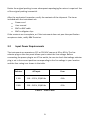
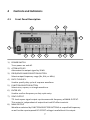
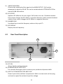
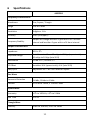
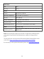
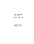
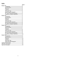
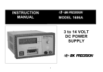
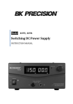
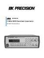
Model 4005DDS 5 MHz DDS Function Generator INSTRUCTION MANUAL 1 Safety Summary The following safety precautions apply to both operating and maintenance personnel and must be observed during all phases of operation, service, and repair of this instrument. Before applying power, follow the installation instructions and become familiar with the operating instructions for this instrument. GROUND THE INSTRUMENT To minimize shock hazard, the instrument chassis and cabinet must be connected to an electrical ground. This instrument is grounded through the ground conductor of the supplied, three-conductor ac power cable. The power cable must be plugged into an approved three-conductor electrical outlet. Do not alter the ground connection. Without the protective ground connection, all accessible conductive parts (including control knobs) can render an electric shock. The power jack and mating plug of the power cable meet IEC safety standards. DO NOT OPERATE IN AN EXPLOSIVE ATMOSPHERE Do not operate the instrument in the presence of flammable gases or fumes. Operation of any electrical instrument in such an environment constitutes a definite safety hazard. KEEP AWAY FROM LIVE CIRCUITS Instrument covers must not be removed by operating personnel. Component replacement and internal adjustments must be made by qualified maintenance personnel. Disconnect the power cord before removing the instrument covers and replacing components. Under certain conditions, even with the power cable removed, dangerous voltages may exist. To avoid injuries, always disconnect power and discharge circuits before touching them. DO NOT SERVICE OR ADJUST ALONE Do not attempt any internal service or adjustment unless another person, capable of rendering first aid and resuscitation, is present. 1 DO NOT SUBSTITUTE PARTS OR MODIFY THE INSTRUMENT Do not install substitute parts or perform any unauthorized modifications to this instrument. Return the instrument to B&K Precision for service and repair to ensure that safety features are maintained. WARNINGS AND CAUTIONS WARNING and CAUTION statements, such as the following examples, denote a hazard and appear throughout this manual. Follow all instructions contained in these statements. A WARNING statement calls attention to an operating procedure, practice, or condition, which, if not followed correctly, could result in injury or death to personnel. A CAUTION statement calls attention to an operating procedure, practice, or condition, which, if not followed correctly, could result in damage to or destruction of parts or the entire product. WARNING: Do not alter the ground connection. Without the protective ground connection, all accessible conductive parts (including control knobs) can render an electric shock. The power jack and mating plug of the power cable meet IEC safety standards. WARNING: To avoid electrical shock hazard, disconnect power cord before removing covers. Refer servicing to qualified personnel. CAUTION: Before connecting the line cord to the AC mains, check the rear panel AC line voltage indicator. Applying a line voltage other than the indicated voltage can destroy the AC line fuses. For continued fire protection, replace fuses only with those of the specified voltage and current ratings. CAUTION: This product uses components which can be damaged by electro-static discharge (ESD). To avoid damage, be sure to follow proper procedures for handling, storing and transporting parts and subassemblies which contain ESDsensitive components. 2 Compliance Statements Disposal of Old Electrical & Electronic Equipment (Applicable in the European Union and other European countries with separate collection systems) This product is subject to Directive 2002/96/EC of the European Parliament and the Council of the European Union on waste electrical and electronic equipment (WEEE), and in jurisdictions adopting that Directive, is marked as being put on the market after August 13, 2005, and should not be disposed of as unsorted municipal waste. Please utilize your local WEEE collection facilities in the disposition of this product and otherwise observe all applicable requirements. 3 Contents 1 Safety Summary ......................................................................................................... 1 2 Introduction................................................................................................................. 5 3 Installation ................................................................................................................... 5 4 5 3.1 Initial Inspection .............................................................................................. 5 3.2 Input Power Requirements.......................................................................... 6 Controls and Indicators .......................................................................................... 7 4.1 Front Panel Description ................................................................................ 7 4.2 Rear Panel Description .................................................................................. 8 Operating Instructions ............................................................................................ 9 5.1 Function Generator Output .......................................................................... 9 5.2 Duty Cycle Control ........................................................................................ 10 5.3 Function Generator Display Messages ................................................. 10 6 Specifications ........................................................................................................... 11 7 Certification .............................................................................................................. 13 8 Maintenance ............................................................................................................. 14 9 8.1 Preventive Steps ............................................................................................ 14 8.2 When the Unit is Not Turning On ........................................................... 14 8.3 Fuse Replacement ......................................................................................... 15 8.4 Instrument Repair Service ........................................................................ 15 Service Information ............................................................................................... 16 10 Limited One-Year Warranty............................................................................... 17 4 2 Introduction Description The B&K Precision model 4005DDS is a versatile 5 MHz DDS (direct digital synthesis) function generator with display up to 4 digits. The instrument generates sinusoidal, triangular, and square waveforms over the 1 Hz to 5 MHz range. The output voltage can be varied from 0 to 10 Vp-p into 50 ohms or to 20 Vp-p into open circuit. A continuously variable DC offset allows the output to be injected directly into circuits at the correct bias level. Features Frequency is selectable from 1 Hz to 5 MHz Sine, square, or triangle waveform output Direct digital synthesis (DDS) architecture Bright, easy-to-read LED display Number pad for quick input of frequency Front panel push button and pull knob can attenuate output by up to 40 dB 3 3.1 Installation Initial Inspection This unit is tested prior to shipment. It is therefore ready for immediate use upon receipt. The initial physical inspections should be made to ensure that no damage has been sustained during shipment. Inspect the packing box on receipt for any external damage. If any external damage is evident, remove the instrument and visually inspect its case and parts for any damage. If damage to the instrument is evident, a description of the damage should be noted on the carrier’s receipt and signed by the driver or carrier agent. Save all shipping packaging for inspection and contact the distributor from where the instrument was purchased. 5 Retain the original packing in case subsequent repackaging for return is required. Use of the original packing is essential. After the mechanical inspection, verify the contents of the shipment. The items included with the instrument are: Power cord User manual BNC to BNC cable BNC to alligator clips If the contents are incomplete, or if the instrument does not pass the specification acceptance tests, notify B&K Precision. 3.2 Input Power Requirements The instrument can operate on 115 or 230 VAC source at 50 or 60 Hz. The line selector plug on the rear panel allows you to select the line voltage. Before connecting the power plug to an AC line outlet, be sure to check that voltage selector plug is set in the correct position corresponding to the line voltage in your location and the fuse rating is as shown in the table. Selector AC Input Fuse 115V 110 – 120 V, 50/60 Hz 0.6A 230V 220 – 240 V, 50/60 Hz 0.3A Table 1 - Fuse Table 6 4 4.1 Controls and Indicators Front Panel Description 11 12 10 9 1 2 1) 2) 3) 4) 5) 6) 7) 8) 3 4 5 6 7 8 POWER SWITCH Turns power on and off. ATTENUATE KEY Attenuates the output signal by 20 dB. FREQUENCY RANGE SELECTION BUTTON Selects output frequency range (Hz, KHz, or MHz). DUTY CYCLE KEY Used to specify duty cycle of a square waveform. FUNCTION SELECTOR BUTTON Selects sine, square, or triangle waveform. ENTER KEY Used to confirm frequency or duty cycle entry. SYNC OUTPUT TTL level square signal output synchronous with frequency of MAIN OUTPUT. This output is independent of output level and DC offset controls. MAIN OUTPUT Waveform selected by FUNCTION SELECTOR BUTTONS at a specified frequency as well as the superimposed DC OFFSET voltage is available at this output. 7 9) AMPLITUDE KNOB Controls the amplitude of the signal at the MAIN OUTPUT. Pull knob to attenuate the signal by 20 dB. This can be combined with ATTENUATE KEY for total of 40 dB attenuation. 10) DC OFFSET Applies a DC offset to the main signal. Pull knob to turn on. Clockwise rotation from center changes the DC offset in a positive direction, while counterclockwise rotation from center changes the DC offset in a negative direction. 11) NUMBER PAD Use these keys to set the frequency value or duty cycle %. 12) LED DISPLAY Displays the set frequency. 4.2 Rear Panel Description 14 15 13 13) DC FAN 40 mm fan for cooling purposes. 14) KENSINGTON SECURITY SLOT For use with Kensington locks to secure your product and prevent theft. 15) INPUT AC POWER SELECTOR AND FUSE Power input socket and fuse compartment. Refer to arrow mark on fuse plug and mark on panel for selected input line voltage. 8 5 5.1 Operating Instructions Function Generator Output Before applying power to the unit, make sure that input voltage is correct and the ventilation holes are not blocked. Ensure the ventilation fan is working well. It is necessary to inspect the generated signal with an oscilloscope before connecting it to any electronic circuit. Hence, use of oscilloscope is mentioned in the procedure. Turn on the instrument with power on switch provided on the front panel. The display LED will light up. 1. 2. 3. 4 5. 6. Select the type of waveform required by pushing the corresponding function button. Connect the main output signal to CH1 of oscilloscope and the SYNC output signal to CH2 of oscilloscope. Set the trigger source of oscilloscope to CH2. Set the output frequency of the signal by the frequency control keys. The display shows the number immediately. If the input number is more than a 4digit number, the unit will clear all the digits but keep the last digit number and start again. Press the frequency unit button in “Range” to set the value of the input number. The output of the function generator will be the new output. Adjust the amplitude of the signal with the AMPLITUDE KNOB. Pull the knob if the signal is to be attenuated by 20 dB. If the ATTENUATE KEY is also activated while the knob is pulled, the signal will be attenuated by 40 dB. Set the DC offset of the signal by the DC OFFSET KNOB to the required level (-10 V to +10 V). Note: Check the impedance of the load before connecting. To get an accurate representation of the signal and prevent reflection, it is important to match this impedance to the output impedance of the function generator. 9 5.2 Duty Cycle Control The DUTY CYCLE KEY can be used to alter the symmetry of a square waveform. Symmetry variation amounts to changing the duty cycle, a ratio of “high” to “low” time, effectively converting the instrument into a pulse generator. 1. 2. 3. 4. Press the DUTY CYCLE KEY and the display will blink. Use the number keys to input the duty cycle percentage value (between 20% 80% can be entered). Press the ENTER KEY to execute duty cycle adjustment. The instrument will then return to the frequency display. If you want to change the duty cycle percentage value while the instrument is under duty cycle mode, repeat steps 1-3 above. To turn off duty cycle, press the DUTY CYCLE KEY two times and the duty cycle LED will turn off. Note: The duty cycle adjustment mode only functions for a square waveform and at frequencies below 3 MHz. 5.3 Function Generator Display Messages The LED display will show 1.000 kHz after power on. If the user inputs a frequency value, the LED display will blink until the user presses the ENTER KEY to execute it. If there is an input error, the LED display will show one of the following messages: Err02, Err-03, Err-04, or Err-05. The display will hold this error message for about 3 seconds and then return to the previous display. Error Code Description Err-02 Input value is too large Err-03 Input value is too small Err-04 Over the key waiting time, did not press ENTER KEY Err-05 Duty cycle frequency is higher than 3 MHz Table 2 - Error Codes 10 6 Specifications 4005DDS Frequency Characteristics Waveforms Sine, Square, Triangle Range 1 Hz to 5 MHz Resolution 4 digits or 1 Hz Accuracy 0.02% (200 ppm)* Frequency Stability Output will change less than 1 ppm within a 15 minute interval and less than 2 ppm within a 24 hour interval. Output Characteristics Impedance 50 Ω ± 2% Amplitude Range Variable control from 20 mVpp to 20 Vpp (open circuit); 10 mVpp to 10 Vpp (into 50 Ω) Attenuation -20 dB ± 2%, -40 dB ± 2% DC Offset Variable ±10 V (open circuit); ±5 V (into 50 Ω) Duty Cycle Adjustable 20% - 80% to 3 MHz for square Sine Wave Harmonic Distortion -50 dBc, DC to 20 kHz -30 dBc, 20 kHz to 5 MHz Flatness ± 0.3 dB to 1 MHz, ± 1 dB to 5 MHz Square Wave Symmetry ± 2% to 100 kHz, ± 5% to 5 MHz Rise Time ≤ 35 ns Triangle Wave Linearity ≥ 98% to 100 kHz, ≥ 95% to 5MHz 11 SYNC Output Level ≥3V Rise Time ≤ 25 ns General AC Input 115/230 VAC, 50/60 Hz Operating Temperature 32 °F to 104 °F (0 °C to 40 °C) Humidity 10% - 80% R.H. Storage Temperature -4 °F to 158 °F (-20 °C to 70 °C) Storage Humidity 0% - 90% R.H. Dimensions (W x H x D) 11” x 4” x 11.7” (279.4 x 101.6 x 297.2 mm) Weight 5.05 lbs (2.3 kg) Instruction manual, power cord, BNC to BNC cable, BNC to alligator clips *Applies to frequencies ≥ 1 kHz. Supplied Accessories NOTE: All specifications apply to the unit after a temperature stabilization time of 15 minutes. Specifications and information are subject to change without notice. To ensure the most current version of this manual, please download the current version here: http://www.bkprecision.com/search/manual/4005DDS For current up-to-date product information, please visit www.bkprecision.com 12 7 Certification CE Compliant CE Declaration of Conformity The function generator meets the requirements of 2006/95/EC Low Voltage Directive and 2004/108/EC Electromagnetic Compatibility Directive. Low Voltage Directive - EN61010-1:2001 o Safety requirements for electrical equipment for measurement, control, and laboratory use. EMC Directive - EN 61000-6-2:2005 - EN 61000-6-4:2007 - EN 61326-1:2006 o Electrical equipment for measurement, control, and laboratory use. 13 8 Maintenance 8.1 Preventive Steps Please follow these preventive steps to ensure the proper operation of your instrument. 8.2 Never place heavy objects on the instrument. Never place a hot soldering iron on or near the instrument. Never insert wires, pins, or other metal objects into ventilation fan. Never move or pull the instrument with power cord or output lead. More importantly, never move the instrument when the power cord or output lead is connected. Do not obstruct the ventilation holes in the rear panel as this will increase the internal temperature. Do not operate the instrument with the cover removed unless you are a qualified service technician. Clean and recalibrate the instrument on a regular basis to keep the instrument looking nice and working well. Remove any dirt, dust, and grime whenever they become noticeable on the outside cover using a soft cloth moistened with a mild cleaning solution. When the Unit is Not Turning On Check if the power ON/OFF switch is turned ON. If not, then check the power cord. Please make sure that the power cord is properly connected to the unit. Please also check the main switch and ensure that the AC supply at your site is the same as the one mentioned at the rear chassis of the unit. Check for a blown fuse. 14 8.3 Fuse Replacement If the fuse blows, the LED will not light and the instrument will not operate. Replace only with the correct value fuse. Refer to Table 1 - Fuse Table for fuse values. The fuse is located on the rear panel adjacent to the power cord receptacle. Remove the fuse holder assembly as follows: 1. Unplug the power cord from the rear of the instrument. 2. Insert a small screwdriver in the fuse holder slot (located between fuse holder and receptacle). When reinstalling fuse holder, be sure that the fuse is installed so that the correct line voltage is selected. To verify this, check the inscription on the surface of the fuse box. At the top left and bottom right corner, the line voltage rating is labeled along with a small arrow. Pick the line voltage to use and match the arrow on the bottom right corner. On the rear panel, there is also a label that says “LINE VOLT.” with an arrow. Match the line voltage inscription of the fuse box to this arrow to select that line voltage. 8.4 Instrument Repair Service Because of the specialized skills and test equipment required for instrument repair and calibration, many customers prefer to rely upon B&K Precision for this service. We maintain a network of B&K Precision authorized service agencies for this purpose. To use this service, even if the instrument is no longer under warranty, follow the instructions given in the Warranty Service Instructions section of this manual. There is a nominal charge for instruments out of warranty. 15 9 Service Information Warranty Service: Please go to the support and service section on our website at www.bkprecision.com to obtain an RMA #. Return the product in the original packaging with proof of purchase to the address below. Clearly state on the RMA the performance problem and return any leads, probes, connectors, and accessories that you are using with the device. Non-Warranty Service: Please go to the support and service section on our website at www.bkprecision.com to obtain an RMA #. Return the product in the original packaging to the address below. Clearly state on the RMA the performance problem and return any leads, probes, connectors, and accessories that you are using with the device. Customers not on an open account must include payment in the form of a money order or credit card. For the most current repair charges, please refer to the service and support section on our website. Return all merchandise to B&K Precision Corp. with pre-paid shipping. The flatrate repair charge for Non-Warranty Service does not include return shipping. Return shipping to locations in North America is included for Warranty Service. For overnight shipments and non-North American shipping fees, please contact B&K Precision Corp. B&K Precision Corp. 22820 Savi Ranch Parkway Yorba Linda, CA 92887 www.bkprecision.com 714-921-9095 Include with the returned instrument your complete return shipping address, contact name, phone number, and description of problem. 16 10 Limited One-Year Warranty B&K Precision Corp. warrants to the original purchaser that its products and the component parts thereof will be free from defects in workmanship and materials, for a period of one year from date of purchase. B&K Precision Corp. will, without charge, repair or replace, at its option, defective product or component parts. Returned product must be accompanied by proof of the purchase date in the form of a sales receipt. To obtain warranty coverage in the U.S.A., this product must be registered by completing a warranty registration form on our website www.bkprecision.com within fifteen (15) days of purchase. Exclusions: This warranty does not apply in the event of misuse or abuse of the product or as a result of unauthorized alterations or repairs. The warranty is void if the serial number is altered, defaced, or removed. B&K Precision Corp. shall not be liable for any consequential damages, including without limitation, damages resulting from loss of use. Some states do not allow limitations of incidental or consequential damages. So the above limitation or exclusion may not apply to you. This warranty gives you specific rights and you may have other rights, which vary from state-to-state. B&K Precision Corp. 22820 Savi Ranch Parkway Yorba Linda, CA 92887 www.bkprecision.com 714-921-9095 17 (Page intentionally left blank) 22820 Savi Ranch Parkway Yorba Linda, CA 92887 www.bkprecision.com © 2014 B&K Precision Corp. Printed in Taiwan v4.14.2014