1
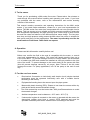
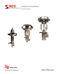
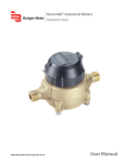
® Badger Meter Europa GmbH MN 05 series Oval gear flow meter INSTRUCTION AND OPERATION MANUAL January 2009 IND_MN05_BA_02_0901 Model MN05 1. Basic safety recommendations .......................................................................... 1 2. Repairs .................................................................................................................. 1 3. To the owner ......................................................................................................... 2 4. Operation .............................................................................................................. 2 5. For the use in ex-zones ....................................................................................... 2 6. Model MN05 .......................................................................................................... 3 6.1 General information ................................................................................................... 3 6.2 Installation ................................................................................................................. 3 6.3 Pulser details ............................................................................................................. 3 6.4 Maintenance .............................................................................................................. 4 6.5 Display parts listing ................................................................................................... 4 6.6 Meter specifications .................................................................................................. 5 6.7 Trouble shooting ....................................................................................................... 6 7. Warranty................................................................................................................ 6 8. Return of goods for repair / harmlessness declaration .................................... 7 Basic safety recommendations 1/7 1. Basic safety recommendations The manufacturer is not liable for damages that result from improper or not in accordance with the requirements use. The meters are constructed according to state-of-the-art technology and tested operationally reliable. They have left the factory in a faultless condition concerning safety regulations. The mounting, electric installation, taking into operation and maintenance of the meter may only be carried out by suitable technicians. Furthermore the operating personnel has to be trained by the operating authority and the instructions of this manual have to be followed. Basically, you have to respect the regulations for the opening and repairing of electrical equipment valid in your country. 2. Repairs Should you send back a flow meter in operation, please take notice of the following points: • Please enclose a description of the error as well as a precise statement of the measured medium (if necessary a safety specification sheet). • The meter has to be in a cleaned condition (outside and inside). Especially with harmful measuring mediums you have to pay attention that there are no impurities nor residues in the pipe or at the connections. • If it is not possible to clean the meter completely, particularly with harmful materials, do not send back the meter. • Please copy and fill in the harmless declaration at the end of this manual and send it back together with the meter to be repaired. We reserve the right to repair only cleaned meters. Costs, which result from insufficient cleaning, will be charged to you. IND_MN05_BA02_0901 To the owner 2/7 3. To the owner Thank you for purchasing a MN series flow meter. Please take a few minutes to read through this manual before installing and operating your meter. If you have any problems with the meter, refer to the maintenance and trouble shooting sections of this manual. This manual contains connection and operating instructions for the MN1 series meters. If you need further assistance, contact us or your local representative for advice. The MN series flow meter has incorporated the oval rotor principle into its design. This has proven to be a reliable and highly accurate method of measuring flow. Exceptional repeatability and high accuracy over a wide range of fluid viscosities and flow rates are features of the MN series flow meter design. The low pressure drop and high pressure rating means the MN series flow meter is suitable for both gravity and pump (in-line) applications. The meter is preferrably used for the measurement of lubricants. Other fluids on request. 4. Operation Please read this information carefully before use! Before use, confirm the fluid to be used is compatible with the meter, or consult your local representative for advice. This meter will handle particle sizes up to 0.075 mm/0.0003”. To prevent damage from dirt or foreign matter, we recommend a Y or basket type 200 mesh strainer be installed as close as possible to the inlet side of the meter. To prevent damage to the meter slowly fill the system with fluid (this will prevent damage caused by air purge). Note: Failure to do this could damage the meter. For pump applications, turn off the pump at the end of each day. 5. For the use in ex-zones • Reed switch: Connection to intrinsically safe electric circuit (simple electrical equipments must be operated intrinsically safe with a suitable barrier according to EN 50020). • Equipotential bonding has to be ensured upon the pipe system. • Meters with plastic housing (PPS): Please do not clean the meters with a dry cloth as this would cause electrostatic charge. • The fluid conductivity must be better than 1000 pico/Siemens/meter to avoid electrostatic charges. • Ambient temperature must be between - 20°C and + 40°C (T4). • If electronical register is mounted on the meter or operated with the meter, the electronical register must have a current ATEX approval and must be operated intrinsically safe with a suitable barrier according to EN 50020. IND_MN05_BA02_0901 Model MN05 3/7 6. Model MN05 6.1 General information The MN05 series flow meters are available in either PPS (Polyphenylene Sulfide Resin) or 316 stainless steel. Standard rotors are made from 316 stainless steel with optional PPS rotors with Hastelloy C shafts available. 6.2 Installation 1. Use thread sealant on all pipe threads. 2. Ensure the meter is installed so that rotor shafts are always in a horizontal plane. Flow is bi-directional. 3. We recommend use of flexible connections. 4. Extreme care must be taken when installing the meter. Pipe strain or over tightening meter connections can cause meter damage. 6.3 Pulser details Hall effect sensor specifications: • • • • 4.5V to 24V (4.6 ~ 9mA) operation needs only an unregulated supply. Open collector 25mA output NPN compatible with digital logic. Reverse battery protection. Temperature –40°C / -40°F ~150°C / 300°F. • • • Black White Hall Effect Sensor Wiring Details Reed relay specifications: • • Red Yellow Two wire SPST N/O. Switching voltage 150VDC maximum current 0.25 AMPS. Rating 3 watts. Temperature –40°C / -40°F ~150°C / 300°F. Duty cycle 20% on 80% off Red wire On BC2 = 6 Black wire On BC2 = 5 White wire On BC2 = 4 Yellow wire Green wire Hall sensor power (+) Hall sensor negative (-) Hall sensor signal Reed sensor connection Reed sensor connection Green Reed Switch Wiring Details Hall voltage range 4,5 – 24V DC Hall max rated current 25mA Hall connection Reed max voltage 1K ohm pull up resistor fitted 30V Reed max current 0,5A Reed life (typical) 500 x 10^6 cycles 10VDC at 10mA IND_MN05_BA02_0901 Model MN05 6.4 4/7 Maintenance Disassembly: 1. Ensure the fluid supply to the meter has been disconnected, and the line pressure has been released before disassembly. 2. Remove four (4) screws (Item 3) and remove the meter body cover (item 2). 3. Remove o-ring (item 5) and inspect (replace o-ring if damaged). 4. Remove rotors (item 4), clean and inspect (replace rotors if damaged). Reassembly: 1. Place rotors (item 4) into the meter body. The rotors should be at 90° to each other. Note: The rotor with magnets must be placed in the body on the same side as the groove on the body (refer to diagram). 2. Lightly rotate the rotors (item 4) by hand (they must rotate freely). 3. Install o-ring (item 5). 4. Replace the meter cap (item 2). Note: The groove on the cover must line up with the groove on the meter body (refer to diagram). 5. Replace four screws (item 3). CAUTION: Care must be taken not to overtighten the screws (item 3) or damage may occur. 6.5 Display parts listing IND_MN05_BA02_0901 Modell MN05 5/7 Description Item No. Rec. Part or set No. Off. Parts (order from this column only) 1 1 1 1 2 2 2 2 3 3 4 5 5 5 6.6 1 1 1 1 1 1 1 1 4 4 2 1 1 1 u u u u u u u u u u MS600BS MS600NS MS605BS MS605NS MS3R-S MS3S-S MS3R-SR MS3S-SR MS98s MS113s MS601S BS127Vs BS127Ps BS127Es Meter body assy. (BSP) stainless steel Meter body assy. (NPT) stainless steel Meter body assy. (BSP) Aluminium Meter body assy. (NPT) Aluminium Meter cap hall effect sensor Aluminium Meter cap hall effect sensor Meter cap reed switch Aluminium Meter cap reed switch Screws Aluminium Screws stainless steel Rotor set stainless steel O-Ring (Viton) O-Ring (Perfluro Elastomer) O-Ring (EPDM) Meter specifications Meter type Pulse Flow ranges (litres per hour/US gallons per hour) Above 1 mPas 0.5 to 50 l/h Below 1 mPas 1 to 50 l/h Accuracy of reading +/- 1% Maximum viscosity 1000 mPas Maximum operating pressure 500/1000 kPa Maximum operating temperature 80°C / 120°C Pulse type Hall effect sensor / reed switch Pulses per litre/US gallons 1552 Meter dimensions 50 x 50mm / 1.97” x 1.97” (meter body) 60mm / 2.58” (port face to face) Weight 240g / 8.5oz IND_MN05_BA02_0901 Warranty 6.7 6/7 Trouble shooting Trouble Fluid will not flow through the meter Reduced flow through the meter Meter reading inaccurate Meter not giving a pulse signal Trouble shooting guide Cause Remedy A) Dismantle meter, clean A) Foreign matter blocking rotors (strainer must be rotors fitted in line). B) Clean strainer B) Line strainer blocked C) Replace rotors (strainer C) Damaged rotors must be fitted in line) D) Meter connections over- D) Re-adjust connections tightened A) Line strainer partially A) Clean strainer blocked B) Fluid is too viscous B) Maximum viscosity 1000 mPas A) Fluid flow rate is too low A) See specifications for min.and max. flow rates or too high B) Air in fluid C) Excess wear caused by incorrect installation A) Faulty hall effect sensor or reed switch B) Faulty magnet C) Rotors installed in wrong position B) Bleed air from system C) Check meter body and rotors A) Replace meter cap B) Replace rotors C) Refer to correct rotor positioning – assembly instructions 7. Warranty Badger Meter warrants meters and parts manufactured and supplied by it hereunder to be free from defects in materials and workmanship for a period of 18 months from date of shipment or 12 months from date of installation, whichever period shall be shorter. If within such period any meters or parts shall be proved to seller´s satisfaction to be defective, such meters or parts shall be repaired or replaced at seller´s option. seller´s obligation hereunder shall be limited to such repair and replacement and shall be conditioned upon seller´s receiving written notice of any alleged defect within 10 days after its discovery and, at seller´s option, return of such meters or parts to seller, f.o.b. its factory. THE FOREGOING WARRANTY IS EXCLUSIVE AND IN LIEU OF ALL OTHER EXPRESS OR IMPLIED WARRANTIES WHATSOEVER INCLUDING BUT NOT LIMITED TO IMPLIED WARRANTIES (EXCEPT OF TITLE) OF MERCHANTABILITY AND FITNESS FOR A PARTICULAR PURPOSE. Badger Meter shall not be liable for any defects attributable to acts or omissions of others after shipment, nor any consequential, incidental or contingent damage whatsoever. Note: This warranty does not form part of, nor does it constitute, a contract between Badger Meter and the end user. It is additional to any warranty given by the seller of the products and does not exclude, limit, restrict or modify the rights and remedies conferred upon the end user, or the liabilities imposed on the seller, by any statute or other laws in respect of the sale of the product. IND_MN05_BA02_0901 Return of goods for repairs / harmlessness declaration 7/7 8. Return of goods for repair / harmlessness declaration Please copy, fill in and sign hereafter harmlessness declaration and enclose it for any return of goods you may send back for repair. No repair will be performed prior to receiving the harmlessness declaration duly filled and signed. Harmless declaration To : __________________________________________________________ Attn. : __________________________________________________________ From : __________________________________________________________ Dept. : __________________________________________________________ Please note that no repair will be performed prior to receiving of this declaration duly singed by you! Please send all parts clean from medium and inform us about possible medium wastes remaining in the part. For this purpose, please use this form. A security specification sheet of the medium must accompany this declaration in the following cases: Toxical, dangerous or objectionable media, or media belonging to any dangerous materials class. We inform you that uncleaned parts lead to additional costs. Extra clean costs will be charged to you. Furthermore, we reserve us the right to send the parts back to you for cleaning! Declaration We herewith confirm that the part(s) sent for repair has/have been cleaned and is/are free of any liquid and/or solid wastes of the medium and/or cleaning medium: Any eventually remaining wastes are: harmless dangerous, toxic, etc. – Security specifications are attached Signature of person in charge: ______________________________ Name of the person in charge in capital letters: ______________________________ Date: ______________________________ Company stamp: ______________________________ IND_MN05_BA_02_0810 Hotline Tel. Fax ® +49-7025-9208-0 +49-7025-9208-15 Badger Meter Europa GmbH Subsidiary of Badger Meter, Inc. Nürtinger Strasse 76 72639 Neuffen (Germany) E-mail: [email protected] www.badgermeter.de