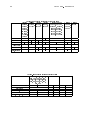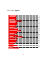
1
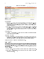
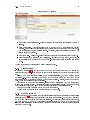
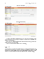
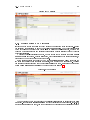
IPCorder User manual April 14, 2009 2 Contents 1 Introduction 5 1.1 System description . . . . . . . . . . . . . . . . . . . . . . . . . . . . . . . . . . . . 5 1.2 System requirements . . . . . . . . . . . . . . . . . . . . . . . . . . . . . . . . . . . 6 2 Management 2.1 2.2 2.3 2.4 2.5 2.6 2.7 2.8 7 Conguration . . . . . . . . . . . . . . . . . . . . . . . . . . . . . . . . . . . . . . . 7 2.1.1 Network settings . . . . . . . . . . . . . . . . . . . . . . . . . . . . . . . . . 7 2.1.2 E-Mail . . . . . . . . . . . . . . . . . . . . . . . . . . . . . . . . . . . . . . 8 2.1.3 Time settings . . . . . . . . . . . . . . . . . . . . . . . . . . . . . . . . . . 9 2.1.4 Storage settings . . . . . . . . . . . . . . . . . . . . . . . . . . . . . . . . . . 9 2.1.5 FTP . . . . . . . . . . . . . . . . . . . . . . . . . . . . . . . . . . . . . . . . 10 2.1.6 Remote access (UPnP settings) . . . . . . . . . . . . . . . . . . . . . . . . . 11 System . . . . . . . . . . . . . . . . . . . . . . . . . . . . . . . . . . . . . . . . . . . 14 2.2.1 Switching o / Restarting . . . . . . . . . . . . . . . . . . . . . . . . . . . . 14 2.2.2 Firmware upgrade . . . . . . . . . . . . . . . . . . . . . . . . . . . . . . . . 14 2.2.3 Factory settings . . . . . . . . . . . . . . . . . . . . . . . . . . . . . . . . . . 15 2.2.4 System log Devices . . . . . . . . . . . . . . . . . . . . . . . . . . . . . . . . . . . . 15 . . . . . . . . . . . . . . . . . . . . . . . . . . . . . . . . . . . . . . . . . . 15 2.3.1 Detection . . . . . . . . . . . . . . . . . . . . . . . . . . . . . . . . . . . . . 15 2.3.2 Manual Entry . . . . . . . . . . . . . . . . . . . . . . . . . . . . . . . . . . . 16 2.3.3 Managing devices . . . . . . . . . . . . . . . . . . . . . . . . . . . . . . . . . 17 2.3.4 Removal . . . . . . . . . . . . . . . . . . . . . . . . . . . . . . . . . . . . . . 20 2.3.5 Print credentials . . . . . . . . . . . . . . . . . . . . . . . . . . . . . . . . . 20 Monitors . . . . . . . . . . . . . . . . . . . . . . . . . . . . . . . . . . . . . . . . . . 20 2.4.1 Adding 20 2.4.2 Managing . . . . . . . . . . . . . . . . . . . . . . . . . . . . . . . . . . . . . 21 2.4.3 Removing . . . . . . . . . . . . . . . . . . . . . . . . . . . . . . . . . . . . . 21 Views . . . . . . . . . . . . . . . . . . . . . . . . . . . . . . . . . . . . . . . . . . . . . . . . . . . . . . . . . . . . . . . . . . . . . . . . . . . . . . . . . . . . . . . . . . . . . . . . . . . . . . . . . . . . . . . . . . . . . . . 21 2.5.1 Adding 22 2.5.2 Managing . . . . . . . . . . . . . . . . . . . . . . . . . . . . . . . . . . . . . 23 2.5.3 Removing . . . . . . . . . . . . . . . . . . . . . . . . . . . . . . . . . . . . . 23 Rules . . . . . . . . . . . . . . . . . . . . . . . . . . . . . . . . . . . . . . . . . . . . 23 2.6.1 Adding 24 2.6.2 Managing . . . . . . . . . . . . . . . . . . . . . . . . . . . . . . . . . . . . . 26 2.6.3 Removing . . . . . . . . . . . . . . . . . . . . . . . . . . . . . . . . . . . . . 26 Schedules . . . . . . . . . . . . . . . . . . . . . . . . . . . . . . . . . . . . . . . . . . . . . . . . . . . . . . . . . . . . . . . . . . . . . . . . . . . . . . . . . . . . . . . . . . . . . . . . . . . . . . . . . . . . . . . . . . . . . 26 2.7.1 Adding 26 2.7.2 Managing . . . . . . . . . . . . . . . . . . . . . . . . . . . . . . . . . . . . . 27 2.7.3 Removing . . . . . . . . . . . . . . . . . . . . . . . . . . . . . . . . . . . . . 27 Users . . . . . . . . . . . . . . . . . . . . . . . . . . . . . . . . . . . . . . . . . . . . 27 2.8.1 Types and permissions . . . . . . . . . . . . . . . . . . . . . . . . . . . . . . 27 2.8.2 User preferences 2.8.3 Adding 2.8.4 Changing settings . . . . . . . . . . . . . . . . . . . . . . . . . . . . . . . . . 28 . . . . . . . . . . . . . . . . . . . . . . . . . . . . . . . . . . . . . . 28 . . . . . . . . . . . . . . . . . . . . . . . . . . . . . . . . 3 29 4 CONTENTS 2.9 2.8.5 Changing password . . . . . . . . . . . . . . . . . . . . . . . . . . . . . . . . 29 2.8.6 Removing . . . . . . . . . . . . . . . . . . . . . . . . . . . . . . . . . . . . . 29 Switching o . . . . . . . . . . . . . . . . . . . . . . . . . . . . . . . . . . . . . . . 30 3 Live View and live data 31 4 Recordings 33 4.1 Viewing recordings . . . . . . . . . . . . . . . . . . . . . . . . . . . . . . . . . . . . 33 4.1.1 34 Exporting video . . . . . . . . . . . . . . . . . . . . . . . . . . . . . . . . . 5 Reference 5.1 5.2 37 Rules language . . . . . . . . . . . . . . . . . . . . . . . . . . . . . . . . . . . . . . 37 5.1.1 Syntax and semantics . . . . . . . . . . . . . . . . . . . . . . . . . . . . . . 5.1.2 Data types 38 . . . . . . . . . . . . . . . . . . . . . . . . . . . . . . . . . . . . 39 5.1.3 Basic commands 5.1.4 Simple practical examples 5.1.5 Basic programming methods and language constructions . . . . . . . . . . . 42 5.1.6 Actions . . . . . . . . . . . . . . . . . . . . . . . . . . . . . . . . . . . . . . 43 5.1.7 Events . . . . . . . . . . . . . . . . . . . . . . . . . . . . . . . . . . . . . . . 43 Terminology . . . . . . . . . . . . . . . . . . . . . . . . . . . . . . . . . . . . . . . . 43 . . . . . . . . . . . . . . . . . . . . . . . . . . . . . . . . . . . . . . . . . . . . . . . . . . . . . . . . . . . . 39 42 Chapter 1 Introduction IPCorder is a central management system for security devices (typically cameras and sensors), which employ the IP protocol. The system provides the following capabilities: Oers a `soft' interface, which handles all the complexities of the various device inputs, masking these from the user, thereby simplifying conguration considerably and oering centralized processing of the output. Automatically detects and congures new devices, then enters them into the system. Outputs from multiple sources (camera views, sensor statuses) can be organized, grouped, and viewed simultaneously. In other words the IPCorder can display a picture from various IP cameras/videoservers from dierent producers, values from them and possibly from other sensors, in unied user interface. Coordinates the activity of the sensors and cameras, and allows them to interact. Centralizes data storage (videos, images, values, ...) and provides an intuitive interface for searching and downloading records. Records event statistics, status changes, and based on these the system can execute various user-dened tasks (sending e-mail when an alarm occurs, turn a camera when a door is opened, and so on). For the automation of monitoring tasks, more experienced users will nd the scripting language provided is a powerful tool. For those less experienced, the simplied interface makes dening responses to events a matter of a few mouse clicks. All devices and the system itself can be controlled through the web interface. In the case of remote access (e.g., from the Internet), the system allows to drive a translation of inherent addresses on external ones dynamically, using a router/modem and a UPnP Port Forwarding function. Except the automatic setting the dynamical driving provides a higher system security, because the picture of the cameras is accessible from the external net (the Internet) only if a user is successfully loged in the IPCorder's web interface. Besides this option the IPCorder of course supports a manual setting of the addresses translation on the router/modem. tunneling of devices to external sites, so only the rewall's http port will be open. 1.1 System description At the heart of the IPCorder system is a hardware device that the user communicates with using its web interface. This means the user does not need to install any special software on his/her computer, a standard web browser is all that is required. The system is designed to be a centralized digital security control system . Its function is to centralize the management of digital security devices (cameras, sensors) and their data. 5 6 CHAPTER 1. The system can automatically detect and congure most devices INTRODUCTION (provided the device is supported). The system management allows the number of devices to be restricted at any given moment. Section 2.3 describes the conguration of controlled devices . providing interaction and linking The system acts as a communication node, between actions of devices, which are not aware of each other. This means, for example, triggering video recording from an alarm signal (which the camera would not be aware of without the presence of some additional system), or turning lights on based on a specic event. Apart from the basic reactions (such as triggering video recording when motion is detected), which are set up directly in the device's settings (see Section 2.3.3), the interactivity between events is handled by a set of user-dened rules. Section 2.6 describes how they are entered into the system. Storage of data is also managed by the system. The scenarios are entered, under which video should be recorded and for how long. The recordings are stored at a location in the central database, and can then be easily retrieved and reviewed. Sensor data can be exported in html table format, video and images from cameras can be downloaded into a le by a single click. Access to recorded data is described in Chapter 4. The system displays live data from sensors in a unied way, independently from the given de- vice. In contrast with traditional methods, where a separate browser window or separate program must be launched for each device, IPCorder allows outputs from multiple devices to be viewed simultaneously. First, the user selects a pool of devices, from which outputs are to be simultaneously monitored (dened as a `View'), then this particular pool can be displayed. Views can be saved and edited, so there is no need to start at the beginning every time. Viewing live device outputs is described in Chapter 3. 1.2 System requirements IPCorder is compatible with Microsoft Windows 2000, 2003, XP, Vista; Mac OS X 10.4 and 10.5 and Linux 2.6. IPCorder supports SATA and SATA 2 hard disk types, the two types can be freely combined. Using one of the following web browsers is mandatory for accesing the web interface: Mozilla Firefox version 2 or 3 (recommended), Internet Explorer 7 (for PC) or Safari versions 3.1 or 3.2 (for Mac). Each individual device requires various components in order to display its output in the browser for example Sun JAVA RE 6 Update 10 or higher, is recommended for proper display of the output from video-cameras. The viewing Java web applet Koukaadlo requires installation of MPEG4 plugin native libraries onto the client computer. In case the libraries are unavailable, the applet installs them automatically. Required specications of the computer the video is to be viewed on depend on devices used. 500MHz processor cycle quota and 50 MB of memory should be allowed for viewing the output from a single camera with the 1Mpx resolution. A minimal recommend coguration A is 2 GHz processor and 256 MB RAM. Heavy network loading should be expected during video transmission from the camera (or system) to the computer. It is recommended that an NTP server be accessible from the network to which the system is connected, so that the system may synchronize its date and time. Chapter 2 Management 2.1 Conguration On the rst start-up, IPCorder tries to obtain an IP address via DHCP ; if unsuccessful, the IP address defaults to 192.168.1.78. If the IPCorder is in the same subnet as the PC the IPCorder is to be accessed from, it should appear in Network Devices (under Microsoft Windows). If you are not sure with IP address of the IPCorder, you should use Utility IP Corder Discover application for discovering IPCorder device on your network. You can nd it on the supplied CD or download it from http://updates.ipcorder.com/. For correct running of IPCorder Discover utility Microsoft .NET 2.0 Framework is needed. Download for free from microsoft. com/ downloads/ . http: // www. If the Discover would not nd you IPCorder, switch o a rewall and try again. After entering the IP Address of the IPCorder in a www browser's address bar (Mozilla Firefox or Internet Explorer, for example), a login screen will display (provided that the system has been installed properly see the Installation Manual). The default password of the admin user (the administrator account) is admin. IP address , time , remote access, user accounts . These settings can be found from the menu Management , Conguration . On the rst use, certain settings need to be entered, such as and 2.1.1 Network settings In this section (Figure 2.1 on the following page) the parameters which determine how and where the application will be accessed on the local network can be set. If you are uncertain about any item please consult with your network administrator . Meanings for each of the items are as follows: Automatic conguration (DHCP) if DHCP (Dynamic Host Conguration Protocol) is selected then the IP address, subnet mask, gateway and DNS (Domain Name System) server settings will be ignored; the system will attempt to retrieve these settings from the central DHCP server Static IP settings: IP address the device will appear on the local network at this IP address Net mask the local network to which the device belongs Gateway IP address of the (gateway) device through which communication is directed to the internet and other external networks DNS Server the server from which the application can request IP addresses based on DNS names 7 8 CHAPTER 2. MANAGEMENT Figure 2.1: Network settings Domain settings: Host name DNS name for the computer, excluding the top level domain (e.g. from koukaam.se it is just koukaam ). If it has no name, localhost, may be entered. For outgoing emails to be sent, it is of course necessary for the SMTP server to accept messages from a machine with such name Domain top level domain under which the device will be assigned (e.g. from www.google.com it is just com ). If no domain is assigned to the device, localdomain, can be entered. For outgoing emails to be sent, it is of course necessary for the SMTP server to accept messages from this domain Pool of assigned IP: Starting / Ending adress denes a range of IP adresses which will IPcorder assign to the devices under its management Present like UPnP device: Enable Presentation this option switches on/o the function of the IPCorder UPnP Presentation. That means the device will be seen from other computers in the folder Network Places in Windows system (with the assumption Windows are congured correctly) Settings are conrmed by clicking the Apply changes button. 2.1.2 E-Mail IPCorder is able to notify the user about dierent events via automatically generated e-mails. It also supports dierent national character sets, which means it is possible to use diacritic symbols in the notication e-mails. To use the notication e-mail system, it is rst necessary to congure the parameters of the SMTP server. If you are not sure how to set it up, please contact your e-mail provider. SMTP Settings: SMTP Server Enter the address of the SMTP server for IPCorder's outcoming mail. Use SMTP Authentication Tick the checkbox if the SMTP server you are using requires authentication. 2.1. 9 CONFIGURATION Figure 2.2: SMTP settings User Name and Password Insert the security data necessary for accessing the SMTP server. Send Test Mail This feature allows you to test if the SMTP conguration is working properly. Provide your email address in the Recipient eld and press Send Test Mail button. You should receive the test message shortly. Otherwise, refer to the userlog in case a SMTP related error had occurred. Admin Email Fill in the e-mail address the system status messages should be sent to. Send email when rescue mode activated If this checkbox is ticked, IPCorder will automatically send notication to the admin e-mail address before switching into rescue mode. Conrm the settings by pressing the Apply Changes button. 2.1.3 Time settings In this form (Figure 2.3 on the next page) the method (and parameters) used to maintain the system's time can be set. The time set on the device is displayed at the right top corner of the form. allow NTP Synchronization ), the NTP Server should DNS name of the device with which the system should synchronize its time (preferably a server which is always online). Finally, enter the Area and City , where the application will be operating. In case that no NTP server is accessible, enter the time manually (type the current time in the Date and time eld). Alternatively, select the Synchronize with Computer option, If the NTP method is selected ( be entered, i.e., the IP address or which retrieves the time from the machine the user is accessing the application from. Click on the Apply Changes button to conrm the settings. Switch to summer time is automatic in accordance to time zone. 2.1.4 Storage settings Total capacity ) and about currently avaiable free disk space (Free space ). The button Congure RAID array allows changing the disk usage settings . IPCorder supports multiple array types, This page (Figure 2.4 on the following page) contains information about total disk capacity ( i.e. array types 0, 1, 5 and 10. This setting requires restarting the device to the rescue mode, which implies interuption of the recording process and disconection of all other users currently connected to the device. 10 CHAPTER 2. MANAGEMENT Figure 2.3: Time settings Figure 2.4: Storage settings The system automatically monitors free space on the disk where data is stored. If space becomes signicantly reduced, the oldest data will start to be erased until the available free space returns to a sucient level. In case a check box Purge data older than a specied limit is checked, data older than specied will be removed automatically. Click on the Apply Changes button to conrm the settings. 2.1.5 FTP The data recorded by IPCorder can be accessed through FTP protocol, which allows easy down- Enable FTP access check box Apply Changes button to conrm the settings. The username for FTP access is ftp and the option for setting the password is available in the FTP Password section. loading of large amounts of data. To enable FTP access, tick the and click on the 2.1. 11 CONFIGURATION Figure 2.5: FTP settings 2.1.6 Remote access (UPnP settings) If it is demanded the remote access to the IPCorder and cameras from other networks (e.g. using the Internet), it is necessary to set up the so-called remote access . For the successful access to the IPCorder and cameras the IPCorder must be placed in the local network, where on the boundary of the local network and Internet there is placed a router (Internet Gateway) capable of address translation. Whenever the remote access is demanded, we have to permit it by checking the option Enable Remote Access in the form. Further it is needed, with consideration of the router attributes, to choose one of two methods which provide the access. If the router supports the family of UPnP (or Universal Plug and Play ) protocols, the IPCorder can control the remote access dynamically, with no need of a manual set up. Thus the cameras are approachable only when the authorized user's watch them. In this case we choose the option Automatic Router Control at the upper part of the screen (2.6). Figure 2.6: UPnP settings The port through which the device is to be externally visible should be entered into the Web Port eld. If our outgoing Internet gateway (to the public Internet) has address 194.114.132.12, and the Web Port is set to 1024, then the address for a web browser on an external site would be 12 CHAPTER 2. MANAGEMENT Figure 2.7: Static port forwarding settings http://194.114.132.12:1024 (this is displayed as a link labeled Public URL). The Port Range is the space, in which the application will attempt to allocate ports through the gateway for access to controlled devices. The From and To values are inclusive. The Web Port must lie within this range. If the router does not fully support UPnP protocol, it is possible to make device accessible through static settings. Manual Router Setup is provided (Figure 2.7). The meaning of Web Port is the same as above. An IP address on which the device will be visible on Internet is required to ll in Public Router IP eld. For this case an option Port Range and After applying changes a table with router (Figure 2.8 on the facing page) settings is generated. It is possible to print in on screen by clicking on Print Static Tunnels button. The content of eld is this: Timestamp time of last change in settings. It is recommended to check it always when a settings of IPCorder is changed, a camera added or camera network setting changed. It is necessary for router to be synchronized with the most recently updated table. Device name of the device (camera), for which is required to make a translation record. IP address address of the target device, where data are sent. It is often labeled as Target IP address on routers. Target/To port port on device where data are re-sent. Together with IP address thay provide the nal destination of data. On routers it is often called as Target port or To port. Protocol protocol on IP base which is used. On routers it is often called as Protocol. Source/From port port on the outside side of router (gateway) where data should be re-sent. It is port from dened range. On routers it is often called as Source port or From port. The data from this table must be entered in router settings of port forwarding or NAT (for example using the router Asus WL500g the nal setting will bee similar to Figure 2.9 on the next page) and also must be updated, in correspondence with settings of IPCorder. If you are uncertain about any of these settings, please consult with your trator . network adminis- 2.1. 13 CONFIGURATION Figure 2.8: Table of forwards Figure 2.9: Router settings 14 CHAPTER 2. MANAGEMENT 2.2 System This section contains options as for actualization a rmware of the IPCorder so for restoring a factory settings of the device. Moreover it oers the description of a system log and possibility to restart or switch o the device. 2.2.1 Switching o / Restarting Power O / Restart Conguration menu, System . In the event that the device needs to be switched o or restarted, the buttons can be found by selecting the appropriate option in the (Figure 2.10). LEDs on the device indicate its current status (see the Installation Manual). Figure 2.10: Power O, Restart 2.2.2 Firmware upgrade To upgrade the device's rmware it is rst necessary to obtain a product key (Figure 2.11) by clicking the Get Product Key button on the rmware upgrade page, accessed from the conguration menu; the key is needed to generate the new rmware. The latest rmware is always available at http://updates.ipcorder.com. The firmware is unique for each device. It cannot be used on other devices. Firmware On the Conguration, Firmware Upgrade For a complete description please refer to the installation manual . Figure 2.11: Firmware upgrade Upgrade rescue mode . page, when the button is pressed the rmware is loaded onto the device in a special 2.3. 15 DEVICES 2.2.3 Factory settings The device can be switched to rescue mode and reset back to its factory settings (Figure 2.12). The exact procedure for performing a factory reset is hardware dependent and described in the installation manual . Figure 2.12: Factory reset 2.2.4 System log For detailed control of the device's function it is possible in the menu open the System log (Figure 2.13 on the next page). This you can Conguration , System Update or Delete using proper buttons. 2.3 Devices The system is able to control and synchronize various device types, usually cameras and sensors (thermometers). The range of devices supported by the system is given by installed rmware version (it determines which drivers will be installed into the system). Only a user with Administrator privileges can work directly with the devices and their settings. 2.3.1 Detection In order for the system to work with the device, it needs to be aware of it and have it congured. If the devices are connected to the same network segment, and are active, they can be auto- Management menu, select Devices to search for new devices. Select Discover and click the Discover button in the window. matically detected. In the the subheading After a moment, the system will display all devices, which have not yet been added to the system (Figure 2.15 on page 17). Control of these devices can now be passed to the application by selecting the ones that are required (click the appropriate Activate check box) and entering their basic parameters. The Device name is the required item. It is the name which users will see displayed for this device. This may contain spaces and diacritic characters. If the IP managed option is ticked the device will be assigned an IP address from the range set in section Section 2.1.1. If secure password access to a camera is desired, the Device is password protected box should be ticked and the camera's current username and password entered. Devices are added to the system when the Activate option is clicked. The password can be generated automatically 16 CHAPTER 2. MANAGEMENT Figure 2.13: System log Figure 2.14: Device detection Generate new password . The generated passwords can be printed later using Print Credentials from the menu. by ticking a eld a link 2.3.2 Manual Entry If the device is unreachable (e.g. on a dierent network), it can be entered manually. Manual Management , Devices , using device entry is selected from the same menu as automatic entry ( the Add Manually link. A form (Figure 2.16 on the next page) with elds for basic device identication will appear. Device Name eld is shown, as well IP address and its Type are also required. Again, the device's as the Authentication settings . The If we want to add only one device, we can conrm the values entered by clicking on the Activate button. If further devices are to be entered the Add Next button should be clicked. 2.3. 17 DEVICES Figure 2.15: New devices Figure 2.16: Manual device entry 2.3.3 Managing devices Changes to device settings and camera recording modes are made by clicking Devices , then Manage . When the appropriate device has been located in the list, click on Management , Settings . The elds, which were originally set (Figure 2.15) when the device was entered into the system can be edited in the form now displayed, as well as the following new elds: Network settings Authentication: Manage manages users accounts to this device. Advanced settings: Device Web specify behaviour of device more closely. Video settings displays the resolution of video and its format. 18 CHAPTER 2. MANAGEMENT Figure 2.17: Device list Figure 2.18: Device conguration Recording mode there are three modes in which cameras may operate: View only the camera does not record, and no events are received from it (no reaction using rules is possible using the digital input from a camera in this mode). The camera will however display a live image in the views. Recording on trigger the camera records whenever the specied event occurs. For every event occurrence, video recording will be triggered. The Before and After elds indicate how many seconds of video should be recorded before and after the event, respectively. Before and 0 - 60 After , respectively. Two types of event may be selected: Trigger by motion detect video is recorded whenever the camera reports motion Permitted range of the parameters is 0 - 4 seconds for the parameter seconds for the parameter in a set detection window. Trigger by input changes. video is recorded whenever the camera's digital input value 2.3. 19 DEVICES Permanent recording the camera continuously records video to les with the length set Video length eld. At the upper right corner of the form there is a eld Device Ident.. It contains very unique in the string generated from device's name which is used in rules denitions (Section 2.6). The Authentication: Manage eld allows access to the login details for the device. The following may be congured here (Figure 2.19), depending on the camera's properties: Enable Authentication Free Access to Camera if ticked, no security will be used when viewing the camera's images View Account authorization details used when viewing the camera's images. Username and Password Generate new password the system will automatically generate a password for viewing Enable authentication Free view access if this option is selected no authorization will be required for viewing the camera's output Special option Update IPCorder only serves to set the device password internally in IPCorder, where the device's password has been set by another method Administrator account authorization details used when conguring the camera Username and Password Generate new password the system will automatically generate a password for viewing Update IPCorder Only for setting up passwords for any device enciphered besides the IPCorder Figure 2.19: Camera Authorization Details 20 CHAPTER 2. MANAGEMENT 2.3.4 Removal If, for some reason, a device needs to be removed from the system (e.g. has become damaged, redundant, . . . ) the selected. Select the Management , Devices menu should be accessed and the Manage item The list of devices registered on the system is displayed (Figure 2.17 on page 18). Remove option for the desired device. The system will prompt for a conrmation of list of devices will be displayed again, but the the action. If the removal was successful, the removed device will no longer be listed. 2.3.5 Print credentials For reference purposes, a device's authorization details can be printed out (Figure 2.20). system will export a table of users and passwords for each registered device when the Credentials button is pressed. The Print Figure 2.20: Print credentials It is recommended that all credentials be printed o once all the devices have been installed, and the information stored in a safe place. 2.4 Monitors Only a user with Administrator privileges may access monitor settings. Monitors are system objects, which represent individual device outputs (camera's picture, temperature, ...). There are two types of the monitors: Variable dened by the user, they contain a list of sensors and system variables with their values. Live stream these are monitors with camera images. The system always reserves one for each camera. 2.4.1 Adding Variable monitors can be added through the Management , Views menu under the item Add a Monitor (monitors with the live stream are implicit in the system and are static). Every monitor must be assigned a Name . The user must also select at least one Device Variable pair. Variables for monitoring are added to the monitor by pressing the Add Next button; they are removed by clicking on the X at the end of the row where the variable is listed. 2.5. 21 VIEWS Figure 2.21: Editing a monitor The monitor is created when the Create button is pressed. 2.4.2 Managing The list of variables can be found under Management , Views , Manage Monitors . Figure 2.22: Monitor list If a monitor's properties need to be changed (e.g. adding a variable), the Settings link should be selected in the appropriate monitor's row. The same form will be displayed as for adding a new monitor (see Figure 2.21). Changes are saved by clicking the Apply Changes button. 2.4.3 Removing Management , Views , Manage Monitors ). Click on the Remove link at the end of the appropriate monitor's An undesired monitor may be removed from the same menu as it is managed ( row. 2.5 Views Views are user-dened groups of device outputs, which are convenient to view together in one browser window. A view is composed of monitors , which are single device outputs (camera 22 CHAPTER 2. image, or sensor MANAGEMENT value). The number of monitors to be displayed, their layout and content will be dened by the Views. Only a user with Administrator privileges or permission to congure Views and Monitors can access or change their congurations. 2.5.1 Adding To add a new View select Management , Views , and the Add item. Figure 2.23: View layout On the rst screen (Figure 2.23) a View name is entered for the View and its layout is monitors in the View and their relative position on selected. The layout denes the number of the page. When the Create button is pressed a second screen is displayed (Figure 2.24). Figure 2.24: Setting View content 2.6. 23 RULES The content of each cell may now be selected, by assigning a monitor to it. selection is composed of the pre-dened monitors . live stream monitors The available and the user-dened variable It is also possible to assign buttons to each View, which allow signals to be sent to the system. These signals are evaluated in the rules, and various actions may be initiated (see Section 2.6). Each button must be given a name (label) and the signal it will send out when pressed must be dened. Buttons may be added by pressing the Add a Button button, and may be removed by clicking the X next to the button's settings. If the Save Only button is pressed, the system will return to the View list. Save and View button the system will save and display the changes. 2.5.2 Managing If View settings need to be edited, the View menu. By pressing the Manage item should be selected from the Management , Figure 2.25: View list The list of existing Views is displayed (Figure 2.25). Each one has a Settings link, which allows its parameters to be edited. Only the content of individual cells and button settings may be edited for existing Views; the layout may not be changed. The conguration is the same as for creating a new View (see Section 2.5.1). 2.5.3 Removing If a View needs to be removed, select Manage from the Management , Views menu. The list Click the Remove link for the appropriate View to of Views will be displayed (Figure 2.25). remove it, and conrm when prompted. 2.6 Rules Rules are simple but very powerful tools to determine the system's reaction to an event . As a basic example, rules allow actions to be initiated such as: If it is not Saturday or Sunday and the temperature drops below 20 degrees, send an e-mail to [email protected]. action is bound to an arbitrary event in the system. Event sets are dependent on Basically, an devices that inaccessibility can be detected (device fault, network oine, . . . ). Cameras have events such as video recording , change of a camera's state (triggering, reconnection) and motion detection (if the camera supports this). Sensors indicate events where there is a change of state . For a list of events supported by individual are connected to the system. For each device, its devices see Table 5.3 on page 45. 24 CHAPTER 2. MANAGEMENT Simple rules can be entered by pointing and clicking in the form. More complex rules must be entered as text in the special rules language. Viewing and conguring rules is only allowed for users with 2.6.1 Adding Rules are added through the Administrator privileges. Management , Rules menu under the Add item. Figure 2.26: Selecting a rule's assignment type Rule Name is the name, which the user will see the rule displayed as. The Enabled check box is for easily deactivating the rule. The next section provides options for the schedules when the rule should be active (outside this schedule the rule is o ). If no schedule is checked, the rule will be active regardless of schedules. For more on schedules see Section 2.7. In the On section choose and event, which should execute the rule (e.g. a pair camera-motion detected). What happen after the triggering event is dened by the so called Execute blocks. Every execute block allows the user to dene a condition or a set of conditions and a set of actions to be taken when the conditions are fullled . always - the simplest option. Such a block will be executed at every occurence of the triggering event. when - allows to specify a simple condition for a system or device variable. when (advanced) - besides the same functionality as when allows more complex conditions e.g. comparison of two system variables or working with user events. when all of the following holds - allows for linking the conditions with AND. For the embedded contion the following is available: * * * * simple - for a condition of the type when pokro£ilá - for a condition of the type when (advanced) all o - for another layer of conditions linked with AND any o - for another layer of conditions linked with OR 2.6. 25 RULES when any of the following holds - allows for linking the conditions with OR . Types of the embedded conditions are the same as for the when all of the following holds variant. Implicitly two embedded conditions are generated, more conditions can be added by clicking the add condition link. In the next part the actions to be taken when a triggering event occurs and the conditions are fullled are dened. There are the following options: Device action - allows to pick a device and an action it should perform , e.g. trigger recording (In order to start recording the camera has to be in the mode recording on trigger. The argument species how long video - in seconds - should be recorded.) Send e-mail - displays a form for dening an email (to, subject, body) Set variable - allows to dene a user variable and set its value, which may be useful e.g. for testing this value in oter rules. Wait - allows the user to dene a delay before the execution of te next actions and blocks For adding another action to be executed the Add action button is available. Generally, this form allows for dening a rule that at the occurence of the triggering event examins several sets of conditions and based on their validity executes dened sets of actions. For advanced users an interface for editing rules is available - you can switch to it by clicking the Switch to text input link under the selection of schedules. Text input for rules is dened as follows: Name must be entered, whether it is Enabled , and its Schedule As previously, the rule's The text part then must contain a full denition of the rule, including device identiers, Settings event names, and any relevant variables. The rule's format is described in Section 5.1. Figure 2.27: Text input of a rule In all cases, the rule entered is conrmed by clicking Create . 26 CHAPTER 2. MANAGEMENT Figure 2.28: Rule list 2.6.2 Managing The list of rules is in the Management , Rules menu under the Manage item. When there are no rules selected this item is invisible. If the properties of a rule need to be changed (e.g. changing the email's text), the Edit link is selected for the appropriate monitor. The same form is displayed as for rule creation (see Section 2.6.1). Changes are saved by clicking the Apply Changes button. 2.6.3 Removing Management , Rules Manage item). To remove a rule, the Remove link is clicked for the appropriate Undesired rules are removed by accessing the same menu as for managing them (i.e., monitor. If a rule needs to be removed only temporarily, there is no need to remove it from the system. It is sucient to make the Enabled check box blank, by editing the rule's settings, or modifying the rule's Schedule Settings to match the required time periods. 2.7 Schedules Schedules represent time periods within the week. They are used to dene when rules are applied and the recording intervals for cameras. One important use is, for example, to separate time between working hours and non-working hours on the monitored premises. Which can be used protably for recording on motion detection only outside working hours and thus record only relevant footage. Setting and viewing schedules is only possible for users with 2.7.1 Adding Schedules are accessed through the Administrator privileges. Management , Schedules menu, by clicking the Add (Figure 2.29 on the facing page). Each schedule must be assigned a item Schedule Name , which will be used to identify it in the Period for each day it should operate. The Add other parts of the application, and the active Next button allows additional periods to be specied. Periods may be removed be clicking theX against the appropriate period. If two or more intervals (maximum number is twenty) are required on a single day, each interval needs to be entered as a separate item. For example, if we require an active period on Monday from 8am until 12am, and then from 1pm until 6pm, two rows must be entered; one will be for the Monday period from 8am until 12am, and the second for Monday 1pm until 6pm. Create button. The schedule is saved by clicking the 2.8. 27 USERS Figure 2.29: Editing Schedules 2.7.2 Managing The list of schedules is accessible through the age item. Management , Schedules menu under the Man- Figure 2.30: Schedule list Next to each schedule is a Settings link, for editing that schedule's properties. Clicking on the link will display the same form as for creating a new Schedule ( 2.29). Changes in the settings are saved by clicking Apply Changes . 2.7.3 Removing To remove a schedule select the Manage item from the Management , Schedules menu which is again invisible if no schedules are selected. All existing schedules are listed here (Figure 2.30). A schedule is removed by clicking on the Remove link for the appropriate schedule. 2.8 Users password , language settings , setting for how units are displayed, and not in the last row each user's permissions for accessing individual system functions can be dened. The application allows each user to hold an independent account. Each user has their own 2.8.1 Types and permissions For simplicity, the system oers basic grouping of users into Administrators and Users . 28 CHAPTER 2. MANAGEMENT Users may at any time monitor the current status of a device in the Views, and set their own history , manage Views and Monitors , and have remote access from other networks. Administrators have all the same permissions as users, but are also able to manage user accounts and the system itself (Devices , Views , Rules , , system settings ). preferences. They may also have permission to browse 2.8.2 User preferences All users have their own user preference settings, as well as their own password. In particular, the language settings for the program's user interface to be set. The decimal numbers format , date format and starting day of week may also be set. These settings may only be altered for the user's own account (under which he/she is cur- options allow the rently logged in). Changes are made by selecting Preferences , User Preferences from the Management menu (Figure 2.31). Figure 2.31: User preferences Press the Apply Changes button to conrm any changes. 2.8.3 Adding Only Administrator accounts allow new user accounts to be created. To add a new user account, the Users item is selected from the Management menu, the Add item is then selected. Figure 2.32: Adding a user 2.8. 29 USERS Figure 2.33: User list username and password (twice for verication) are entered. The user account type permissions are then selected. Everything is conrmed by clicking the Create button. The system will then display the list The and of users, showing any changes. 2.8.4 Changing settings Permission changes for a particular user's account may only be carried out by a user with Administrator privileges. Preferences may be set by the user in the User preferences . To make changes to a user account, select the Users item from the Management menu. The list of users will be displayed(Figure 2.33). Select the Manage option and click on the Settings link for the appropriate user. The same form appears as for Adding a User (Figure 2.32 on the preceding page), but without the option to set the username and password . Once the desired changes have been made conrm using the Apply Changes button. The system will conrm the action and display the list of users. 2.8.5 Changing password User preferences (Figure 2.31 on the facing User preferences item from the Management , PreferSelect Change Password then enter the old password once, followed by the new A user may change their own password in their page). To change password select the ences menu. password twice. Administrator 's account. Management , Users menu, select Manage (Figure 2.33). For the appropriate user, click on the Password link and enter the new password twice. Click the Set Password If a user's password is forgotten, it may be changed from an Through the button to conrm. 2.8.6 Removing Administrator . To remove a user account select the Users item from the Management menu (Figure 2.33). Select the Manage item and click the Remove link for the appropriate user account. The A user account may only be removed by an removal must then be conrmed. Following conrmation the list of users is displayed(Figure 2.33) and a message conrming the account's removal. 30 CHAPTER 2. MANAGEMENT 2.9 Switching o In the Management , System menu, the Power O/Restart device to be correctly switched o/restarted. (Figure 2.34) item allows the For complete turning o the device it could be necessary (in dependence on the type of the device see Installation Manual ) to disconnect it from the power supply. Figure 2.34: Restart Chapter 3 Live View and live data The application allows multiple device outputs to be viewed simultaneously, so there is no need to have a separate browser window open for each camera. This method of viewing multiple device views are about. Of course, they must rst be congured Management , Views menu (see Section 2.5). Then they can be displayed from the top Live View menu. First, the view should be selected from the menu at the top of the left sidebar (choose one outputs in a single window is what in the from the list). Figure 3.1: Displaying Views view , it will be displayed on the right hand side, where the area cells according to the view's settings. Each cell displays the chosen monitor (see Section 2.4). These may be monitors showing a camera's live stream (as in the left hand cell), or variables monitors , which contain a list of system variables (from sensors) After selecting a particular is divided into individual and their current values (as in the monitor on the right). active monitor (highlighted with the red live stream there are Maximize to enlarge the At any given moment, there will always be one border). If the active monitor contains the Snapshot to save a frame from the camera's current output buttons depicted on the control buttons will be displayed in the left sidebar. Depending on the type of camera, the buttons might be for swiveling , focus , iris change and zoom . IQin Vision cameras have a picture zoom feature: picture and left. For a camera, which supports remote control, a set of Zoom in : hold the left-hand mouse button down over the desired part of the image Zoom out : press the right-hand mouse button 31 32 CHAPTER 3. The LIVE VIEW AND LIVE DATA user-dened control buttons are displayed in the bottom left-hand corner. This buttons can be used protably for operating barriers, lights, heating etc. However for their correct use it is necessary to study the rules language (5.1). If the view's settings need to be changed, these can be accessed directly from the link, located above the User Buttons . View settings Chapter 4 Recordings 4.1 Viewing recordings Figure 4.1: History The system stores recorded video output on hard disk for later processing. According to the settings, it either records continuously or only if triggered by specic events (see Section 2.3.3). These recordings and search tools are accessible through the Recordings menu. A calendar is displayed on the left, which allows selection of the time span to be searched. The day or the week month (click on its name) may be device and the event type (see 5.3) to be monitored. (click on the arrow next to it), or the selected. On the right-hand side, select the Once the selection is made, the statistics for that time period are displayed. Graphs for more than one event may be displayed. Undesired graphs may be removed using the X in the graph's title X on the right side of the time axis. The selected Add creates new set and activates dialog box for naming it. For saving changes and removing the set use buttons Save and Delete . Holding the pointer over a colored bar of the graph will display the time period it represents. bar. All graphs may be removed by using the graphs constitute a Graph Set . The button For an event graph, the height of each bar represents the frequency of the event's occurrence. For a graph of values the bar represents the mean value over that time period. The recording history can be navigated both with the arrows in the title bar of the graph left-hand arrow for the previous interval, the right-hand arrow for the next one, the up arrow to lengthen the interval (from an hour period to a day, and so on)) and by clicking on (the 33 34 CHAPTER 4. a specic interval RECORDINGS which causes a detailed record of events is displayed for that particular time period. A green rectangle acting as a play button is displayed beneath the time intervals, which contain video. By clicking on it, the given interval's video content is replayed in the player window next to the graphs. The player is controlled using intuitive buttons similar to the ones found on most applications of this type: > Play || Pause >| Next item |< Previous item >|| Next shot ||< Previous shot There is a menu to select the speed the video is played at Zooming is possible here, in the same way as for live streams (see Chapter 3). A grey rectangle is displayed beneath the time intervals, which contain sensor values. By clicking on it, a new window opens displaying the measured values from the sensor for that time period (Figure 4.2).The browser's settings must allow pop-up windows to be opened. Only a limited number of values are displayed in the window (maximum 200 items), so if the interval contains too many values the interval needs to be dropped a level to the next shortest time interval. Figure 4.2: Exporting sensor values 4.1.1 Exporting video The stored video can be downloaded using the recordings interface (Chapter 4). The Get Video link saves the current video to a le and the Get Snapshot link saves the current video frame as an image. The exported video can be played using FFDShow decoding and possibly some other lters. Easiest way to watch these videos is to play them in VLC player, which already contains needed lters. It is available for free download at http://www.videolan.org/. FFDShow lter itself 4.1. 35 VIEWING RECORDINGS can be downloaded for example from http://www.free-codecs.com/download/FFDshow.htm. In case of using FFDShow your anti-virus (such as AVG) may happen to claim that FFDShow contains a trojan. However this is usually a false positive. 36 CHAPTER 4. RECORDINGS Chapter 5 Reference 5.1 Rules language The purpose of rules is to allow decisions to be made (and actions to be taken) based on a sequence or combination of events. The basic concept is to test logical conditions, and carry out a simple action based on these. Testing conditions is divided into two parts: Header contains a quick and simple comparison test to distinguish the incoming event. It is composed of an ( Object,Event name ) pair, e.g. >. ( Thermometer1, Input_update )- The test object can be omitted using an asterisk `* ' character. All other test types, such as arithmetic operations using the conditions and tests using arithmetic ordering are considered more complex and are dealt with in later steps. The header should contain only items, which are critical to the entire system and which split the rules down into smaller, hopefully, independent sets. This splitting should make practical sense (so a rule, which applies only to one case in a thousand and with the header (*, Event) should be avoided). Initializer a code that is applied only once, after adding a rule. It usually consists of initial settings of variables (dierent to a default). Body provides further processing of the incoming event, and is only applied if the condi- tions in the header are true. It contains all the more complex tests and actions. General notation for a rule: (Header) -> [Initializer] Body A complete rule might look like this: ( Thermometer1, Input_update ) -> gt( Thermometer1.sensor_1, 300 ), action( Heating, Heating.SetOut, 0 ), set( system.heat, 0 ) Or with the initializer: ( Teplomer1, Input_update ) -> [ set(freez_thres,0), // freezing set(cold_thres,10), // cold set(warm_thres,20), // warm set(hot_thres, 40), // hot set( status, 0 ) ] { 37 38 CHAPTER 5. REFERENCE lt(G.message,P.freez_thres),set(P.status,0); // current temperature lies in the interval [inf,freezing) gt(G.message,P.freez_thres),set(P.status,1); // (freezing, +inf ) gt(G.message,P.cold_thres),set(P.status,2); // (cold, +inf ) gt(G.message,P.warm_thres),set(P.status,3); // (warm, +inf ) gt(G.message,P.hot_thres),set(P.status,4); // (hot, +inf ) } So the values freez_thres, cold_thres etc. are dened by initializer. Then the system will try to execute commands in parentheses: if the value from G.message (global variable that contains actual parameter of object) is less then (lt less then, gt greater then) freezing temperature, a status will be set to 0 and then the result of the row won't aect next rows, as the row is ended by semicolon (as will be told in Syntax, semicolon). If the temperature is not under freezing point, next commands until semicolon will be skipped, as there is no need to evaluate it (as will be told in Syntax, comma). Next rows will be computed in similar way. 5.1.1 Syntax and semantics All commands, for variables or constants, are case-sensitive (lower and upper cases are signicant). Commands, Functions Syntax: Equivalent terms name( parameter1, parameter2, ... ) Explanation: Parameters are either variables or constants (see further). They are handled using pointers, so a variable's value can be changed by a command. The returned value is either TRUE or FALSE. Everything is accomplished using commands: testing, calculations, notications, . . . , it is a fundamental instruction type. Commands have the usual recursive denition, thus (command operator command) yields a command. Variables, Constants Syntax: name, object.name or number Explanation: A variable called name belonging to the object object. If the object is not specied the variable is associated with the object in the header, or with the object on which the rule is applied (in the case * ). Variables are created on the rst use, and initialized to 0. Their value is preserved between rules. Constants are unnamed variables with then initialized value. For event processing, the global variableG.message is available, which contains its current parameter. Variables may be public or private. Public variables are displayed in monitors, whereas private variables are not. Sensor variables are implicitly public. User-dened variables (in a rule) are implicitly private. operator , (comma) Syntax: command1, command2 Explanation: If command1 is successful, then command2 is executed, and the return value is that of command2, otherwise the return value is FALSE. Notes: Like a logical conjunction, the return value is TRUE when the entire sequence of commands is successful. Command execution ends on the rst unsuccessful command. 5.1. 39 RULES LANGUAGE operator ; (semicolon) Syntax: command1; command2; . . . ; commandN Explanation: commands command1 to commandN are executed in sequence with no re- gard for the return values. The return value is not relevant (but is equal to the return value of commandN ). Note: Logical disjunction; The return value is the return value of commandN. , ; A comma ( ) has precedence over a semicolon ( ). compound command Syntax: { ... } { command1; command2; . . . ; commandN } Explanation: Execution of commands 1 to N. The return value is the return value of com- mandN. Note: Separating command processing this way only makes sense with complex commands where the internal commands are separated by a semicolon. Braces function as parentheses, i.e., they group commands into a compound, which may be used as a single command. Whitespace (space, linefeed, tab) Any whitespace in any amount and in any position does not aect execution. Only the identiers must be whole. 5.1.2 Data types Number basic data type Constant string 5.1.3 Basic commands set(x, y) assignment command eect: x is assigned value y ; return: TRUE di(x, y, z) eect: return: add(x, y) eect: return: inc(x) calculates the dierence x is assigned the value y - z ; TRUE adds a value x is assigned the value x + y ; TRUE increment the value by 1 40 CHAPTER 5. eect: x is assigned the value x + 1 ; return: sub(x) TRUE decreases the value by 1 eect: x return: TRUE bitand(x, y) eect: x return: is assigned the value x & y ; bit OR operation x is assigned the value x | y ; return: TRUE bitxor(x, y) eect: x return: eq(x,y) bit AND operation TRUE bitor(x, y) eect: is assigned the value x - 1 ; bit XOR operation is assigned the value x y ; TRUE equality test eect: none return: TRUE, if x is equal to y, FALSE otherwise neq(x,y) inequality test eect: none return: gt(x,y) greater than test eect: none return: lt(x,y) TRUE, if x is not equal to y, FALSE otherwise TRUE, if x is greater than y, FALSE otherwise `less than' test eect: none return: TRUE, if x is less than y, FALSE otherwise REFERENCE 5.1. 41 RULES LANGUAGE action(device_name, action_name, parameter) eect: executes the specied action using the specied numeric parameter on the specied device return: TRUE example: action(Motor1, Motor1.Set_rotation, 12) straction(device_name, action_name, parameter) eect: executes the specied action using the specied text parameter on the specied device return: TRUE example: straction( vivotek_tc5633, vivotek_tc5633.Recall, "window" ) sendMail(subject, address, text) sends an email to address with subject as the subject line and text as its content eect: none return: TRUE example: sendMail("lack of coal", "[email protected]", "The temperature in the hotel fell below 20 degrees, a top-up is needed.) event(device_name, event_number, parameter) eect: loops the event back to the front of the queue return: TRUE example: event(Thermometer1, Input_update, 300), where the 300 may be accessed as G.message delay(" ... code ... ", time ) eect: return: schedule code for execution after time seconds TRUE schedule(" ... code ... ", time ) eect: schedules code to be executed at time, given in seconds from the start of the system's time (so-called Unix time) return: now( t ) TRUE 42 CHAPTER 5. eect: REFERENCE variable t is assigned the current time in seconds based on the system's time (so-called Unix time) return: TRUE setPublic( x, [0|1] ) eect: sets the variable as public or private if the second argument is 0, the variable is set to private, if it is 1, the variable is set to public return: TRUE 5.1.4 Simple practical examples Switching a power supply on or o ( system, UserEvent6 ) -> eq( power, 0 ),set( powernew, 1 ), action( netio, netio.SetVector, 1 ); gt( power, 0 ),set( powernew, 0 ), action( netio, netio.SetVector, 0 ); set( power, powernew ) Swivel the camera to a pre-dened position (system, UserEvent3)-> straction(camera1, camera1.Recall, "chair") Button control for lights ( system, UserEvent1 ) -> eq( light, 0 ),set( lightnew, 1 ), action( camera1, camera1.SetOut, 3 ); gt( light, 0 ),set( lightnew, 0 ), action( camera1, camera1.SetOut, 2 ); set( light, lightnew ) Switch lights o on temperature increase ( Thermometer1, Input_update ) -> gt( sensor_temperature, 300 ), action( camera1, camera1.SetOut, 2 ),set( system.light, 0 ) 5.1.5 Basic programming methods and language constructions Functions Functions and their calling (user dened) is not implemented explicitly. However it is possible to use the event and its loopback back to the queue for this purpose. Every set of rules dispose of one virtual object and together with it have 4 billion unnamed events (possible numbers using integer data type), which are unused (they can not arise from the outer cause), and which can be connected with any rule. This rule can be then called using event method with proper parameters. Unlike a classical concept of functions, our functions are added to the end of the queue of events asynchronously, so it is possible that other events occur in the meantime. It should be taken into account. Cycles With the help of the above described functions a function calling itself can be con- structed. In spite of that it is not a recursion, because the function never returns from its calling, it can be used for constructing of all kinds of cycles after all. Conditions Conditions C1, C2, . . . CN in the conjunctive form can be written trivially using the operator , (comma): C1, C2, . . . CN; Sets of conditions which are not disjoint in the form if (conj1) then (command1); if (conj2) then (command2). . . , where conj1, conj2, . . . conjN is a set of conditions in conjunctive form can be implemented this way: 5.2. 43 TERMINOLOGY conj1, command1; conj2, command2; ... Mutually disjoint branches thus all predicational formulas in CNF with the correct lazy scoring logic of a form if (conj1) then (command1) elif (conj2) then (command2) ... else (commandN) can be written using command variable `c': conj1,set(c,1),command1; eq(c,0),conj1,set(c,1),command2; ... eq(c,0),commandN; set(c,0) Note: In the case that conditions are naturally disjoint, this case can be reduced to the previous one (e.g case branching on mutually disjoint branches). 5.1.6 Actions Actions are commands that can be used inside rules. Support of these commands is device dependent (see Table 5.1 and Table 5.2 on the following page) . SetLED Controls status LED diode of the camera, uses numeric parameter (1 = LED on, 0 = LED o ). SetOut Sets digital output arg/2 of the camera to value arg%2, where arg is the only numerical argument. SetVector Sets outputs according to bits of the numeric argument, this command is used for IP Power devices. AdminCGI, UserCGI Sends CGI command to the camera, this commands allow to perform various actions that are not directly supported by IPCorder. For more information see manual for your device. Recall Move camera towards the stored position given in the text argument. This position has to be set up in the web interface of the device. Move, Zoom, Iris, Focus controls position, zoom, iris and focus of the camera. For the correct parameter values please consult manual of your device. 5.1.7 Events Events represent changes in the state of devices. Each header in conditions contains a name of device and name of its event to determinate when the condition should be active. Dierent devices sends dierent events (see Table 5.3 on page 45). 5.2 Terminology Administrator a user with privileges for changing system settings. User this term describes an account with no privileges for changing system settings. View a collection of settings, which determine how the outputs from individual devices are displayed and the layout settings for these on screen. Monitor a cell, which may be used to build a from pre-dened sensors. view layout, and which contains values 44 CHAPTER 5. REFERENCE Table 5.1: Supported actions of Vivotek cameras Vivotek Vivotek Vivotek Vivotek Vivotek FD61x1, Vivotek Vivotek PZ6122, PT7135, IP7135, IP31x1, FD61x2, FD7131, PT31x2, IZ7151 PZ6124, PT7137 IP7137 IP7142 IP3133W, IP31x2, PT31x3, PZ7151, IP61x2, IP61x4, PT31x4 PZ7152, IP61x7, IP7131, SD6122, IP7132, IP7138, SD7151, IP7139, IP7151, TC5633, IP7152, TC5333 VS7100 SetLED x x x - x x x SetOut x - - x x x x SetVector - - - - - - - AdminCGI, x x x x x x x Recall x x - - - x - Move, Zoom, x x - - - - x UserCGI Iric, Focus Table 5.2: Supported actions of other devices IQeye 301, 302, 303, 510, cameras ACTi Aviosys IP Power - 603, 701, 702, 703, 705, 711, 751, 752, 753, 755, 802, 803, 805, 811, 852, 853, 855 SetLED - - SetOut x - - SetVector - - x AdminCGI, UserCGI - - - Recall - - - Move, Zoom, Iric, Focus - - - 5.2. 45 TERMINOLOGY Event Devices Input_update Poseidon Table 5.3: List of events Purpose Change of value Additional variables sensor_<sensorname> or sid_<sensor-id> value of the sensor Input_update Papouch Change of value CamVideo all ACTi, IQeye, Vivotek Recorded video tempvalue temperature cameras FPS_update CamMotionDetect all ACTi, IQeye, Vivotek Updated frame cameras rate all ACTi, IQeye, Vivotek Detected motion except line 3xxx DeviceDisconnect DeviceReconnect DI_trigger Poseidon, Papouch, Device ACTi, IQeye, Vivotek disconnected Poseidon, Papouch, Device ACTi, IQeye, Vivotek Reconnected Vivotek FD61x1, Updated digital input1 . . . input8 FD61x2, FD7131, input (according to the IP61x2, IP61x4, IP61x7, number of inputs) IP7131, IP7132, IP7138, trigger value IP7139, IP7142, IP7151, IP7152, IZ7151, PZ6122, PZ6124, PZ7151, PZ7152, SD6122, SD7151, TC5333, TC5633, VS7100 DI_trigger UserEvent1 . . . UserEvent10 all IQeye cameras except Updated digital 501 and 511 input system Free system events that can be assigned for example to buttons 46 CHAPTER 5. Rule REFERENCE A series of system settings, which, using a special language, dene the reaction to a specic event in the system Device A device controlled by the system, such as a camera or sensor. Decimal separator format User setting dening which character is to be used to separate whole numbers from decimals. UPnP Universal plug and play. A protocol, which allows devices to provide informa- tion about themselves and communicate with each other. It can be used, for example, for dynamically creating tunnels through rewalls, or for multimedia devices. Schedule A set of time intervals, dening when the rules it lists are to be applied. Identication is a short alphanumeric string, which identies a device controlled by the system (e.g. a camera). The string is used in rules and other similar situations Device name A name, which the system uses to identify a device (e.g. a camera) to the user. Variable monitor the cell of a view , which displays sensor values and system variables Live Stream Monitor the cell of a view , which outputs live camera footage. View cell a cell containing a monitor (camera output), the two are basically synonymous. DI (digital input) Interface, which allows various sensors to be connected to the cameras. DO (digital output) Interface, which allows the camera to switch various relays. List of Figures 2.1 Network settings 2.2 SMTP settings . . . . . . . . . . . . . . . . . . . . . . . . . . . . . . . . . . . . . 8 . . . . . . . . . . . . . . . . . . . . . . . . . . . . . . . . . . . . . . 9 2.3 Time settings . . . . . . . . . . . . . . . . . . . . . . . . . . . . . . . . . . . . . . . 10 2.4 Storage settings . . . . . . . . . . . . . . . . . . . . . . . . . . . . . . . . . . . . . . 10 2.5 FTP settings . . . . . . . . . . . . . . . . . . . . . . . . . . . . . . . . . . . . . . . 11 2.6 UPnP settings . . . . . . . . . . . . . . . . . . . . . . . . . . . . . . . . . . . . . . 11 2.7 Static port forwarding settings . . . . . . . . . . . . . . . . . . . . . . . . . . . . . 12 2.8 Table of forwards . . . . . . . . . . . . . . . . . . . . . . . . . . . . . . . . . . . . . 13 2.9 Router settings . . . . . . . . . . . . . . . . . . . . . . . . . . . . . . . . . . . . . . 13 2.10 Power O, Restart . . . . . . . . . . . . . . . . . . . . . . . . . . . . . . . . . . . . 2.11 Firmware upgrade . . . . . . . . . . . . . . . . . . . . . . . . . . . . . . . . . . . . 14 . . . . . . . . . . . . . . . . . . . . . . . . . . . . . . . . . . . . . . . 15 2.13 System log . . . . . . . . . . . . . . . . . . . . . . . . . . . . . . . . . . . . . . . . . 16 2.14 Device detection . . . . . . . . . . . . . . . . . . . . . . . . . . . . . . . . . . . . . 16 2.15 New devices . . . . . . . . . . . . . . . . . . . . . . . . . . . . . . . . . . . . . . . . 17 2.12 Factory reset 2.16 Manual device entry 14 . . . . . . . . . . . . . . . . . . . . . . . . . . . . . . . . . . . 17 2.17 Device list . . . . . . . . . . . . . . . . . . . . . . . . . . . . . . . . . . . . . . . . . 18 2.18 Device conguration 18 . . . . . . . . . . . . . . . . . . . . . . . . . . . . . . . . . . . 2.19 Camera Authorization Details . . . . . . . . . . . . . . . . . . . . . . . . . . . . . . 19 2.20 Print credentials 20 . . . . . . . . . . . . . . . . . . . . . . . . . . . . . . . . . . . . . 2.21 Editing a monitor . . . . . . . . . . . . . . . . . . . . . . . . . . . . . . . . . . . . . 21 2.22 Monitor list . . . . . . . . . . . . . . . . . . . . . . . . . . . . . . . . . . . . . . . . 21 2.23 View layout . . . . . . . . . . . . . . . . . . . . . . . . . . . . . . . . . . . . . . . . 22 2.24 Setting View content . . . . . . . . . . . . . . . . . . . . . . . . . . . . . . . . . . . 22 2.25 View list . . . . . . . . . . . . . . . . . . . . . . . . . . . . . . . . . . . . . . . . . . 23 2.26 Selecting a rule's assignment type . . . . . . . . . . . . . . . . . . . . . . . . . . . . 24 2.27 Text input of a rule . . . . . . . . . . . . . . . . . . . . . . . . . . . . . . . . . . . . 25 2.28 Rule list . . . . . . . . . . . . . . . . . . . . . . . . . . . . . . . . . . . . . . . . . . 26 2.29 Editing Schedules . . . . . . . . . . . . . . . . . . . . . . . . . . . . . . . . . . . . . 27 2.30 Schedule list . . . . . . . . . . . . . . . . . . . . . . . . . . . . . . . . . . . . . . . . 27 2.31 User preferences 28 . . . . . . . . . . . . . . . . . . . . . . . . . . . . . . . . . . . . . 2.32 Adding a user . . . . . . . . . . . . . . . . . . . . . . . . . . . . . . . . . . . . . . . 28 2.33 User list . . . . . . . . . . . . . . . . . . . . . . . . . . . . . . . . . . . . . . . . . . 29 2.34 Restart . . . . . . . . . . . . . . . . . . . . . . . . . . . . . . . . . . . . . . . . . . 30 3.1 Displaying Views . . . . . . . . . . . . . . . . . . . . . . . . . . . . . . . . . . . . . 31 4.1 History 33 4.2 Exporting sensor values . . . . . . . . . . . . . . . . . . . . . . . . . . . . . . . . . . . . . . . . . . . . . . . . . . . . . . . . . . . . . . . . . . . . . . . . . . . 47 34