1
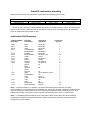
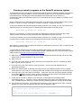
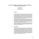
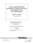
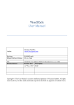
Sweet32 Minimal-RISC User Manual
By Valentin Angelovski (c) 2014-2015
Release date: 28th-February-2015
(Preliminary) Release version: 0.95
What is Sweet32?
Sweet32 is best described as a ‘no-frills’ 32bit minimal-RISC microprocessor core with a load/store
register architecture with a simple bus interface.
Originally started as a means towards learning VHDL, Sweet32 has evolved into a reasonably low-gatecount CPU that can be used for learning or even real-world applications. Typical Sweet32 logic utilization,
on the Lattice MachXO2 FPGA (for example), is 842 LUT4 elements in a standard configuration and
area-optimized form. Sweet32 was written in VHDL and is released under LGPL 2.1
Sweet32 Architecture Summary
•
•
•
•
•
•
•
•
•
•
•
16x32-bit General Purpose CPU registers
Little-endian architecture
27 Instructions, focussed mainly on 32bit and 16bit data processing
16x16-bit multiplier standard, with optional 32x32-bit multiplier support
Conditional branch/compare opcodes, with no Status flags register
Completely register-based CPU, with no hardware stack pointer
Unaligned data access support for 8 and 16bit data. (32bit data must be 16bit word-aligned)
Single-cycle external IRQ channel
32bit internal data-path and 16bit Data external bus
Basic Trace/debug interrupt support included
Simple to implement and/or emulate!
Sweet32 CPU Block Diagram
Program
Counter
Reg Z
Reg X
ALU
Reg Y
Fast IRQ
and trace
support
CPU Reset
Logic
32bit x 16
General Purpose
register file
D31-D0
32bit to
16bit bus
converter
A31-A0
System timer
D15-D0
mem_read_o
mem_write_o
Instruction Decoder
RAM/ROM
D15-D0
Bus_wait
IRQ0
rst (reset)
clk1 (BIU_clk/4)
Peripheral
Bus
Interface
Unit
ADC/PWM
To GPIO etc.
Interrupt
reset
clock
CPU Core Registers Description
Sweet32 is composed of the following core registers:
R0-R15
General Purpose Registers
(Direct Read/Write)
These registers are all directly accessible by the programmer for the purposes of logic and arithmetic
processes, as well as temporary variable/constant/pointer storage. It is the responsibility of the
programmer to initialize these registers upon power-up as they are not cleared upon reset and will
contain undefined values.
PC
Program Counter
(Direct Read/Indirect Write)
This register is used to store the address of the current program instruction being pointed to. Please note
that as Sweet32 instructions are mostly 16-bits wide, every program counter increment represents one
16-bit instruction or data word currently being accessed. Consequently, all Sweet32 programs must be
16-bit word-aligned. Upon Sweet32 reset, program execution begins from location zero (i.e. 0x00000000)
Program counter is directly readable only via the GETPC instruction and can be indirectly written to using
the LJMP instruction.
IRQ0VEC
IRQ0 Interrupt vector address
(Direct Write-only)
This register stores the absolute 32-bit address of the user IRQ0 handler routine. Upon the receipt of a
valid IRQ event (i.e. logic high or ‘1’), the program counter register is preserved and then the new value
stored in this register is loaded. This causes the Program counter to effectively jump straight to the
specified start address of the IRQ0 handler for processing.
IRQ0_RTN
IRQ0 Interrupt return address
(Not accessible)
This register is used internally by Sweet32 to store the return address of the IRQ interrupt cycle. When
the IRQ handler routine has ended with the RETI instruction, the program counter is then re-loaded with
the value previously saved in this register and main program execution continues as per normal.
TRACE_RTN
Trace Interrupt return address
(Direct Read-only)
This register is used by Sweet32 to store the return address of the Trace/Debug interrupt cycle. When the
trace/debug routine has ended with the RETT instruction, the program counter is then re-loaded with the
value previously saved in this register and (if the trace interrupt is no longer enabled) main program
execution then continues. This register is accessible to the programmer using the GETTR instruction.
CW
CPU Control word
(Direct Write-only)
This register controls the external event handling capabilities of the Sweet32 Microprocessor. By setting
the appropriate bit location to ‘1’ the specified function is enabled, while clearing the bit disables the
function. Upon reset, the control word register is completely set to zero (ie all external event handlers are
disabled).
Control Word (CW) Register usage:
Bit 31 = trace/debug
enable
XR
Bits 30 to 1 = Reserved for future use
Bit 0 = Interrupt IRQ0
enable
**OPTIONAL** 32x32 Multiplier upper 32-bit result (Read-only)
When implemented (normally it is NOT present in the standard Swee32 CPU config.), this register holds
the upper 32bit result of an extended 64bit math operation (i.e. 32x32bit multiply). This register is
accessible only using the (also optional) ‘GETXM’ opcode and must be executed immediately after a
MUL opcode.
Sweet32 instruction encoding
Most Sweet32 opcodes are fixed 16-bit* organized in the following typical format:
Bits 15 downto 12
Opcode select
Sweet32 Instruction 16-bit word format
Bits 11 downto 08
Bits 7 downto 4
RegY_select
RegZ_select
Bits 3 downto 0
RegX_select
* = Some opcodes, like LDD, LDW and MJMP will require an additional word or two to fully encode their
data (see next section). Note also that all instructions must be 16-bit word-aligned and all 32-bit data
must be represented in big-endian format
Instruction Set Summary:
Topmost-Nibble
Encoding:
Sweet32
Instruction:
Instruction
operands:
0000:
0001:
0010:
0011:
“
0100:
0101:
0110:
0111:
1000:
1001:
1010:
"
"
"
"
"
1011:
1100:
"
"
1101:
"
1110:
1111:
AND
ADD
XOR
TST(SNZ/SZ)
BIT(SNZ/SZ)
SUBSLT
MUL/GETMX**
SJMP
LDB
MJMP
GETPC
LDW/D
SETIV
RETI
SETCW
RETT
GETTR
INCS
SWAP(B/W)
NOT
LJMP
LSR
ASR
MOV(W/D)
MOV(W/D/SW)
Rz,Rx,Ry
Rz,Rx,Ry
Rz,Rx,Ry
Rx,Ry
Rx,#imm5
Rz,Ry,Rx
Rz,Rx,Ry / Rz
#rel12
Rz,#imm8
#rel28
Rz, #imm8
Rz,#imm16
Rx
Rx
Rz
Rz,Rx,#signed_imm4
Rx
Ry,Rx
abs32 Rx
Rx
Rx
[Ry],Rx
Ry,[Rx]
Instruction
Cycles*:
1
1
1
1
1
1
1/2
1
1
2
1
3/4
1
1
1
1
1
1
1
1
1
1
1
3/4
4/5
Note: * = While Sweet32 is 1T capable, it is heavily dependent on Bus Interface Unit (BIU)
implementation for best performance. As supplied with, this project, the BIU is greatly simplified in that it
uses no pipelining or multi-phase clocks, but it does feed the Sweet32 CPU a divide-by-3 clock, thus
making it technically a 3T system. Future Sweet32 releases may also include a 1T BIU variant.
Note: **= GETMX opcode is designed to be used with the MUL opcode when the 32x32 multiplier
configuration is enabled in the Sweet32 VHDL module, please refer to the MUL opcode instruction
description for further details.
Sweet32 Instruction Set Description
"AND Rz, Rx, Ry" Boolean AND
Takes the logical AND of Rx, Ry and stores the result into Rz
Encoding = 0000 + Ry_addr + Rz_addr + Rx_addr
"ADD Rz, Rx, Ry" Unsigned addition
Performs a 32bit unsigned binary addition of Rx, Ry and stores the result into Rz.
Encoding = 0001 + Ry_addr + Rz_addr + Rx_addr
"XOR Rz, Rx, Ry" Boolean XOR
Takes the logical AND of Rx, Ry and stores the result into Rz
Encoding = 0010 + Ry_addr + Rz_addr + Rx_addr
"TSTSZ Ra, Rb" Boolean AND test and skip if zero
Performs a logical AND of Rx, Ry and skips the next program location if the result was zero. Result is
NOT saved but is discarded.
Encoding = 0011 + Rx_addr + 0100 + Ry_addr
"TSTSNZ Ra, Rb" Boolean AND test and skip if NOT zero
Performs a logical AND of Rx, Ry and skips the next program location if the result was NOT zero. Result
is NOT saved but is discarded.
Encoding = 0011 + Rx_addr + 0000 + Ry_addr
"BITSZ Ra, #imm5" Boolean single-bit AND test and skip if zero
Performs a logical AND on a desired bit within Rx and skips the next program location if the result was
zero. Result is NOT saved but is discarded.
Encoding = 0011 + Rx_addr + 1100 + #imm5 (selects Rx register bit to test from 0 to 31)
"BITSNZ Ra, #imm5" Boolean single-bit AND test and skip if NOT zero
Performs a logical AND on a desired bit within Rx and skips the next program location if the result was
NOT zero. Result is NOT saved but is discarded.
Encoding = 0011 + Rx_addr + 1000 + #imm5 (selects Rx register bit to test from 0 to 31)
"SUBSLT Rz, Ry, Rx" Unsigned subtraction and skip if Ry < Rx
Performs an unsigned subtraction ie. Ry – Rx and stores the result in Rz. If the result was less than zero
(i.e. negative) the next program location is skipped.
Encoding = 0100 + Ry_addr + Rz_addr + Rx_addr
Sweet32 Instruction Set Description (continued)
"MUL Rz, Rx, Ry" Unsigned 16x16bit Multiply (includes optional 32x32bit multiply information)
Performs an unsigned 16x16-bit multiply of Rx, Ry and stores the 32-bit result into Rz
Encoding = 0101 + Ry_addr + Rz_addr + Rx_addr
Operation in the optional 32x32 unsigned multiply mode: In addition, there is an option within the
Sweet32 HDL source to enable the 32x32-bit extended unsigned multiply function, which produces a
64bit result that is stored in both Rz (lower 32bit) and XR (upper 32bit) registers respectively.
Warning: If performing a 32x32 multiply and the upper 32bit result is required, ‘GETMX’ opcode must be
executed immediately after the MUL instruction. This is because the result data from the execution of a
MUL op is only guaranteed to be valid for one cycle after the MUL execution.
"SJMP #rel12" Short relative jump
Performs an unconditional relative jump to the new location specified by PC = PC + #rel12
Encoding = 0110 + #rel12
"LJMP @Rx" Long Absolute and indirect Jump
Performs an unconditional absolute jump to the new location specified by PC = Rx
Encoding = 1100 + 0011 + 0000 + Rx_addr
"MJMP #rel28" Medium relative Jump
Performs an unconditional relative jump to the new location specified by PC = PC + #rel28
Encoding (1st-word) = 1000 + #rel28 (uppermost 12-bits)
Encoding (2nd-word) = #rel28 (lower 16-bits)
"GETPC Rz, #imm8 " Get current program counter value and add offset
Fetches the current program counter (PC) value and adds an immediate 8-bit unsigned offset to it i.e: Rz
= current pc + #imm8
Encoding: 1001 + #imm8_upper4 + Rz_addr + #imm8_lower4
"INCS Rz,Rx,#signed_imm4" increment CPU reg by signed immediate 4-bit word
Performs addition of a signed 4-bit immediate value to Rx and stores the result in Rz
Encoding = 1010 + Rx_addr + Rz_addr + #signed_rel4
"LDW Rz,#imm16" Load immediate 16-bit word (## Currently used as LDW Rz,#imm16)
Loads a 16-bit immediate data constant into the lower-half of CPU register Rz. Upper word portion of the
destination CPU register is cleared i.e. set to “0x0000”
Encoding (1st-word) = 1011 + 0000 + Rz_addr + 0000
Encoding (2nd-word) = #immediate 16-bit word
Sweet32 Instruction Set Description (continued)
"LDD Rz,#imm32" Load immediate 32-bit word
Loads a 32-bit immediate data constant into CPU register Rz.
Encoding (1st-word) = 1011 + 0001 + Rz_addr + 0000
Encoding (2nd-word) = #immediate 32-bit word (upper 16-bits)
Encoding (3rd-word) = #immediate 32-bit word (lower 16-bits)
"SETIV Rx" Set IRQ0 Interrupt Vector Address (32bit)
Takes the 32bit value stored in Rx and copies it to the IRQ0VEC register
Encoding = 1011 + 0010 + 0000 + Rx_addr
"RETI" Return from IRQ0 Interrupt Routine
Loads the PC reg with the contents of the IRQ0RTN register
Note: IRQ must be enabled by setting bit 0 of the control word (CW) register
Encoding = 1011 + 0011 + 0000 + 0000
"RETT" Return from Trace/Debug Routine
Loads the PC reg with the address of the next program instruction to trace/debug
Note: Trace/Debug must be enabled by setting bit 31 of the control word (CW) register
Encoding = 1011 + 0101 + 0000 + 0000
"GETMX Rz" Get upper 32bit result of Extended Math operation
Fetches the value stored in the Sweet32’s XR register and stores it in Rz. GETMX is normally used in
conjunction with the MUL opcode, when the 32x32bit extended multiply option is implemented.
Encoding = 1011 + 0110 + Rz_addr + 0000
"GETTR Rz" Get Trace Return Address
When the trace/debug hardware support is enabled, GETTR allows a trace event handler to access the
address of the next main program instruction to be executed.
Encoding = 1011 + 0111 + Rz_addr + 0000
"SETCW Rx" Set CPU control word register
Takes the 32bit value stored in Rx and copies it to the CW (Control Word) register
Encoding = 1011 + 0100 + Rz_addr + 0000
"SWAPB Rz,Rx" Swap bytes in lower CPU reg word
Performs a data swap of the two bytes in the lower 16-bit portion of a specified CPU register
Encoding = 1100 + 0000 + Rz_addr + Rx_addr
"SWAPW Rz,Rx" Swap words in CPU reg
Performs a data swap of the lower and upper words in a specified CPU register
Encoding = 1100 + 0001 + Rz_addr + Rx_addr
Sweet32 Instruction Set Description (continued)
"LSR Rz,Rx" Logical Shift Right
Performs a logical right shift on the data of a specified CPU register by 1 bit. Result is shifted one bit to
the right with the most significant bit is cleared to ‘0’. As there is no carry flag within Sweet32 the former
least significant bit is discarded. Use BITSNZ to test the least significant bit value.
Encoding = 1101 + 0000 + Rz_addr + Rx_addr
"ASR Rz,Rx" Arithmetic Shift Right
Performs a logical right shift on the data of a specified CPU register by 1 bit. Result is shifted one bit to
the right with the most significant bit set to equal bit 30, thus preserving the sign of the shifted value. As
there is no carry flag within Sweet32 the former least significant bit is discarded. Use BITSNZ to test the
least significant bit value.
Encoding = 1101 + 0001 + Rz_addr + Rx_addr
"NOT Rz,Rx" Compliment register
Performs an inversion operation on the 32bit value stored in Rx and passes the result on to Rz.
Encoding = 1101 + 0010 + Rz_addr + Rx_addr
"MOVW [Ry],Rx" Move 16-bit data from CPU register to Memory
Performs an indirect 16-bit data move from CPU register Rx to the memory location referred by Ry
Encoding = 1110 + Ry_addr + 0000 + Rx_addr
"MOVD [Ry],Rx" Move 32-bit data from CPU register to Memory
Performs an indirect 32-bit data move from CPU register Rx to the memory location referred by Ry
Encoding = 1110 + Ry_addr + 0001 + Rx_addr
"MOVW Ry,[Rx]" Move 16-bit data from Memory to CPU Register
Performs an indirect 16-bit data move to CPU register Ry, from the memory location referred by Rx
Encoding = 1111 + 0000 + Ry_addr + Rx_addr
"MOVD Ry,[Rx]" Move 32-bit data from Memory to CPU Register
Performs an absolute 32-bit data move to CPU register Ry, from the memory location referred by Rx
Encoding = 1111 + 0001 + Ry_addr + Rx_addr
"MOVSW Ry,[Rx]" Move 16-bit data and sign-extend to 32bits from Memory to CPU Register
Performs an indirect 16-bit data move to CPU register Ry, from the memory location referred by Rx. Most
significant bit is copied sixteen times in the uppermost word of the destination CPU register, thus sign
extending the word to 32bits.
Encoding = 1111 + 0000 + Ry_addr + Rx_addr
Additional Instructions (assembler generated pseudo-ops):
The following additional (implied) instructions are available via the Sweet32 assembler (applies to
assembler versions 1.00 and up). These are:
"MOV Rz,Rx " Move 32-bit data from Rx to Rz
Derived from the INCS opcode. Takes the value of CPU register Rx and stores the result in Rz
Encoding = 1010 + Rx_addr + Rz_addr + 0000
"NOP " No operation
Derived from the AND R0,R0,R0 opcode. Effectively does nothing for one CPU cycle
Encoding = 0000 + 0000 + 0000 + 0000
IRQ External Interrupt Behaviour (typical interrupt sequence)
•
•
•
•
•
•
IRQ0 is enabled by setting bit-0 of the CPU control word to '1'
The IRQ0 signal line is level-triggered with a logic '1'
When an IRQ0 trigger is detected, the current Program Counter (PC) value is saved to the
IRQ0RTN register. Then the PC is loaded with the interrupt vector address value as stored in the
IRQ0VEC register
The code pointed to by IRQVEC is now executed.
When the user IRQ INT handler routine has completed it’s task, the interrupt cycle must be
terminated by the issuing of a RETI opcode. This causes the PC register to be restored with the
address value previously saved in IRQ0RTN
Normal program execution resumes.
Trace/Debug Interrupt Behaviour
•
•
•
•
•
•
•
•
Trace/Debug interrupt, when enabled, branches off to a fixed address in Sweet32 RAM upon
execution of one main program instruction.
Trace/debug is enabled by setting bit-31 of the CPU control word to logic '1'
Trace interrupt has priority over the fast IRQ channel, allowing interrupt handler code to be
traceable as well.
The address of the next opcode to be executed can be obtained using the GETTR instruction.
After the execution of the next opcode, the program counter is loaded with the fixed trace handler
address of 0x00000002. Note the debug handler MUST be located here (if present) and cannot
be moved elsewhere in Sweet32’s program address space.
When the user trace/debug handler routine has completed it’s task, the interrupt cycle must be
terminated by the issuing of a RETT opcode. This causes the PC register to be restored with the
address value previously saved in TRACE_RTN
Normal program execution of the next opcode occurs, before another trace event is triggered.
Trace events may be stopped at any time by clearing bit-31 of the Sweet32 Control Word (CW).
Sweet32 Control Signalling
Swwet32 CPU's Interface consists of the following bus control signals:
data_i
= 16 Data input lines
data_o
= 16 Data output lines
addr_o
= 32 Address output lines
mem_write_o
= Memory write output line (mem write access request = logic level ‘1’)
mem_read_o
= Memory read output line (mem read access request = logic level ‘1’)
IRQ0
= Fast Interrupt Request input line (triggered = logic level ‘1’)
bus_wait
= bus wait input line (All CPU activity freezes = logic level ‘1’)
clk1
= CPU clock input
rst
= System reset input line (Reset active = ’0’)
With the exception of system reset (rst), all signals are processed with the rising edge of the CPU clock
(clk1)
Sweet32 CPU Timing diagrams
Memory read waveform: CPU Instruction fetch/execute of opcode “LDD R3, #0x00000100” Because
LDD is a multi-word (3 x 16bit word) opcode, Sweet32 will fetch the opcode again to complete the
execution of the instruction (hence why LDD takes 4 CPU cycles instead of 3).
Memory write waveform: CPU Instruction fetch/execute of opcode MOVW @R1,R2
Because MOVW is a single-word opcode, Sweet32 does not fetch the opcode again at the completion of
the instruction cycle. Assume register R1 = 0x10000000, while R2 = 56781234
About the Bus Interface Unit (BIU)
Sweet32 is not intended to be used on it’s own (of course), but in conjunction with a Bus Interface Unit
(BIU) which allows the inclusion of external HDL peripherals. The BIU be in the form of a simple
peripheral address decoder with some timing glue logic to more complex ones that are compatible to a
common interface standard i.e wishbone. Only the former solution is implemented and discussed here.
Sweet32’s own BIU acts as a bridge to many standard peripheral devices, including those that require a
faster or slower clock rate than that of the CPU itself to function properly.
The BIU provided for use with the Sweet32 CPU performs the following functions (Please refer to
“Sweet32_BIU.vhd” for more details):
•
•
•
Clock divide-by-4 counter. This means a BIU clock of 100MHz will generate a CPU clock of
approximately 25MHz with a 50% duty cycle
Provides a synchronized reset signal to the Sweet32 after the BIU itself has been reset
A bus-transaction FSM for processing of memory reads/writes between the CPU and selected
peripherals. The FSM consists of the following three states repeated indefinitely after reset:
State 1:
State 2:
Set Sweet32 CPU clock to ‘0’. Latch data from an addressed peripheral for reading
or writing by Sweet32 etc.
Hold Sweet32 CPU clock low
State 3:
Set Sweet32 CPU clock to ‘1’ and hold high for one state only
State 4:
Hold Sweet32 CPU clock high
Typical application: Sweet32 minimum-system example
To help the user get started with Sweet32, there is a minimum-system or embedded microcontroller
setup included in the archive with this document. Following is a block diagram, showing all of the
connected peripherals and their associated VHDL modules (Note: Apart from the CPU, CRTC and
system timer, all other system peripherals are clocked at 100MHz by the BIU):
32Mbyte
(16Mbytes x 16)
SDRAM interface
VGA 80x25
character text
controller
PS/2
Keyboard
interface
Future
expansion
options
BUS INTERFACE UNIT (BIU)
clocked at 100MHz
IRQ0
Sweet32_BIU.vhd
25MHz
clock
25MHz
clock
Sweet32 CPU
16bit TIMER
11bit ADC
Sweet32_v1_core.vhd
regfile_32x16.vhd
Sweet32_BIU.vhd
Simple_ADC.vhd
4bit
OUTPUT PORT
Sweet32_BIU.vhd
16KByte ROM/RAM
UART
(Containing serial boot loader)
Sweet32_SRAM.vhd
simple_UART.vhd
11bit PWM
simple_PWM.vhd
Sweet32 minimum system Peripheral Address Map
Following table provides a detailed map of all system ports in the Sweet32 minimum system. Note: Assume
all control flags to be active when set to logic ‘1’ Also, “CPU D7-D0” indicates CPU Data bus lines 7 to 0 etc.
Note: * = Expansion peripherals added to the Sweet32 minimum system design. These may be removed as
desired.
Peripheral Description
Port
Description
Port address
16KByte ROM / RAM
Embedded
and/or boot
ROM + RAM
0x00000000 to
0x00003FFF
Initialised with a Sweet32 serial boot loader ROM program. Can also be
used as System RAM and is writeable
*Expanded system RAM
Addressable
memory
0x10000000 to
0x6FFFFFFF
Typical DRAM setting for Sweet32 in an expanded system configuration
is (for inclusion into existing FPGA designs) 32Mbytes RAM.
*80x25 character VGA CRTC
4KByte character buffer area
Read / write
buffer area
0x20000000 to
0x20000FFF
4K Character mapping identical to IBM CGA 80x25 standard i.e.
character byte followed by a color attribute byte at the next buffer
address – which is repeated for all 2000 on-screen text characters
*80x25 character VGA CRTC
2KByte font bitmap area
Read / write
buffer area
0x30000000 to
0x300007FF
User-programmable text font bitmap lookup RAM. Code page 437 font is
normally loaded into this area by default upon boot-up
Simple 8n1 UART
with user-variable baud rate.
Default baud rate upon reset is
115.2KBaud. Typical settings are:
115.2K 8n1
Higher baud rates also possible
DATA register
0x70000000
Set 16bit baud
rate timer
0x70000002
undefined
Timer reload value <= CPU D15D0
Reset character
received flag
0x70000004
undefined
RX receive flag <= ‘0’
Set 16bit timer
count
0x70000020
undefined
Timer reload value <= CPU D15D0
Control register
0x70000022
CPU D0 <= Timer overflow flag
Timer overflow flag <= CPU D1
Timer enable <= CPU D0
4bit output port
0x70000030
undefined
4bit output <= CPU D3-D0
Simple 16bit Timer
Counts upward until overflow.
Upon overflow, timer count is
reloaded with a user-settable
value and an overflow flag is set.
Overflow flag is wired to Sweet32
IRQ0. Timer operation can be
paused or stopped by setting the
Timer enable flag to ‘1’
User GPIO
(output port only)
0x70000038
*PS/2 Keyboard port
Provides a bidirectional PS/2 port
interface for Sweet32
Analog-to-digital converter
Configured as free-running
converter. Uses sigma-delta
method and has 11bit resolution
Pulse width modulation output
Resolution is 11bits. Implemented
using a binary rate multiplier
*80x25 character VGA CRTC
Control register mapping
Port read behaviour
CPU D7-D0 <= RX data byte
CPU D8 <= TX buffer empty
CPU D9 <= Character received
CPU D11 <= PS/2 RX ‘data
received’ flag
CPU D10 <= PS/2 TX ready
CPU D7-D0 <= RX data register
Port write behaviour
TX buffer <= CPU D7-D0
TX data register <= CPU D7-D0
(Note: A write to this register
initiates a sending of the passed
data byte to the PS/2 client (ie
keyboard/mouse)
0x7000003A
undefined
Resets the PS/2 RX ‘data
received’ flag,
Data input
register
0x70000040
CPU D10-D0 <= ADC sample
no effect
Data output
register
0x70000040
undefined
PWM output <= CPU D10-D0
General CRTC
configuration
0x70000050
Cursor X
position
0x70000052
Cursor X-position update/status
CPU D7-D0
Cursor Y
position
0x70000054
Cursor Y-position update/status
CPU D7-D0
cursor_blink_on <=> CPU D5
cursor_enable <=> CPU D6
vga_enable <=> CPU D7
Running example programs on the Sweet32 minimum system
As mentioned over the previous page, the Sweet32 minimum system is capable of loading user programs
into ROM via the serial port (UART). In terms of toolchain support, there is an assembler tool called
“Sweet32asm.EXE” (including associated FreeBASIC sourcecode) that can be found in the
\firmware\asm folder of the Sweet32 project archive. Assembler files may be created or modified in a text
or source editor.
Note the assembler tool is somewhat limited and does not include macro support, though it does get the
job done. ☺ Work is currently underway to re-target an existing c compiler for Sweet32.
To use the assembler tool with the example assembly programs (or to create your own) for upload to the
Sweet32 system via serial, simply run the following from the windows command prompt:
Sweet32asm
myexample.asm
myapp.swe
When the .swe extension is used for the output file, Sweet32asm produces a binary file with a 32bit
‘header’ (which is basically a raw program size value) appended to the start of the file.
To use the assembler tool with the example assembly programs (or to create your own) for inclusion into
your Sweet32 boot ROM, simply run the following from the windows command prompt:
Sweet32asm
myexample.asm
myapp.vhd
Note when the .vhd extension is used for the output file, Sweet32asm produces a VHDL-compliant format
of the assembled binary output
To upload files to Sweet32 using the serial boot loader ROM program, you will need a serial terminal
program running on your host PC. In the following example, I will describe how to do this using a program
called TeraTerm (http://en.sourceforge.jp/projects/ttssh2/) .
1.) Make sure your FPGA-board is loaded with a valid Sweet32 project bit-file and that you have a USBbased serial connection between it and your host PC
2.) Start TeraTerm
3.) In the top menu, goto “Setup” and then “Serial Port” and configure the port for 115200 Baud, 8-bits
data, no parity and one stop bit.
4.) In the top menu, goto “File” and then “New Connection..” and connect with Sweet32 via the
appropriate COM port.
5.) Reset your Sweet32 CPU, by pressing user button #2 on your FleaFPGA board or on any suitable
FPGA platform of your choice. You will be greeted with a loader boot message in the terminal window.
6.) In the top menu, goto “File” and then “Send file..”. Select the “hello.swe” program example to upload
to the FPGA and make sure the ‘binary’ option in the bottom left hand corner is selected! Click open
to continue, this causes TeraTerm to send the file to Sweet32
7.) As the data is received by Sweet32, ever two bytes received (less the file header) will be
acknowledged with a “.” character. Once the file transmission has ended, the loader will then print a
“Go!” message and then attempt to execute the newly-loaded program from location 0x100 in RAM.
8.) If the upload was successful, you should see the following on your Terminal screen. Note: The dots
indicate one byte of data sent and echoed back from the Sweet32 loader.
*** Sweet32 serial program loader ***
>..........................................................
Go!
Hello World! From Sweet32 DRAM test app!!! RRAAWWHHH :-D
Sweet32 executable binary file (.SWE) - Version 2.0 format
Sweet32 executable binary file consists of the following data formatting:
Header formatting:
"UUSw32v2"
0xAAAAAAAA
0xLLLLLLLL
- Constant 8-character ASCII header with architecture & version
- 32-bit little-endian (MSB first) fixed load address (or 0 for variable)
- 32-bit little-endian (MSB first) word program length
Payload data:
<0xL big-endian 16-bit words of code/data>
Footer formatting:
"Nd"
0xCCCC
- Constant 2-character ASCII footer e'Nd' indicator
- 16-bit CRC checksum
More detailed overview of the proposed .SWE (Sweet32 loader file) format, including
memory offsets etc:
Offset 0:
8 byte ASCII string: 0x55 0x55 0x53 0x77 0x33 0x32 0x76 0x32 = "UUSw32v2"
The "UU"'s are there to assist with auto-baud rate, "Sw32" for architecture
and "v2" for format version 2.
Offset 8:
4 byte little-endian load address: 0xAAAAAAAA
(E.g., address 0x01020304: 0x01 0x02 0x03 0x04)
A zero address indicates position independent code where the loader will determine
load address at run-time.
Offset 12:
4 byte little-endian length in 16-bit words: 0xLLLLLLLL
(E.g., length 0x01020304: 0x01 0x02 0x03 0x04)
<Sweet32 binary executable data - body of "Length" 16-bit big-endian words>
Offset 16 + (Length*2):
2 byte ASCII string: 0x4E 0x64 = "Nd"
End indicator
Offset 18 + (Length*2):
16-bit CRC checksum: 0xCCCC
Sweet32 Assembly coding examples
Following is a tiny collection of typical Sweet32 assembly examples. Further coding examples may be
found in the \firmware\asm folder of the Sweet32 project archive on either www.opencores.org or
www.fleasystems.com
1.) Subroutine call example #1: Call with return address stored in R15 (3 CPU cycles to execute):
main code:
GETPC
R15, #2
; Get current program counter (PC) value and add return offset
MJMP
mysub
; Perform subroutine call
; <-- Code resumes execution here after Sub return
mysub:
; <-- User subroutine code goes here
LJMP
R15
; Perform subroutine return
2.) Subroutine call example #2: Using R15 as a stack pointer (7 CPU cycles to execute):
main code:
GETPC
R14, #5
; Get current program counter (PC) value and add return offset
MOVD
@R15,R14
; Save PC
INCS
R15,R15,#+2
; Increment virtual stack pointer
MJMP
mysub
; Perform subroutine call
; <-- Code resumes execution here after Sub return
mysub:
; <-- User subroutine code goes here
INCS
R15,R15,#-2
MOVD
R14,@R15
LJMP
R14
; Decrement virtual stack pointer
; Get previously stored address
; Perform subroutine return
3.) Signed 16x16bit multiply routine (takes between 5 and 11 CPU cycles to execute):
;Assume: R0 = Signed 32bit Result,
;
R1 = Signed 16bit ‘X’ value
;
R2 = Signed 16bit ‘Y’ value
signed_multiply:
XOR
BITSNZ
SJMP
BITSNZ
SJMP
NOT
INCS
Do_multiply:
MUL
INCS
NOT
LJMP
makeY_pos:
NOT
INCS
SJMP
Signs_equal:
MUL
LJMP
R0,R1,R2
R0,#15
signs_equal
R1,#15
makeY_pos
R1,R1
R1,R1,#1
; Test if X is negative
; X is positive, Y must be negative
; Make X positive if currently negative
;
R0,R1,R2
R0,R0,#-1
R0,R0
R15
;
; Make result negative
;
; Subroutine return
R2,R2
R2,R2,#1
Do_multiply
; Make Y positive
;
; Go perform our multiply
R0,R1,R2
R15
; Result will be a positive number
; Test if X and Y are either both positive or both negative
Sweet32 Assembly coding examples (Continued)
4.) Unsigned 16bit / 16bit software divide routine (takes approx. 134 CPU cycles max. to execute):
;*** Sweet32 unsigned 16/16 division routine ***
; Registers R0-R6 are used by this routine (R6 being a temporary register)
; R0 = Remainder reg, R1 = Quotient reg, R2 = Divisor reg, R3 = Dividend reg,
; R4 = # of bits to divide by + 1, R5 = quotient bitwise-OR mask value,
; R6 = Temp reg
; Total calculation time = 6 + 128 cycles = 134 cycles total (maximum)
Divide_U1616:
LDD
LDB
LDB
R5,#0x10000
R4,#17
R0,#0x0
; Mask value for quotient bitwise OR-add
; Number of bits to divide by + 1
; Clear Quotient reg
; Actual division routine begins here:
SWAPW
R2,R2
; Prepare Divisor (ie Divisor << 16)
Division_loop:
SUBSLT
SJMP
R6,R2,R3
doesnt_go
; compare (subtract) shifted divisor with dividend
; shifted divisor > dividned
does_go:
INCS
ADD
LSR
LSR
INCS
TSTSNZ
SJMP
SJMP
R3,R6,#0
R0,R0,R5
R2,R2
R5,R5
R4,R4,#-1
R4,R4
Division_done
Division_loop
doesnt_go:
LSR
LSR
INCS
TSTSZ
SJMP
R2,R2
R5,R5
R4,R4,#-1
R4,R4
Division_loop
; Set the appropriate bit of the quotient
; Shift the divisor down by 1
; Shift the quotient bitmask down by 1
; Decrement bit count
; Have we reached the end of our divide routine?
; Shift the divisor down by 1
; Shift the quotient bitmask down by 1
; Decrement bit count
; Have we reached the end of our divide routine?
Division_done:
INCS
R1,R3,#0
; Move to result reg
LJMP
R14
; exit routine
; ************* End routine ****************
Sweet32 CPU Development history
Version 1.00
28/02/2015
Major update to convert Sweet32 into little endian
Format for easier C compiler/toolchain creation.
BITSZ and TSTSZ opcodes and GETPC opcodes
revised or added. Sweet32 minimum system
architecture expanded upon and updated.
Version 0.90
28/11/2014
Minor update to reflect improvements in the Sweet32
Assembler and to fully document the Sweet32 Loader
File format (.SWE file extension).
Version 0.80
18/11/2014
Added LDB, ADD and SUBSLT opcodes.
Removed ADDSNC and OR opcodes.
Assigned new opcode encoding to LJMP
Removed NEG opcode, replaced with NOT
Serial loader, assembler and code examples all revised to
reflect the updated Sweet32 instruction set.
Version 0.71
17/11/2014
Included information on updated serial Boot-loader
Unsigned software divide example included.
Version 0.70
13/11/2014
Added NEG, GETTR and (optional) GETMX opcodes
32x32bit extended math now available as an option.
Version 0.60
4/11/2014
Added ASR, BITSNZ and MOVSW opcodes
Modified LSRSC to become LSR opcode.
Version 0.40
21/10/2014
Added simple trace/debug support
Reduced the BIU bus states from 4 down to 3
Version 0.30
17/09/2014
Added MOVD, modified MOVW ops
Version 0.21
10/09/2014
Added fast IRQ support
Version 0.10
1/09/2014
Initial pre-release
Legal Disclaimer
This document is provided as-is and with strictly no warranties implied. While every effort is made to
ensure the information presented is accurate I, Valentin Angelovski, make no such guarantee. I also
reserve the right to update this document without prior notice. This document is the copyright of
Valentin Angelovski. All trademarked product names listed herein belong to their respective
trademark owners.