1
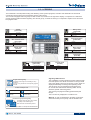
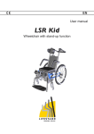
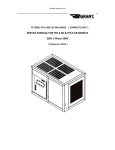
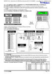
TP8-28 - TP8-28 GSM
Expandable serial alarm systems
User quick guide
Release:
FW version:
Control panel versions:
Programming SW version:
Update:
Language:
1.0
0.2.00
TP8-28 - TP8-28 GSM
4.45
12/2013
English
CONFORMITY
The present equipment is in compliance with the essential requirements and other relevant provisions of the
R&TTE 1999/05/EC directive. The equipment is also in compliance with the standard EN 50131-1.
The declaration of conformity is available on the website: www.tecnoalarm.com.
The product features can be subject to change without notice. Unauthorized reproduction or distribution of this manual, or any portion
of it, on any device and in any form, is prohibited. The contents of this manual may be subject to change without notice.
TP8-28 - TP8-28 GSM
INDEX
1 - CONSOLES
1-1
LCD300/S
5
1-2
LCDPROX1
7
2 - ARMING WITH CODE
2-1
Arming
11
2-2
Disarming
11
2-3
Direct arming
12
2-4
Direct disarming
12
2-5
Arming with exclusion of the open zones
13
2-6
Hold-up alarm activation
13
2-7
Panic alarm activation
14
2-8
Consultation of the stored alarms
14
2-9
Consultation of the event log
14
TP8-28 - TP8-28 GSM
3
4
TP8-28 - TP8-28 GSM
1 - CONSOLES
1-1 - LCD300/S
The LCD300/S console permits arming and disarming of the system’s programs, activation and deactivation of the remote controls
and gives access to the programming menus of the system.
The console is equipped with two groups of LED: the first one, below the display, is composed of 6 LED that provides general trouble
and status signaling. The second group, below the keys, is composed of 15 pairs of LED and views the program states and alarms.
Trouble
(yellow LED)
Off
Blinking quickly
Blinking slowly
On
CM
No trouble
Active trouble
Active GSM trouble
Stored trouble
Tue
10 JAN 12
Work.
13:46
+
Off
Blinking
On
Off
Blinking
On
Console not in use
Console in use
Tamper alarm
(red LED)
Off
Blinking slowly
On
Battery OK
Low battery
Battery fault
No alarm
Active alarm
Stored alarm
Mains voltage
(green LED)
Off
On
No alarm
Active alarm
Stored alarm
Program status
(yellow LED)
Off
Blinking quickly
Blinking slowly
On
Battery status
(yellow LED)
Power failure alarm
(yellow LED)
CM - Command mode
(green LED)
Off
On
-
Program disarmed
Arming phase
Program partset
Program armed
Mains voltage absent
Mains voltage present
Program alarm
(red LED)
Off
Blinking
On
No alarm
Alarm active
Stored alarm
Signaling LED
Trouble LED
The system constantly controls its functioning. Any trouble is immediately signaled. In case of active trouble the LED
is blinking, at the end of the alarm, it is switched on permanently to signal that the alarm has been stored. The stored
alarm signal continues until it is cancelled with the appropriated procedure. The troubles are also stored into the
event buffer of the system.
Blinking quickly: Trouble of the system’s GSM module
Blinking slowly: General trouble of the system.
CM
CM LED
The CM LED (command mode) is lit as soon as the user starts typing on the keys. It is lit during the entire access
time and during 10 seconds after the last keystroke. When the LED is switched off, the user must enter the access
code again to have access to the console.
TP8-28 - TP8-28 GSM
5
Tamper alarm LED
The LED signals the tamper alarms of the system. The system’s anti-tamper protection is always active and is
independent from the program status.
Off: No tamper alarm
Blinking: Active tamper alarm
On: Stored alarm. The stored alarm signal continues until it is cancelled with the appropriated procedure
-
Battery status LED
The LED signals the status of the system’s battery.
Off - Battery OK
Blinking – Low battery
On - Battery fault, i.e. the battery is no longer able to support the system
+
Power failure alarm LED
The LED signals the failure of mains power (230V AC).
Off - No alarm (mains power OK)
Blinking - Active power failure alarm
On - Stored alarm. The stored alarm signal continues until it is cancelled with the appropriated procedure
Mains voltage LED
The LED signals the presence of mains voltage (230V AC).
Off - Mains voltage absent
On - Mains voltage present
Program status LED
The LED signal the following states of each program: disarmed, arming phase, armed and partset.
During the 10 seconds arming phase of the program, the corresponding LED is blinking quickly and it is possible to
arm/disarm other programs and exclude the open zones from the alarm detection.
Off - Program disarmed
Blinking quickly - Arming phase of the program (10 seconds)
Blinking slowly - Program partset
On - Program armed
Yellow
LED
Program alarm LED
The alarm is only signaled if the program is armed.
Off - No alarm program
Blinking - Active program alarm
On - Stored alarm. The signal of stored alarm continues until the following arming
Red
LED
6
TP8-28 - TP8-28 GSM
1-2 - LCDPROX1
The LCDPROX1 console permits arming and disarming of the system’s programs, activation and deactivation of the remote
controls and gives access to the programming menus of the system.
The console is equipped with two groups of LED: the first one, situated on the right of the display, is composed of 7 LED which
provide general trouble and status signaling. The second group, on the left of the keys, is composed of 8 pairs of LED and views
the program status.
Trouble
(yellow LED)
Battery status
(yellow LED)
Off
No trouble
Off
Battery OK
Blinking quickly
Active trouble
Blinking
Low battery
Blinking slowly
Active GSM trouble
On
Battery fault
On
Stored trouble
CM
Tue
10 JAN 12
Work.
13:46
1 234
5678
Power failure alarm
(yellow LED)
CM - Command mode
(green LED)
Off
No alarm
Off
Console not in use
Blinking
Active alarm
On
Console in use
On
Stored alarm
Mains voltage
(green LED)
Tamper alarm
(red LED)
Off
No alarm
Off
Mains voltage absent
Blinking slowly
Active alarm
On
Mains voltage present
On
Stored alarm
Transponder
(blue LED)
1
1 2 3 4
5 6 7 8
Program status
(yellow LED)
Program disarmed
Off
No alarm
Blinking quickly
Arming phase
Blinking
Alarm active
Blinking slowly
Program partset
On
Stored alarm
On
Program armed
Trouble and tamper icons
Low battery
General alarm
Tamper
Power failure
Provider and signal power signaling
G
***** G
I VOD
No transponder read and recognized
Transponder read and recognized
Program alarm
(red LED)
1
Off
Program status signaling
The display shows eight icons indicating as many
programs.
The icon is only viewed if the corresponding program
is armed.
Off
Blinks once
Signaling LED and icons
The LCDPROX1 console signals the system status through
LED and specific icons which are viewed on the right hand
side of the display. There are two groups of icons which are
displayed alternately according to the operating mode.
The first group of icons represents the programs and
for each of them indicates the following states: armed,
disarmed, partset and arming phase.
The second group signals trouble (general alarm) and
tamper.
The icons are only displayed if a trouble occurs.
Warning: In case of simultaneous signaling, the program
status icons always have priority over the trouble icons.
The display views the name of the provider
and quality of the available signal.
Both information are alternately viewed.
N.B. This function is only available for control panels with GSM interface
TP8-28 - TP8-28 GSM
7
Trouble LED
The system constantly controls its functioning. The occurrence of a trouble is immediately signaled. In case of active
trouble the LED is blinking, at the end of the alarm, it is switched on permanently to signal that the alarm has been
stored. The stored alarm signal continues until it is cancelled with the appropriated procedure. The troubles are also
stored into the event buffer of the system.
Blinking slowly - General trouble of the system
Blinking quickly - Trouble of the system’s GSM module.
CM LED
The CM LED (command mode) is lit as soon as the user starts typing on the keys. It is lit during the entire access
time and during 10 seconds after the last keystroke. When the LED is switched off, the user must enter the access
code again to have access to the console.
CM
Tamper alarm LED
The LED signals the tamper alarms of the system. The system’s anti-tamper protection is always active and is
independent from the program status.
Off - No tamper alarm
Blinking - Active tamper alarm
On - Stored alarm. The stored alarm signal continues until it is cancelled with the appropriated procedure
Battery status LED
The LED indicates the status of the system’s battery.
Off - Battery OK
Blinking - Low battery
On - Battery fault, i.e. the battery is no longer able to support the system.
Power failure alarm LED
The LED signals the failure of mains power (230V AC).
Off - No alarm (mains power OK)
Blinking - Active power failure alarm
On - Stored alarm. The stored alarm signal continues until it is cancelled with the appropriated procedure
Mains voltage LED
The LED signals the presence of mains voltage (230V AC).
Off - Mains voltage absent
On - Mains voltage present
Transponder LED
The LED signals that a transponder has been read and recognized by the integrated reader.
Off - No transponder read or recognized
Blinking once - Transponder read and recognized
1
1
Yellow
LED
Red
LED
8
Program status LED
The LED signal the following states of each program: disarmed, arming phase, armed and partset.
During the 10 seconds arming phase of the program, the corresponding LED is blinking quickly and it is possible to
arm/disarm other programs and exclude the open zones from the alarm detection.
Off - Program disarmed
Blinking quickly - Arming phase of the program (10 seconds)
Blinking slowly - Program partset
On - Program armed
Pogram alarm LED
The alarm is only signaled if the program is armed.
Off - No alarm program
Blinking - Active program alarm
On - Stored alarm. The signal of stored alarm continues until the following arming.
TP8-28 - TP8-28 GSM
Use of the transponder
Since the LCDPROX1 console is equipped with a transponder reader, it also permits arming and disarming the programs using a
transponder instead of the access code. The procedure is explaining below.
Tue 10 JAN 12
Work.
13:46
Managed programs
The console permits arming/disarming of the programs
defined by the installer.
1 2 3 4
5 6 7 8
1
5
1
2
3
MEM
2
6
4
5
6
EXIT
3
7
7
8
9
8
NO
0
YES
4
*
Reading of the transponder
The transponder is read as soon as it is approached to
the RFID field of the console. When the transponder is
recognized as valid, the transponder LED blinks once.
RFID field of the
transponder
CM
MENU
#
Warning: The transponder
is only read very close
to the RFID field
Arming
Arming is made in three phases:
A - Reading of the transponder
B - Selection of the programs to be
armed
C - Confirmation
Arming of the program with transponder
A
Approach the transponder to the RFID field.
Verify that the blue LED blinks once
(transponder recognized).
Remove the transponder.
B
Select the program/s to be armed.
C
Press YES to confirm and quit.
A
Approach the transponder to the RFID field.
Verify that the blue LED blinks once
(transponder recognized).
Remove the transponder.
B
Select the program/s to be disarmed.
C
Press YES to confirm and quit.
Tue
Work.
1
......
8
10 JAN 12
22:00
ACCESS
Key 1
Mar
10 JAN 12
Work.
22:00
YES
1
8
Disarming of the program with transponder
Mar
10 JAN 12
Work.
22:00
1
......
8
1
8
ACCESS
Key 1
Tue
Work.
YES
Disarming
Disarming is made in three phases:
A - Reading of the transponder
B - Selection of the programs to be
disarmed
C - Confirmation
10 JAN 12
22:00
N.B. The recognition of a valid transponder automatically switches off the program alarms without entering the
corresponding program number.
Warning: The "Disarming confirmation" functions only if activated by the installer.
Confirmation of disarming (blocking of hold-up alarm)
A
Approach the transponder to the RFID field.
Verify that the blue LED blinks once
(transponder recognized).
Remove the transponder.
B
Select the program/s to be disarmed.
C
Press YES to confirm and quit.
D
Confirm disarming within the programmed
Disarming confirmation delay by entering a
valid user code (see note).
Mar
10 JAN 12
Work.
22:00
1
......
8
2
3
8
ACCESS
Key 1
YES
1
1
4
5
Tue
Work.
10 JAN 12
22:00
Tue
Work.
10 JAN 12
22:00
Disarming confirmation
The disarming confirmation is
made in four phases:
A - Reading of the transponder
B - Selection of the programs to be
disarmed
C - Confirmation
D - Confirmation of disarming with
access code
N.B. If the user code is not entered during the programmed Disarming confirmation delay, a hold-up alarm is released.
N.B. The Confirmation of disarming only functions if the transponder has been programmed with this attribute.
TP8-28 - TP8-28 GSM
9
10
TP8-28 - TP8-28 GSM
2 - ARMING WITH CODE
2-1 - Arming
It is possible to select which programs to arm.
Tue
21 FEB 12
Work.
12:15
Enter the access code
1
2
In case of error, abort the process by
T EXIT within 5 seconds, then restart
pressing
3
Arming is made in three phases:
A - Entering of the code
B - Selection of the programs to be armed
C - Confirmation
4
5
While entering the code,
on the display is viewed
Complete password
Complete
Password
Once the code has been
entered, on the display is
viewed ACCESS
ACCESS
Master
On the display is viewed
Arming followed by the
programs
Arming
Program 1
On the display is viewed the
confirmation of arming
Arming
Control panel OK
Select the programs
to be armed
Confirm arming
of the programs
1
3
YES
The programs 1 and 3
are armed
Tue
21 FEB 12
Work.
12:15
2-2 - Disarming
It is possible to select which programs to disarm.
Tue
21 FEB 12
Work.
12:15
Enter the access code
1
2
In case of error, abort the process by
pressing
EXIT within 5 seconds, then restart
3
4
Disarming is made in three phases:
A - Entering of the code
B - Selection of the programs to be
disarmed
C - Confirmation
5
While entering the code,
on the display is viewed
Complete password
Complete
Password
Once the code has been
entered, on the display is
viewed ACCESS
ACCESS
Master
Select the programs
to be disarmed
On the display is viewed
Disarming followed by the
programs
Disarming
Program 1
Confirm disarming
of the programs
Tue
21 FEB 12
Work.
12:15
TP8-28 - TP8-28 GSM
1
3
YES
The programs 1 and 3
are disarmed
11
2-3 - Direct arming
It is possible to simultaneously arm all the programs associated to the code.
Tue
21 FEB 12
Work.
12:15
Enter the access code
1
2
In case of error, abort the process by
pressing
EXIT within 5 seconds, then restart
3
Arming is made in two phases:
A - Entering of the code
B - Confirmation
4
5
While entering the code,
on the display is viewed
Complete password
Complete
Password
Once the code has been
entered, on the display is
viewed ACCESS
ACCESS
Master
On the display is viewed the
confirmation of arming
Arming
Control panel OK
Arm all the programs
associated to the code
YES
All the programs associated
to the code are armed
Tue
21 FEB 12
Work.
12:15
2-4 - Direct disarming
It is possible to simultaneously disarm all the programs associated to the code.
Tue
21 FEB 12
Work.
12:15
Enter the access code
1
2
In case of error, abort the process by
pressing
EXIT within 5 seconds, then restart
3
Disarming is made in two phases:
A - Entering of the code
B - Confirmation
4
5
While entering the code,
on the display is viewed
Complete password
Complete
Password
Once the code has been
entered, on the display is
viewed ACCESS
ACCESS
Master
Tue
21 FEB 12
Work.
12:15
12
Disarm all the programs
associated to the code
NO
All the programs associated
to the code are disarmed
TP8-28 - TP8-28 GSM
2-5 - Arming with exclusion of the open zones
Only the enabled codes can arm a program excluding possible open zones.
The procedure is described considering the conventional arming which permits the selection of the programs to be armed.
Tue
21 FEB 12
Work.
12:15
1
Enter the access code
2
3
In case of error, abort the process by
pressing
EXIT within 5 seconds, then restart
4
5
While entering the code,
on the display is viewed
Complete password
Complete
Password
Once the code has been
entered, on the display is
viewed ACCESS
ACCESS
Master
Select the programs
to be armed
On the display is viewed
Arming followed by the
programs
Arming
Program 1
Confirm the arming
of the programs
YES
YES
Arming is made in four phases:
A - Entering of the code
B - Selection of the programs to be armed
C - Confirmation
D - The console signals the open zones
acoustically and visually. Press the YES
key again to stop all the signaling. The
selected programs are armed and the
open zones are excluded
1
3
The open zones are viewed
the display and announced
by the speaker of the
console
Open zones
Window kitchen
To stop signaling of the open
zones and arm
On the display is viewed the
confirmation of arming of the
control panel and exclusion
of the open zones
Arming
Control panel OK
The programs 1 and 3 are armed
and the open zones are excluded
Tue
21 FEB 12
Work.
12:15
2-6 - Hold-up alarm activation
Only the enabled codes can active a hold-up alarm. Under duress, it is possible to disarm the system apparently and activate the
programmed hold-up signaling by reducing by one unit the last digit of the code.
1
2
3
4
5
1
2
3
4
4
TP8-28 - TP8-28 GSM
For example, if the access code is 12345,
to release the hold-up alarm, enter 12344.
13
2-7 - Panic alarm activation
At any time, whether the system is armed or disarmed (the program status is not relevant), it is possible to release a panic alarm and
activate the programmed signaling.
Tue
Work.
To release a panic alarm, press the arrow up and down
keys simultaneously. The activation mode is valid for the
LCD300/S and the LCDPROX1 consoles.
10 JAN 12
13:46
2-8 - Consultation of the stored alarms
The console views all the alarms which have occurred during the last arming session. The stored alarms are viewed until the next
arming of a program. As soon as any of the programs is armed, the memory is automatically reset to memorize the events of the
new functioning session.
Tue
21 FEB 12
Work.
12:15
Consultation of the stored alarms
To consult the memory, press MEM
If the memory is empty, on the display is viewed "None"
If the memory contains alarms, they are displayed in
sequence one at a time.
MEM
Viewing
Control panel
ALARM MEM
None
2-9 - Consultation of the event log
The control panel stores all the events regarding functioning, management and alarms in its event buffer. Its storage capacity is
1,500 events. Once the memory is full, for every new event the oldest one is overwritten.
Tue
21 FEB 12
Work.
12:15
ACCESS
Master
Enter the access
code
1
2
3
4
5
Consultation of the event log
Enter the access code
Press MEM
Press the arrow key
MEM
Use the arrow keys to consult the events
For each event the date and hour of occurrence are stored.
The second line of the display shows the description of
the event.
Viewing
Events
Previous event
Press EXIT to quit the event log.
03/02
10:20:23
ACCESS
EXIT
Next event
Tue
21 FEB 12
Work.
12:15
14
TP8-28 - TP8-28 GSM
TP8-28 - TP8-28 GSM
15
Copyright© 2013 Tecnoalarm s.r.l. All rights reserved. Document edited by the Technical Documentation Department. Last update: 12/2013
Via Ciriè, 38 - 10099 San Mauro T.se - Torino (Italy)
tel. +390112235410 - fax +390112735590
[email protected]
www.tecnoalarm.com
495, Rue Antoine Pinay - 69740 Genas - Lyon (France)
tél. +33478406525 - fax +33478406746
[email protected]
www.tecnoalarm.com
Agence de Paris:
125, Rue Louis Roche - 92230 Gennevilliers
c/Vapor 18 (Pol. Ind. El Regas)
08850 Gavá - Barcelona (España)
tel. +34936622417
[email protected]
www.tecnoalarm.com