1
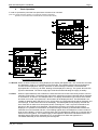
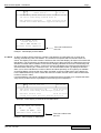
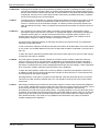
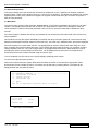
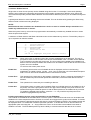
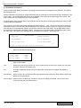
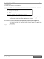
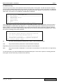
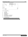
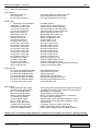
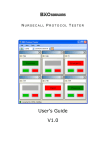
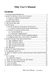
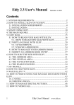
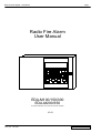
Radio Fire Alarm System – User Manual Page:1 Radio Fire Alarm User Manual EDA-M100/150/300 EDA-M200/350 For panels fitted with V3.00 or E3.00 and later firmware V3.01 V301_user Feb 2009 Electro-Detectors Radio Fire Alarm System – User Manual Page:2 Contents Page No V301_user 1. General Radio Systems 2 2. 2.1 2.2 2.3 2.4 2.5 2.6 2.7 2.8 Basic Operations Normal Fault Alarm Evacuate Alert Silence Reset Print 3 3 3 4 4 4 4 5 5 3. 3.1 3.2 3.3 3.4 3.5 Advanced Operation Main Menu Isolate / Enable Devices Test Modes & Options Change Options Event Log 6 6 7 8 8 9 4 Electrical connections and fuse ratings 13 5 Fault descriptions 16 6 Installation / system maintenance contact details 17 Feb 2009 Electro-Detectors Radio Fire Alarm System – User Manual Page:3 1.0 General Electro-Detectors has drawn from over eight years experience of manufacturing radio fire alarm systems and has taken into account the changing requirements of the market place to produce a system offering greater controllability of devices from the control panel. The MILLENNIUM system is a worthy successor to the wellestablished EDA series. At the heart of the MILLENNIUM system is a compact control panel designed around a 16bit processor and featuring surface mount technology. 16 times more powerful than its predecessor and capable of supporting 3 times the number of devices, the panel benefits from well designed and clearly labelled operational features. Versatile software means that the Millennium will interface readily with most other hardwired systems and is user friendly. Programming of devices can be carried out by either direct use of the internal keypad or via the PC interface. Excellent message quality is achieved as a result of a CCFL backlit 8 line liquid crystal display. As with all Electro-Detectors products, build quality is stringently controlled at every stage ensuring complete reliability of the system during operation. The fire alarm installed is a fully addressable radio system. Each device is individually identifiable by means of a unique unit number between 1 and 2999 inclusively. There is no wiring between units, control panels and sounders, the system communicating via short wave radio transmissions. No other radio equipment will interfere with the system and, likewise, the fire alarm will not interfere with any other radio equipment. For smaller installations a system has been designed to cater for 999 devices in twenty zones. The panel uses a smaller LED backlit 4 line liquid crystal display. This panel operates in a similar manner to other panels but has some advanced functionality omitted. The operation of the system is dependant on the configuration set by the commissioning engineer, but each installation is generally similar. When a smoke or heat detector detects an alarm condition or a break glass unit is operated, the relevant information will be displayed on the control panel. This includes the device location, unit number and zone of alarm. The sounders will operate. The situation should be investigated for the cause, and once under control the system can be silenced. Any subsequent alarm will operate the sounders once more and the relevant information for the new alarm being displayed on the screen. If the system detects any faults on any of the devices or the control panels e.g. mains fail or unit removal, a fault will be displayed. A buzzer will sound on the control panel to attract someone’s attention. This can be silenced until the cause of the problem is corrected. For further operation of the system refer to the remaining sections of this manual. If you have any queries on the operation of the panel, please contact the company that maintains the system, printed on the last page of this manual. If a particular option is not available, a suitable message will be displayed. Important No operator serviceable parts are contained in this panel. The Millennium range of control panels and detectors may only be installed, commissioned and serviced by an Electro-Detectors approved agent. Due to the specialised nature of our equipment we do not provide support to end users or non-approved agents. For advice or support contact the system maintenance company listed at the back of this manual. Always follow any safety advice or warnings given in this manual. Failure to do so may result in injury or damage to equipment. Always use appropriate common sense precautions when opening or operating the equipment. Due to our policy of continued product development the specification of the product or the information in this manual may be subject to change. V301_user Feb 2009 Electro-Detectors Radio Fire Alarm System – User Manual 2 Page:4 Basic Operation In order to operate the panel the front panel door will have to be unlocked. (Note: This section describes operation of a system with standard configuration. Operation is for the EDA-M100 and EDA-M150 unless otherwise stated) EDA-M100 and EDA-M150 EDA-M200 2.1 Normal When no faults or alarms are being displayed, the display will appear dark. The current time and date are displayed in area (3), not available on the EDA-200. The installing agents name and telephone number will be displayed in area (2). Whenever a radio message is received or transmitted the appropriate Rx or Tx box (1) will flash. Nothing will be displayed in area (4). The system Normal LED (6) will be illuminated. The mains supply light will be illuminated indicating the supply is healthy. 2.2 Fault V301_user When the panel detects a fault condition the internal buzzer will sound continuously and the common fault light will illuminate. The display back light will be switched on and the initial fault will be displayed on the first line, as shown in the example below. The display will detail the type of fault, which device and when it occurred. If programmed, a text location will be displayed below. The EDA-M200 is not capable of detailing dates and times for any of its events. Any subsequent faults will be displayed, and scroll through, on the bottom two lines of the display. The EDA-M200 will only display one fault at a time. Each fault is visible for a short period of time. Pressing the ↑ and ↓ keys will cause either the previous or the next fault to be displayed. This will then continue to scroll from the event being displayed. It is possible for 300 faults to be scrolled through. Window (3) will alternate between the total fault count and the date and time. The installing agents name and telephone number remains in area (2) of the display. In order to conserve power the LCD backlight will switch off 15 minutes after a fault occurs on any panel. If the mains supply is interrupted the fault will be indicated as above and the Mains Supply light will be extinguished. For a complete list of faults see appendix 5.0. The default fault relay is AUX 2 but may be reconfigured. Feb 2009 Electro-Detectors Radio Fire Alarm System – User Manual Rx Tx Page:5 A N Other Fire Systems 01455 534 217 12:33:29 21-11-99 1 Low Battery Smoke Detector 0143 12:33 21-11-99 1st Floor South Wing Outside Room 12 2 Unit Removal Callpoint 0142 12:34 21-11-99 Ground Floor Main Entrance Opposite Reception Example - Fault Display for EDA-M100 and EDA-M150 A N Other Fire 01455 534 217 1 UNIT REM SOUND 03 Ground floor opposit Text Line scrolls across the LCD Example - Fault Display for EDA-M200 2.3 Alarm An alarm condition will be caused by a smoke / heat detector, a break glass unit or some other sensing unit detecting a fire risk situation. The sounders will operate and the internal buzzer will sound. The display of the units in alarm is similar to that of the fault display. All alarms will override the fault display. The zone display (5) indicates the initial zone of alarm and the fire LEDs above the zone will flash. If another alarm condition occurs the zone display indicates the new zone momentarily and then reverts to initial zone of alarm. A new zone of fire is indicated by the internal buzzer pulsing for 2 seconds before returning to a continuous tone. The time and date location (3) displays a fault and alarm count, which indicates the number of alarms and faults presently on the system (not available on the EDA-M200). All zones that are in alarm are listed on the top middle portion of the display (2). For the EDA-M200 the top 2 lines contain the first zone of alarm, the last zone of alarm and the total number of zones in alarm. If a smoke detector only sends a single alarm message and does not follow up to complete the alarm verify then a pre alarm event is generated in the event log but not displayed. Rx Tx Zones in Alarm 056 001 004 051 12:33:29 21-11-99 1 Fire Zone 056 Callpoint 034 12:33 21-11-99 1st Floor South Wing Fire Escape by Room 12 2 Evacuate Control 0001 12:39 21-11-99 Ground Floor Main Entrance Behind Reception Example - Alarm Display for EDA-M100 and EDA-M150 1ST ZN LAST ZN TOTAL 04 04 01 1 ZONE 04 HEAT 003 Second floor outside Text Line scrolls across the LCD Example - Alarm Display for EDA-M200 V301_user Feb 2009 Electro-Detectors Radio Fire Alarm System – User Manual Page:6 2.4 Evacuate Pressing the evacuate button will operate the sounders if they are not already sounding. This will override an intermittent sounding alarm. ‘Evacuate’ will be displayed on the display along with the panel number where the button was pressed. The text location for this panel and the date and time is displayed. A buzzer on the control panel sounds continuously. By default AUX relay 1 operates and the hard-wired sounder circuits energise. 2.5 Alert The alert function is designed as a warning. Pressing this button will cause the sounders to sound an intermittent tone. It will not override an evacuate or alarm tone, but will be displayed on the screen in a similar way to the Evacuate message. The buzzer sounds continuously whilst in this state. By default AUX relay 1 does not operate and the hard-wired sounder circuits pulse once per second. 2.6 Silence If the system is in an alarm or alert state, from either a smoke detector, break glass or panel, pressing this button will silence the sounders. A message will appear on the screen indicating the operation is taking place. It can take several seconds for the complete system to silence. The internal buzzer will now sound intermittently. A subsequent alarm condition from a different unit or pressing either Evacuate or Alert will cause the sounders to re-sound. If a fault is being displayed operation of this button will silence the internal buzzer. Any subsequent faults will re sound the buzzer. In both of the above situations the silence LED above the button will be illuminated. The events remain on the screen. On the EDA-M200 the LED’s are not fitted and the status is indicated on the top line of the LCD. In alarm the silence operation by default clears the sounder relays and AUX 4; the AUX mask may be reconfigured using the PC software. 2.7 Reset Once the system has been silenced, whether it be a fault or alarm condition, Reset will cause the system to return to normal. The reset button is disabled for six seconds after the silence has been pressed. The display will be cleared and a message will appear indicating the system is resetting. If the alarms or faults persist they will be redisplayed and actioned upon accordingly. If there were faults prior to an alarm condition reset will cause the faults to be re-displayed. In alarm the reset operation clears AUX 1 and 3 by default. In fault the reset operation clears AUX 2 by default, but will clear the relays programmed to operate on fault using the PC. These options may be reconfigured by the system engineer. Pressing Reset for 3 seconds in a system normal state will cause the lamps test function to operate. This will in turn flash all LED’s and flash the LCD. This should be done as part of the routine weekly system test. 2.8 Print V301_user Momentarily pressing the print button will print earlier events in reverse order as previously displayed on the screen, starting with the most recent event first. When the required events have printed, a short press of the print button will cause the printing to cease. The print operation will terminate automatically once the entire log has been printed. A message appears on the LCD whilst the printer is finishing. This will take a few seconds as printing is terminated and the paper is fed out. To feed the paper through the printer press and hold the print button for the required amount of paper feed and then release the button. The printer is only available on the EDA-M150. If a printer is not fitted a suitable message will be displayed. Feb 2009 Electro-Detectors Radio Fire Alarm System – User Manual Page:7 3.0 Advanced Operation This section details use of the menus and the functions available to a user. A password is required to perform these functions. There are two levels of access, i/ a user and ii/ an engineer. The default user password for a newly supplied panel is 2222. If the password is forgotten an engineer will be required to gain access to the system to alter the user password. 3.1 Main Menu To enter the menu system, press the button labelled MENU. This function is disabled if the system is in an alarm condition. The display will prompt the user to enter a four digit password. There are five attempts to enter the correct password. If after five times the password is still not correct, the menu button will be disabled for thirty minutes. If the menu system is entered and no keys are pressed for five minutes the panel will exit the menu and return to normal operation. Once entered correctly the system will display momentarily that entry has been granted to a user and how many failed access attempts have been made since the last entry. The main menu, detailed below, will now be displayed. All menus operate in the same basic manner. The highlighted bar can be moved up and down using the ∧ and ∨ keys. Pressing enter will then select this option. The scroll bar will wrap round the screen. For example, to select Change Options press the ∨ key until Change Options is highlighted and press Enter. Alternatively the number preceding the option can be pressed for fast access. On the M200 panel the menu bar is not featured and therefore the menu item must be selected using the numeric keys. To exit completely from the menus to the system display repeatedly press cancel. To return to the previous menu press 0. Alarms will override the menu system. New faults will cause the buzzer to sound and the appropriate LED’s illuminate but will not override the menu. The buzzer can be silenced by pressing silence. The faults will be displayed when the user exits the menu. 1. 2. 3. 4. MAIN MENU Isolate / Enable Test Modes & Options Change Options View Event Log 0. Exit Use ↑↓ to highlight and press enter to select Main Menu for EDA-M100 and EDA-M150 1.Isol Dev 2.Isol Zone 3.Isol Aux 4.Event Log 5.Test Cancel -Exit Main Menu for EDA-M200 V301_user Feb 2009 Electro-Detectors Radio Fire Alarm System – User Manual Page:8 3.2 Isolate / Enable Devices Single units or areas of units (zones) can be disabled using this function. For example, if some work (building, welding, spray painting etc) was being performed that could possibly operate some detection units, then these units could be temporarily isolated. Both individual units and areas of detectors (zones) can be isolated through this menu. A pulsed panel buzzer is active indicating devices are isolated. This can be silenced by pressing the Silence key while no faults or alarms are being displayed. NOTE! Both Fault and alarm conditions are disabled when a device or zone is isolated. Always remember to reenable any isolated zones or devices. When the system is set-up, a time limit is programmed to automatically re-enable any isolated devices or zones when the period has expired. A maximum of fifteen devices and fifteen individual zones can be isolated at any one time. The auxiliary relays on up to 15 panels can also be isolated. ISOATE / ENABLE 1. Isolate Detector 2. Enable Detector 3. Isolate Zone 4. Enable Zone 5. Isolation of Aux 0. Exit Use ↑↓ to highlight and press enter to select Isolate Dev When this function is selected a list of the currently isolated devices is displayed. The user is prompted to enter the unit number of the device to be disabled. Units 1 to 2999 can be disabled. Type in the device number and press enter. The unit number will be added to the isolated list of devices. All units except sounders and actuators can be isolated. Devices that do not exist on the system can not be isolated. To exit from this screen press cancel. Enable Dev On selecting this function a list of isolated devices is displayed, the first in the list being highlighted. To enable a device, use the ∧ and ∨ keys to select the unit to be enabled and press enter. This unit will now be enabled and will be removed from the list. Isolate Zone This operates in the same way to the isolation of a detector. Zones 1 to 999 can be isolated. If a zone is isolated call points will still operate but transmitters, smoke and heat detectors will be isolated. Enable Zone This operates in the same way as re-enabling a detector. Isolate Aux The auxiliary relays on panels can be isolated. Either an individual panel can be isolated or all of the panels. The user is prompted to enter a two digit number relating to the panel number to be isolated. Entering 00 isolates all panels. A total of fifteen panels can be isolated at any one time. To enable the isolated panel auxiliary, press the ∧ or ∨ keys until the required panel to be enabled is highlighted and press enter. Isolating and enabling devices, zones and auxiliaries on the EDA-M200 This is similar to the EDA-M100 and EDA-M150. Once the option is selected units and zones can be isolated and enabled on the same respective screen. Devices do not have to be logged to the system to be isolated. To isolate a device or zone select the appropriate option and enter the number followed by ENTER. The isolated number will be displayed below. To isolate other numbers repeat the operation. To enable the zones or devices select the appropriate option and using the ∧ or ∨ keys position the cursor on the number to be enabled. Press enter to enable the number. The EDA-M200 panel only has the ability to communicate with 999 devices in 20 zones. V301_user Feb 2009 Electro-Detectors Radio Fire Alarm System – User Manual Page:9 3.3 Test Modes And Options The test mode facility allows the system to be tested with the minimum of disruption to the premises. The options are displayed below. All test modes will automatically re-enable themselves after a preset period. The timeout setting is displayed on the menu screen. On the EDA-M200 the timeout is not labelled but is located in the bottom right of the screen. This time-out value can only be altered by the system engineer. A pulsed panel buzzer is active while in test mode but can be silenced by pressing the Silence key while no faults or alarms are being displayed. To activate any of the test modes either highlight the option using the ∧ and ∨ keys and press enter or press the appropriate number. The new status will be displayed to the right hand side of the line. To enable the test modes ‘Exit and save’ must be selected. Pressing cancel will not alter the test mode status. On the EDA-M200 options are selected by pressing the appropriate number. The test menu on the EDA-M200 is available as option 5 from the main menu. The test menu is relocated when accessed as an engineer - see section 7.0. Test System Test:OFF Timeout:030min Aux:ENABLED Bells:ISOLATED Auto Silence:OFF Sound Area:ALARM Use ↑↓ to highlight,Ent-select,Cancel-Exit ↵ Menu for EDA-M100 and EDA-M150 1.Test 2.Aux 3.A.Sl 4.Zone OFF ENAB OFF ALARM 5.Bells ENAB 0.Done 030min Menu for EDA-M200 Test Whenever a test is being carried out, for the system to see the event as a routine test, this option should be selected. The default is off. Aux This option allows the auxiliary relays on all panels to be isolated or enabled. The default is enabled. Auto Silence With this option all sounders will silence automatically after 6 seconds. There will be a slight delay before all sounders silence. Zone of Alarm With this option enabled only sounders in the area of testing will operate. This can be used in conjunction with the auto silence option. V301_user Feb 2009 Electro-Detectors Radio Fire Alarm System – User Manual Page:10 3.4 Change Options This function is not available on the EDA-M200 panel. Selection of this displays a sub-menu allowing the user to change the date, time and user password. The menu is shown below. 1. 2. 3. 0. Change Options Change Date and Time Change User Password Change Language Exit Use ↑↓ to highlight and press enter to select Date and Time To change the date and time select option 1. Use the ∧ and ∨ keys to highlight the figure to be changed. Press enter to select the figure and it will start to flash. Use the ∧ or ∨ keys to change the value and press enter when finished. Once the date and time are correct highlight ‘Accept’ and press enter. Pressing cancel will exit without making any changes. Users Password To change the users password select option 2. The user will be prompted to enter the new password and then to re-enter the new password again. If the two passwords agree the password will be changed otherwise the old password will be reverted to. Passwords are at no point visible on the system. If the password is forgotten an engineer will have to be called to set a new password. Language V301_user Not implemented Feb 2009 Electro-Detectors Radio Fire Alarm System – User Manual Page:11 3.5 View Event Log The event log is the history of all operations that have taken place on the system. The last 999 events are stored. The information displayed includes an event number, the event type, the device number, the location, the date and the time the event occurred. By selecting this menu the following sub-menu appears. This allows you to selectively view events. If an option is not available a message will be displayed. VIEW EVENT LOG 1. All Events 2. Test Events 3. Engineering Events 4. Real Events 5. Fault Events 0. Exit Use ↑↓ to highlight and press enter to select Viewing the events, using any of the above options is essentially the same. Once selected the most recent event will be displayed as shown below. By using the ∧ or ∨ keys, the event log can be scrolled through to examine all events. If there is no event displayed with the event number then the end of the log has been reached. Pressing cancel will return to the menu. When viewing events other than ‘all events’ some events may appear blank. These are events not relating to the search selected. View All Events 3 Low Battery Smoke Detector 0143 12:33 21-11-99 1st Floor South Wing Outside Room 12 2 Unit Removal Callpoint 0142 12:34 21-11-99 Ground Floor Main Entrance Opposite Reception ↑↓ - scroll, Cancel - Exit All All events will be displayed including silence alarms, silence faults and resets. Test Only events that were performed in a test mode will be displayed. Engineering Only events that were performed by an engineer will be displayed. Real Only real events will be displayed i.e. events that occurred whilst not in a test mode or an engineering mode. To view the event log on the EDA-M200 select the appropriate option. There are no options for viewing particular event types. Use the cancel key to exit from the event log. V301_user Feb 2009 Electro-Detectors Radio Fire Alarm System – User Manual Page:12 4.0 Panel Power Supply Board Connections and fuse ratings Note! No operator serviceable parts are contained within this panel. Always refer to a qualified technician for parts and servicing Mains Power Supply Connection Details The Millennium range of panels require a separate fused spur rated at 230V a.c 50Hz capable of providing 300mA. This supply should not incorporate a switch and should be labelled “Fire Alarm Equipment – Do Not Switch Off”, The power supply terminal block incorporates an integrated fuse rated at 230V, 500mA. Note! Live electrical equipment. Any electrical installation should only be done by suitably qualified personnel. All wiring should be done in accordance with current regulations and be of sufficient standard as not to harm any persons or cause damage to the panel. Do not attempt to modify or alter any connections without consulting a qualified fire alarm engineer. Always ensure that the supply is completely isolated and locked out before working on any mains rated components. Always replace fuses with the same type and rating. Connection of mains supply (M100/M200/M300/M350). It is important that these instructions are followed correctly to avoid risk of injury or damage to the panel. The mains supply is connected into the terminal block located in the upper right hand corner of the panel. Always ensure that the wire insulation is trimmed to the correct length. It should be sufficiently long to allow the conductor to be securely gripped in the terminal block but should not leave any exposed wire visible once the conductor is inserted fully into the terminal block. Viewing the terminal block from the front insert the mains input to the top of the terminal block. The left hand terminal is the Live, the middle terminal is the Ground / Earth and the right hand terminal is the Neutral connection. Millennium Series Power Terminal Block V301_user Feb 2009 Electro-Detectors Radio Fire Alarm System – User Manual Page:13 4.1 Main Panel Power Supply Board Connections (EDA-M100/M150/M200) Connectors and Terminals CON1 CON2 CON3 To Receiver Unit To Processor Board To Expansion Board T1 T2 T3 T4 T5 T6 External Supply Ground External Supply 24V In Battery Ground Battery 12V In Printer Ground Printer 5V T7 T8 T9 T10 T11 T12 External Call Point Input Gnd External Call Point Input 5 V Ground External Monitor In External 24 V Output External Ground T13 T14 T15 T16 T17 T18 T19 T20 T21 T22 Auxiliary Relay 1 Common Auxiliary Relay 1 Norm Closed Auxiliary Relay 1 Norm Open Fault Relay 2 Common Fault Relay 2 Norm Closed Fault Relay 2 Norm Open Sounder Relay 1 Alarm + Sounder Relay 1 Alarm Sounder Relay 2 Alarm + Sounder Relay 2 Alarm - T23 T24 AC In 18V RMS AC In 18V RMS LK1 LK2 Antenna Monitoring Antenna Monitoring Fuses F1 F2 F3 F4 F5 F6 F7 F8 0.5A 3.15A 6.3A 3.15A 0.5A 6.3A 0.5A 0.5A V301_user Sounders and External 24V Supply Main 5V Power Supply to Processor Battery Printer (Control Panel Only) Battery Charger 24 External Supply Input (Control Panel Only) Sounder Circuit 2 Sounder Circuit 1 Feb 2009 Electro-Detectors Radio Fire Alarm System – User Manual Page:14 4.2 Repeater Panel Power Supply (EDA-M300/350) CON1 CON2 Connector to Receiver Connector to Main Processor T1 T2 T3 T4 T5 T6 T7 T8 T9 T10 T11 T12 AC In 18V RMS AC In 18V RMS Battery In Ground * Battery In 12V * External Callpoint +5V External Callpoint Ground External 24V Output External Monitor In Relay 1 Sounder (Alarm +) or Relay 1 Sounder (Alarm -) or Relay 2 Sounder (Alarm +) or Relay 2 Sounder (Alarm -) or LK1 LK2 Auxiliary NC or NO Auxiliary Common Fault NC or NO Fault Common Antenna Monitoring (See 5.2)** Antenna Monitoring (See 5.2)** * On very early repeater panels the battery connections were reversed to that given above ** On some versions of board the antenna monitoring links are vertical rather than horizontal. V301_user Feb 2009 Electro-Detectors Radio Fire Alarm System – User Manual 5.0 Page:15 Alarm and Fault Details Panel Alarms Evacuate Control XX Alert Control XX Fire Zn XXX Control XX Evacuate pressed on panel number XX Alert pressed on panel number XX Fire event generated from CP input Panel Faults C (Displayed in Zone Number) Interference 1 Control XX Interference 2 Control XX Tx / Rx Fail 1 Control XX Tx / Rx Fail 2 Control XX Mains Low Control XX Mains High Control XX Batt Low Control XX Batt High Control XX OC Flt Ant Control XX SC Flt Ant Control XX OC Flt Snd 1 Control XX SC Flt Snd 1 Control XX OC Flt Snd 2 Control XX SC Flt Snd 2 Control XX OC Flt Snd 3 Control XX SC Flt Snd 3 Control XX OC Flt Snd 4 Control XX SC Flt Snd 4 Control XX Wire Fault Control XX OC Flt CP Control XX SC Flt CP Control XX Comms Fl XX Control YY Disp. Fail Control XX Processor Failure Interference on Panel Frequency Interference on Device Frequency Transceiver fail on Panel Frequency Transceiver fail on Device Frequency Mains supply below 195 V AC Mains supply above 255 V AC Battery voltage below 8.5 V Battery voltage above 15V Antenna Open circuit Antenna Short circuit Sounder 1 Open Circuit Sounder 1 Short Circuit Sounder 2 Open Circuit Sounder 2 Short Circuit Sounder 3 Open Circuit Sounder 3 Short Circuit Sounder 4 Open Circuit Sounder 4 Short Circuit Monitor Input Open Circuit External Callpoint Open Circuit External Callpoint Short Circuit Panel YY has failed to communicate with panel XX Failure of main panel display Device Alarms Fire Zone XXX Smoke Det XXXX Fire Zone XXX Heat Det XXXX Fire Zone XXX Callpoint XXXX Fire Zone XXX Sounder XXXX Fire Zone XXX Wire Cct XXXX Fire Zone XXX External XXXX Fire Zone XXX Trans. XXXX Smoke detector fire event Heat detector fire event Callpoint fire event Sounder CP input fire event EDA400 wired interface fire event External wired interface fire event Transmitter fire event Device Faults Verify Fail Smoke Det XXXX Unit Removal Callpoint XXXX Batt 1 Low Sounder XXXX Batt 2 Low Sounder XXXX Batt Low Smoke Det XXXX Int. Fail Sounder XXXX OC Flt Callpoint XXXX SC Flt Trans. XXXX Extnal. Flt Sounder XXXX TX/RX Fail Sounder XXXX Wire Fault Smoke Det XXXX Type Error Callpoint XXXX Verify Fail (Smoke,Heat,Callpoint,Sounder,Transmitter) Unit Removal (Smoke, Heat, Callpoint,Sounder,Trans) Main Battery Low (Sounder) Standby Battery Low (Sounder) Battery Low (Smoke,Heat,Callpoint, Transmitter) Processor Failure (Sounder) External Open Circuit Wire Fault (Callpoint, Trans) External Short Circuit Wire Fault (Callpoint, Trans) External Fault Transmitter / Receiver Failure (Sounder) External Wire Fault (Smoke, heat, Sounder) Device type is different to that specified in options Always report any fault messages displayed on the panel to the system maintenance company promptly. V301_user Feb 2009 Electro-Detectors Radio Fire Alarm System – User Manual Page:16 6.0 Installation and maintenance information This system was installed by Date Telephone Number After hours telephone number Installer’s name This system is maintained by Telephone number After hours / Emergency telephone number Contract Number V301_user Feb 2009 Electro-Detectors