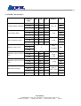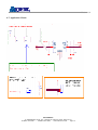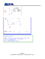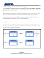
1
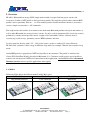
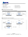
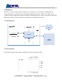
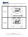
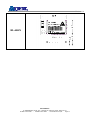
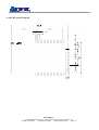
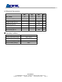
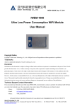
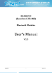
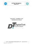
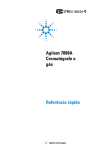
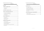
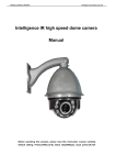
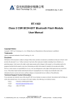
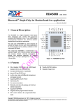
Version 1.2
Product Specification
Bluetooth v4.0 BLE Single Mode Module
[Generic & AT-command Version]
BL-4011
Version: 1.2
Atech OEM Inc.
7F, AAEON Building, N0.43, Sec. 4, Keelung Rd., Taipei City 10607, Taiwan, R.O.C.
Tel: 886-2-2377-0282
Fax:886-2-2377-0283
www.atechoem.com/wl
Page.
1
Version 1.2
Revision History
Edition #
Reason for revision
Issue Date
1.0
Initial Document
2014/3/6
1.1
Modify Application Circuit
2014/5/6
1.2
Modify Software & Operation Mode
2015/1/30
Atech OEM Inc.
7F, AAEON Building, N0.43, Sec. 4, Keelung Rd., Taipei City 10607, Taiwan, R.O.C.
Tel: 886-2-2377-0282
Fax:886-2-2377-0283
www.atechoem.com/wl
Page.
2
Version 1.2
Copyright Notice
Copyright © 2010 AtechOEM Technology Co., Ltd.
All Rights Reserved.
Reproduction without permission is prohibited.
Trademarks
AtechOEM is a registered trademark of AtechOEM Technology Co., Ltd.
Disclaimer
Information in this document is subject to change without notice and does not represent a commitment on the part of
AtechOEM. AtechOEM provides this document “as is,” without warranty of any kind, either expressed or implied, including,
but not limited to, its particular purpose. AtechOEM reserves the right to make improvements and/or changes to this manual,
or to the products and/or the programs described in this manual, at any time. Information provided in this manual is intended to
be accurate and reliable. However, AtechOEM assumes no responsibility for its use, or for any infringements on the rights of
third parties that may result from its use. This product might include unintentional technical or typographical errors. Changes
are periodically made to the information herein to correct such errors, and these changes are incorporated into new editions of
the publication.
Technical Support Contact Information
If you encounter any technical issues while using BL-4011, do not hesitate to contact us @AtechOEM. Our technical staff will
help you resolve the technical issues. You can contact us by email or phone. The following is our technical contact:
•Hours:
9:30AM to 5:30PM (GMT+08:00)
•Phone:
+886.2.2377.0282
Atech OEM Inc.
7F, AAEON Building, N0.43, Sec. 4, Keelung Rd., Taipei City 10607, Taiwan, R.O.C.
Tel: 886-2-2377-0282
Fax:886-2-2377-0283
www.atechoem.com/wl
Page.
3
Version 1.2
CONTENTS
1. OVERVIEW ........................................................................................................................................5
1.1. MODEL ................................................................................................................................................5
2. TYPICAL APPLICATIONS ..........................................................................................................6
3. PRODUCT INFORMATION ........................................................................................................7
4. HARDWARE .......................................................................................................................................8
4.1. BLOCK DIAGRAM.................................................................................................................................8
4.2 PIN ASSIGNMENT ..................................................................................................................................8
4.3. MECHANICAL SPECIFICATION ............................................................................................................10
4.4. PCB LAYOUT FOOTPRINT ..................................................................................................................12
4.5. ELECTRICAL CHARACTERISTICS ........................................................................................................13
4.6. RADIO CHARACTERISTICS..................................................................................................................14
4.7. APPLICATION CIRCUIT........................................................................................................................15
5. SOFTWARE & OPERATION MODE: DATA-TRANSFER APPLICATION .........17
5.1. APPLICATION ARCHITECTURE WITH CLIENT-MODE AND SERVER-MODE .............................................17
5.2. SPP CONNECTION EXAMPLE IN AT-COMMAND MODE ........................................................................18
5.3. CONFIGURATION IN SERVER MODE ....................................................................................................19
5.4. AT COMMAND SPECIFICATION ...........................................................................................................21
Atech OEM Inc.
7F, AAEON Building, N0.43, Sec. 4, Keelung Rd., Taipei City 10607, Taiwan, R.O.C.
Tel: 886-2-2377-0282
Fax:886-2-2377-0283
www.atechoem.com/wl
Page.
4
Version 1.2
1. Overview
BL-4011, Bluetooth low energy (BLE) single mode module is targeted for low power sensors and
accessories. It offers GATT profile as the based lower profile. We could also provide other standard BLE
profiles such as proximity, find me … etc. The module provides flexible hardware interfaces to connect
sensors, simple user interfaces – AT commands.
The single mode radio enables it to connect to the dual mode Bluetooth products already in the market, as
well as other Bluetooth low energy devices/ sensors. It can be used in equipments like a heart rate sensors,
pedometers, watches, blood pressure meters, weight scales, households sensors, collector devices,
security tags, wireless keys, proximity sensors, HID keyboards and mice.
It can be powered directly with 1.8V ~ 3.6V power source, such as a standard 3V coin cell battery.
BL-4011 only consumes a little energy in different sleep mode, for example 780nA in lowest power sleep
mode.
AtechOEM provides a proprietary GATT-based profile to our customers. The profile is similar to the
classic SPP (Serial Port Profile) described in Bluetooth v2.1. Customers could use this special profile to
transfer raw data between GATT-based connection in their application. AtechOEM also offer customized
firmware services to meet specific applications more tightly.
1.1. Model
Following Table shows the different models in BL-4011 series.
BL-4011A
BL-4011E
BL-4011N
Chip antenna on board
U.FL connector
RF Pin Out
Atech OEM Inc.
7F, AAEON Building, N0.43, Sec. 4, Keelung Rd., Taipei City 10607, Taiwan, R.O.C.
Tel: 886-2-2377-0282
Fax:886-2-2377-0283
www.atechoem.com/wl
Page.
5
Version 1.2
2. Typical Applications
Home automation
Sports & fitness
Industrial automation
Security & Proximity
Health care & Consumer wellness
Sensors & Controls
Mobile phone accessories
Small data transferring
■ Single Mode Connection Logical Diagram
Following diagram describes how to use BL-4011 in an application.
■ Single/Dual Mode Connection Logical Diagram
Following diagram describes how to use BL-4011 and other Bluetooth modules in an application.
Atech OEM Inc.
7F, AAEON Building, N0.43, Sec. 4, Keelung Rd., Taipei City 10607, Taiwan, R.O.C.
Tel: 886-2-2377-0282
Fax:886-2-2377-0283
www.atechoem.com/wl
Page.
6
Version 1.2
3. Product Information
■ Product Number : BL-4011
■ Product Description: Bluetooth v4.0 Single Mode BLE 1010 Module
■ Product Features:
Chip
CSR1010
Standard
Bluetooth v4.0 Single mode / BLE
EEPROM
256kbits
RF band
2.4~2.4835GHz ISM band
Host Interface
UART
Debug Interface
SPI
Digital Interface
UART / GPIO / I2C
Analog Interface
AIO
RF Output Power
Up to 8.5dBm Typically
Sensitivity
>-93dBm
Antenna
Chip Antenna / U.FL connector / RF Pin Out
Power voltage
1.8 V ~ 3.6V
Dimension
20.7mm x 12.6mm x 1.7mm
Atech OEM Inc.
7F, AAEON Building, N0.43, Sec. 4, Keelung Rd., Taipei City 10607, Taiwan, R.O.C.
Tel: 886-2-2377-0282
Fax:886-2-2377-0283
www.atechoem.com/wl
Page.
7
Version 1.2
4. Hardware
BL-4011 is a surface-mount module designed to be integrated to a system board as a Bluetooth low
energy subsystem or standalone system. The power supply ranges from 1.8VDC to 3.6 VDC, so it is
suitable for battery application. Digital data (PIO) and analogue interface (AIO) are supported in BL-4011.
Following sections describe all hardware specifications and application reference.
4.1. Block Diagram
4.2 Pin Assignment
The following picture shows pinouts of BL-4011 from the top of the module.
Atech OEM Inc.
7F, AAEON Building, N0.43, Sec. 4, Keelung Rd., Taipei City 10607, Taiwan, R.O.C.
Tel: 886-2-2377-0282
Fax:886-2-2377-0283
www.atechoem.com/wl
Page.
8
Version 1.2
Pin Definition:
Pin
Name
1
GND
2
RF
3
GND
4
WAKE
Type
Note
Passive
Ground
In/Out
RF Port
Passive
Ground
In
Wake up BL-4011
If in Hibernate or Dormant mode.
5
AIO2
In/Out
Analog I/O
6
AIO1
In/Out
Analog I/O
7
AIO0
In/Out
Analog I/O
8
PIO0 / UART Tx
In/Out
General Purpose I/O
9
PIO1 / UART Rx
In/Out
General Purpose I/O
10
PIO3
In/Out
General Purpose I/O
11
PIO4
In/Out
General Purpose I/O
12
SPI CLK
In/Out
Internal Testing Use
13
SPI CSB
In
Internal Testing Use
14
SPI MOSI
Out
Internal Testing Use
15
SPI MISO
In
Internal Testing Use
16
PIO9
In/Out
General Purpose I/O
17
PIO10
In/Out
General Purpose I/O
18
PIO11
In/Out
General Purpose I/O
19
SPI / PIO # SEL
20
PIO2
In/Out
General Purpose I/O
21
I2C SCL
In/Out
I2C Clock In/Out
22
I2C SDA
In/Out
I2C Data In/Out
23
VDD
Power
Main Power Supply
24
GND
Passive
In
Function Selection
Ground
Atech OEM Inc.
7F, AAEON Building, N0.43, Sec. 4, Keelung Rd., Taipei City 10607, Taiwan, R.O.C.
Tel: 886-2-2377-0282
Fax:886-2-2377-0283
www.atechoem.com/wl
Page.
9
Version 1.2
4.3. Mechanical Specification
BL-4011A
BL-4011E
Atech OEM Inc.
7F, AAEON Building, N0.43, Sec. 4, Keelung Rd., Taipei City 10607, Taiwan, R.O.C.
Tel: 886-2-2377-0282
Fax:886-2-2377-0283
www.atechoem.com/wl
Page.
10
Version 1.2
BL-4011N
Atech OEM Inc.
7F, AAEON Building, N0.43, Sec. 4, Keelung Rd., Taipei City 10607, Taiwan, R.O.C.
Tel: 886-2-2377-0282
Fax:886-2-2377-0283
www.atechoem.com/wl
Page.
11
Version 1.2
4.4. PCB Layout Footprint
Atech OEM Inc.
7F, AAEON Building, N0.43, Sec. 4, Keelung Rd., Taipei City 10607, Taiwan, R.O.C.
Tel: 886-2-2377-0282
Fax:886-2-2377-0283
www.atechoem.com/wl
Page.
12
Version 1.2
4.5. Electrical Characteristics
Min
Typ.
Max.
Unit
1.8
3.3
3.6
V
Normal Standby @ 3.3V
-
1.39
-
mA
TX (Normal mode) @ 3.3V
-
-
22.77
mA
RX (Normal mode) @ 3.3V
-
-
20.88
mA
Shallow Sleep @ 3.3V
-
-
486
uA
Deep Sleep @ 3.3V
-
-
4.9
uA
Hibernate Sleep @ 3.3V
-
-
1.9
uA
Dormant Sleep @ 3.3V
-
-
900
nA
Supply Voltage
■ Operating Conditions
Voltage Range
1.8V ~ 3.6V
o
o
o
o
Operating Temperature Range
-30 C ~ 85 C
Storage Temperature Range
-40 C ~ 85 C
Relative Humidity (Operating)
≤90%
Relative Humidity (Storage)
≤90%
Atech OEM Inc.
7F, AAEON Building, N0.43, Sec. 4, Keelung Rd., Taipei City 10607, Taiwan, R.O.C.
Tel: 886-2-2377-0282
Fax:886-2-2377-0283
www.atechoem.com/wl
Page.
13
Version 1.2
4.6. Radio Characteristics
Frequency
Min
Typ
Max
BT Spec.
Unit
2.402
-
8.56
-
2.440
-
8.99
-
2.480
-
8.99
-
dBm
2.402
-
-92
-
dBm
2.440
-
-92
-
2.480
-
-92
-
dBm
2.402
-
-
kHz
2.440
-
2.480
-
(GHz)
Tx Output Power (Average)
Rx Sensitivity (FER)
Carrier Frequency Offset
±10
±10
±10
-
<=-70
±150
dBm
dBm
kHz
kHz
FER
-5
2.440
-20 ~ 10
-
2.402
Maximum Input Level
dBm
<= 30.800 %
dBm
2.480
Modulation Characteristics
(F1)
Modulation Characteristics
(F2)
PER Report Integrity
Antenna Gain
2.402
-
253.5
262.5
225 <
kHz
2.440
-
260.2
265.3
F1avg
kHz
2.480
-
255.9
262.6
< 275
kHz
2.402
-
225.8
214.3
2.440
-
228.2
211.4
2.480
-
222.7
211.1
Cycle 1
-
50
-
Cycle 2
-
50
-
Cycle 3
-
50
-
-
-
0.5
-
kHz
>= 185
kHz
kHz
50.0 <=
PER <= 65.4
%
%
%
-
dBi
Atech OEM Inc.
7F, AAEON Building, N0.43, Sec. 4, Keelung Rd., Taipei City 10607, Taiwan, R.O.C.
Tel: 886-2-2377-0282
Fax:886-2-2377-0283
www.atechoem.com/wl
Page.
14
Version 1.2
4.7. Application Circuit
Atech OEM Inc.
7F, AAEON Building, N0.43, Sec. 4, Keelung Rd., Taipei City 10607, Taiwan, R.O.C.
Tel: 886-2-2377-0282
Fax:886-2-2377-0283
www.atechoem.com/wl
Page.
15
Version 1.2
Atech OEM Inc.
7F, AAEON Building, N0.43, Sec. 4, Keelung Rd., Taipei City 10607, Taiwan, R.O.C.
Tel: 886-2-2377-0282
Fax:886-2-2377-0283
www.atechoem.com/wl
Page.
16
Version 1.2
5. Software & Operation Mode: Data-Transfer Application
The special firmware in BL-4011 supports two different operation modes: Client mode and Server mode.
This special firmware allows BL-4011 to transfer data through the UART interface, which is similar to the
SPP profile in Bluetooth v2.1 standard.
BL-4011 with Client-mode firmware can initiate the connecting process between client and server. With
Server-mode firmware, BL-4011 can advertise its information and wait for the client’s connecting.
AtechOEM also can provide standard GATT-based profiles issued in Bluetooth SIG. We also provide
customized firmware to our customers to apply to different applications.
5.1. Application Architecture with Client-mode and Server-mode
Application architecture of BL-4011 with Client and Server mode is showed as below. The Client-mode
also can be connected by an smart phone based on GATT connection. The data can be transferred through
an UART interface or an APP on a smart phone.
Atech OEM Inc.
7F, AAEON Building, N0.43, Sec. 4, Keelung Rd., Taipei City 10607, Taiwan, R.O.C.
Tel: 886-2-2377-0282
Fax:886-2-2377-0283
www.atechoem.com/wl
Page.
17
Version 1.2
5.2. SPP Connection Example in AT-command mode
The following example describes simple connecting process between client and server mode in BL-4011.
Atech OEM Inc.
7F, AAEON Building, N0.43, Sec. 4, Keelung Rd., Taipei City 10607, Taiwan, R.O.C.
Tel: 886-2-2377-0282
Fax:886-2-2377-0283
www.atechoem.com/wl
Page.
18
Version 1.2
5.3. Configuration in Server Mode
■ Default Configurations in Server Mode:
Bluetooth
UART
Profile
GATT / BLE_SPP (Private)
Baud Rate
2400 bps
Device Name
BLE_SPP
Data Bits
8
BLE_SPP Service UUID
0x3a1bc6e0fb0611e1b9c20002a5d5c51b
Parity
No
BLE_SPP_DATA
0xcc330a40fb0911e1a84d0002a5d5c51b
Stop Bits
1
characteristic UUID
BLE SPP RemoteIO
0xd2127900f28e11e2b7780800200c9a66
Characteristic UUID
■ Hardware configuration:
PIO
3
4
9
Name
PIO3
PIO4
PIO9
Description
States
State controlled by remote device. Output state is low state after boot.
Direction
Output
Output
Output
Low state less than 4 second: change state. (reference to state button
configuration table described at below)
10
State Button
Input
Low state more than 4 second: reset default
11
Link LED
Output
High: LED On
Low: LED Off
■ LED Status:
Status
Link LED steadily on
Link LED blinking
Descriptions
Connection established.
Server role: Device is advertising.
Client role: Device is scanning.
Link LED off
No power supply or device is idle.
■ State button configuration:
Client Role
Original State
New State
Idle
Connecting
Scanning
Idle
Description
Connect to the device specified by “DEVICE= “.
Abort scanning and return to idle state.
Atech OEM Inc.
7F, AAEON Building, N0.43, Sec. 4, Keelung Rd., Taipei City 10607, Taiwan, R.O.C.
Tel: 886-2-2377-0282
Fax:886-2-2377-0283
www.atechoem.com/wl
Page.
19
Version 1.2
Connecting
Connected
Server Role
Original
State
Idle
Advertising
Connected
Idle
Idle
Abort connecting and return to idle state.
Disconnect and return to idle state.
New State
Description
Advertising
Idle
Idle
Start advertising
Abort advertising and return to idle state.
Disconnect and return to idle state.
Notice
The adaptor operates at either command mode or data mode.
The adaptor only accepts commands at command mode, and only transmits data at data mode. The
adaptor could receive data whether its operational mode is command mode or data mode while the
adaptor has connected with another device.
The adaptor always operates at command mode after boot.
The operational mode will NOT be changed whether two devices has been connect or disconnect. User
should be changing it manually.
Atech OEM Inc.
7F, AAEON Building, N0.43, Sec. 4, Keelung Rd., Taipei City 10607, Taiwan, R.O.C.
Tel: 886-2-2377-0282
Fax:886-2-2377-0283
www.atechoem.com/wl
Page.
20
Version 1.2
5.4. AT Command Specification
Setup Command Set (capital letter or lowercase letter is allowed)
Command Value
Description
+++
Set the local adaptor change the data mode into command
mode. The time interval between character will be more than
the time: [1 sec] +++ [1 sec]
This command should NOT include the terminal characters
“\r” or “\n”.
All command listed at below should include the terminal character “\r\n”
EXIT
Put the local adaptor into data mode.
ADDRESS=
?
Inquire the Bluetooth Address of the local adaptor.
This command is used to start advertising. This command is
ADVERT=
available only when the adaptor is in the server role. Reponse “End
advertising process” if the advertising time out and without any
connection.
Y
N
Check the connection status between control terminal and the local
adapter. Response: “OK” when the connection is ok.
This command is used to enable/disable auto-advertising feature. It
is available only when the adaptor is in the server role.
AT
AUTOADV=
Y
N
The server role adapter will automatically enter advertising
state.
The server role adapter will NOT automatically enter
advertising state.
This command is used to specify the baud rate of COM port.
BAUD=
(Default)
2400
4800
9600
19200
38400
57600
115200
R
?
CONNECT=
1~8
?
P
N
DEFAULT=
Start advertising
Stop advertising
2400 bps
4800 bps
9600 bps
19200 bps
38400 bps
57600 bps
115200 bps
Restore the default settings. (Baud rate =2400 bps)
Inquire the current baud rate.
This command is used to establish a connection manually. It is
available only when the adaptor is in the client role.
Connect the adaptor to a Bluetooth device in the neighborhood found
through “SCAN=?”
Display the MAC address of the latest connected device.
Connect to the device specified by “DEVICE= “.
Disconnect the two adapters in the command mode.
This command is used to restore the default settings and originate a
warm start.
Atech OEM Inc.
7F, AAEON Building, N0.43, Sec. 4, Keelung Rd., Taipei City 10607, Taiwan, R.O.C.
Tel: 886-2-2377-0282
Fax:886-2-2377-0283
www.atechoem.com/wl
Page.
21
Version 1.2
Restore the default settings.
The command will re-start the system for 1 second.
Specify device is a top priority device when the client device trying
DEVICE=
to connect. This command is only avaiable when auto-connection.
Xxxxxxxxxxxx “xxxxxxxxxxxx” is a string of 12 hexadecimal digits.
Clear the specify device content.
R
Inquiry the designated address that can be paired and connected.
?
This command is used to enable/disable auto-pair feature.
AUTOPAIR=
Start the aotu-pair process.
Y
NAME=
This command is used to specify a name for the adaptor.
“xx….xx” is a character string with the length from 2 to 20.
xx…xx
Restore the default settings name=“BLE SPP”
R
Y
PARITY=
(Default)
?
Inquire the name of the local adaptor.
N
O
E
?
None parity bit
Odd parity bit
Even parity bit
Inquire the current setting.
This command is used to specify parity bit setting of COM port.
PIO[para]=
H
L
PROMPT=
(Default)
N
Y
?
ROLE=
(Default)
C
S
?
This command is used to set remote pio output state.
[para] is the number of PIO interested to control.
Set remote PIO output high state.
Set remote PIO output low state.
The command is used to decide whether result messages are
prompted when Setup commands are executed. The result messages
are: OK/ERROR for command execution, or
CONNECT/DISCONNECT/Try Connect Device for connection
status.
Not prompt result messages.
Prompt result messages.
Inquire the current setting.
This command is used to specify whether the adaptor is in the
master or slave role. If the device role is changed, the adaptor
will reboot.
Set the adaptor to the client role.
Set the adaptor to the server role.
Inquire the current role of the adaptor.
RESET=
Y
RSSI=
?
SCAN=
Reboot the adaptor.
Received signal strength indication
Display the Received signal strength indication in command
mode when connected.
This command is used to search for any Bluetooth device
which supported Atech-SPP service in the neighborhood within
10 sec. If any device is found, its name and its
12-digit-address will be listed. The search ends with a message
“Inquiry ends. xx device(s) found.” This command is available
Atech OEM Inc.
7F, AAEON Building, N0.43, Sec. 4, Keelung Rd., Taipei City 10607, Taiwan, R.O.C.
Tel: 886-2-2377-0282
Fax:886-2-2377-0283
www.atechoem.com/wl
Page.
22
Version 1.2
only when the adaptor is in the client role by manual.
?
STATUS=
?
STOP=
(Default)
1
2
?
VERSION=
?
Inquire Bluetooth devices in the neighborhood, listing 8 devices the
maximum.
Inquire all the current setting of the adapter.
Display all the current setting of the adapter
This command is used to specify one or two stop bits of COM
port.
One stop bit.
Two stop bits.
Inquire the current setting.
This command is used to inquiry the firmware version.
Inquire the version codes.
Atech OEM Inc.
7F, AAEON Building, N0.43, Sec. 4, Keelung Rd., Taipei City 10607, Taiwan, R.O.C.
Tel: 886-2-2377-0282
Fax:886-2-2377-0283
www.atechoem.com/wl
Page.
23
Version 1.2
Federal Communication Commission Interference Statement
This equipment has been tested and found to comply with the limits for a Class B digital device, pursuant
to Part 15 of the FCC Rules. These limits are designed to provide reasonable protection against harmful
interference in a residential installation.
This equipment generates, uses and can radiate radio frequency energy and, if not installed and used in
accordance with the instructions, may cause harmful interference to radio communications. However,
there is no guarantee that interference will not occur in a particular installation. If this equipment does
cause harmful interference to radio or television reception, which can be determined by turning the
equipment off and on, the user is encouraged to try to correct the interference by one of the following
measures:
. Reorient or relocate the receiving antenna.
. Increase the separation between the equipment and receiver.
. Connect the equipment into an outlet on a circuit different from that to which the receiver is connected.
. Consult the dealer or an experienced radio/TV technician for help.
FCC Caution: To assure continued compliance, any changes or modifications not expressly approved by
the party responsible for compliance could void the user's authority to operate this equipment. (Example use only shielded interface cables when connecting to computer or peripheral devices).
End Product Labeling
This transmitter module is authorized only for use in devices where the antenna may be installed such
that 20 cm may be maintained between the antenna and users. The final end product must be labeled in
visible area with the following: “Contains FCC ID: YX6BL4011”
End Product Manual Information
The user manual for end users must include the following information in a prominent location
“IMPORTANT NOTE: To comply with FCC RF exposure compliance requirements, the antenna used for
this transmitter must be installed to provide a separation distance of at least 20cm from all persons and
must not be colocated or operating in conjunction with any other antenna or transmitter.” This device
complies with part 15 of the FCC rules. Operation is subject to the following two conditions (1) This
device may not cause harmful interference and (2) This device must accept any interference received,
including interference that may cause undesired operation.
IMPORTANT NOTE:
In the event that these conditions can not be met (for example certain laptop
configurations or colocation with another transmitter), then the FCC authorization is no longer considered
valid and the FCC ID can not be used on the final product. In these circumstances, the OEM integrator will
be responsible for reevaluating the end product (including the transmitter) and obtaining a separate FCC
authorization. This device is intended only for OEM integrators under the following conditions: The
antenna must be installed such that 20 cm is maintained between the antenna and users. As long as a
condition above is met, further transmitter test will not be required. However, the OEM integrator is still
responsible for testing their end product for any additional compliance requirements required with this
module installed (for example, digital device emissions, PC peripheral requirements, etc.).
Atech OEM Inc.
7F, AAEON Building, N0.43, Sec. 4, Keelung Rd., Taipei City 10607, Taiwan, R.O.C.
Tel: 886-2-2377-0282
Fax:886-2-2377-0283
www.atechoem.com/wl
Page.
24