1
4.2.12 Power Supply Branch
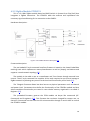
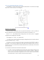
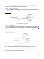
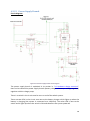
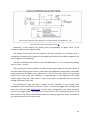
Circuit diagram:
Figure 4.2.12: Power Supply Branch Circuit Diagram
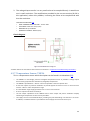
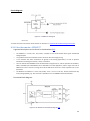
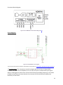
The power supply branch is explained in its section in “4.1 Hardware design overview”.
Here can be viewed the power supply branch (battery charger + battery + voltage regulator)
together with the charge pump.
There is a switch in the circuit used to turn on and of the whole system.
There are two LEDs in the circuit: one next to the battery charger which lights up when the
battery is charging (the system is connected to a USB host). The other LED is next to the
switch and it lights up when the switch is ON and therefore the system powered.
28