1
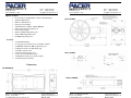
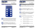
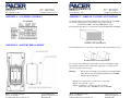
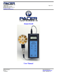
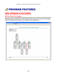
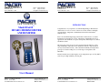
TM
TM
PO Box 726
60 Dunbar Street
Keene, NH 03431 USA
Phone: (603) 352-0187
Fax:
(603) 352-1036
[email protected]
PO Box 726
60 Dunbar Street
Keene, NH 03431 USA
Phone: (603) 352-0187
Fax:
(603) 352-1036
[email protected]
TM
INTRODUCTION
™
Model DA430
HYGRO-THERMOMETER
ANEMOMETER
Congratulations on your purchase of a DA430 Digital Hygro-Thermometer
Anemometer! You now own one of the most accurate, reliable, and highly
regarded airflow, temperature, and humidity measurement instruments
available today.
Pacer’s model DA430 digital hygro-thermometer anemometer is a versatile
instrument for measuring air velocity, temperature, and humidity in various
applications such as HVAC, aerospace development, industrial process airflow,
and fluids research.
The rugged yet precise air probe can be used in airstreams that have a wide
range of humidity, temperature and contaminants without compromising air
velocity measurement accuracy. The combination humidity and temperature
probe gives accurate readings across a wide range of temperatures and
humidities.
Features include custom cable lengths, service temperatures up to 212˚F (100˚C)
at the air probe, high reliability, and long life.
User Manual
DA430™ User Manual, PN 10140
Rev 1.8, 10-Jun-2008
Copyright © 2008, Pacer Instruments, Inc.
Pacer Instruments, Inc
www.pacer-instruments.com
Page 1 of 28
DA430™ User Manual, PN 10140
Rev 1.8, 10-Jun-2008
Copyright © 2008, Pacer Instruments, Inc.
Pacer Instruments, Inc
www.pacer-instruments.com
Page 2 of 28
TM
TM
PO Box 726
60 Dunbar Street
Keene, NH 03431 USA
Phone: (603) 352-0187
Fax:
(603) 352-1036
[email protected]
PO Box 726
60 Dunbar Street
Keene, NH 03431 USA
Phone: (603) 352-0187
Fax:
(603) 352-1036
[email protected]
SECTION 1 - SPECIFICATIONS
Ranges:
Air Probe AP275:
Air Probe AP100:
Warranty
This product is fully warranted against defective materials and/or
workmanship for a period of one year after purchase, provided it was not
improperly used. For your protection, please use this product as soon as
possible. If returned, it must be securely wrapped, sent prepaid and insured
to:
Pacer Instruments, Inc.
PO Box 726
60 Dunbar Street
Keene, New Hampshire 03431
USA
Please include a note with name, address, telephone number and description
of the problem. Although we provide assistance on Pacer products both
personally and through our literature, it is still the total responsibility of the
customer to determine the suitability of the product for use in their
application.
This manual is provided by Pacer Instruments without any kind of warranty.
Precautions have been taken in accurately preparing this manual; however,
we neither assume responsibility for any omissions or errors that may
appear nor assume liability for any damages that result from the use of the
products in accordance with the information contained in the manual.
DA430™ User Manual, PN 10140
Rev 1.8, 10-Jun-2008
Copyright © 2008, Pacer Instruments, Inc.
Pacer Instruments, Inc
www.pacer-instruments.com
Page 3 of 28
40 to 7800 ft/min (feet per minute)
0.2 to 40.00 m/sec (meters per second)
60 to 6800 ft/min
0.3 to 35.00 m/sec
Relative Humidity (%RH):
5.0 to 95.0 %RH
Temperature (using combination HTP202 probe): -4° to 176°F
(-20° to 80°C)
Temperature (using optional RTD probe):
-148° to 1112°F
(-100° to 600°C)
Accuracy:
Air Velocity:
±1.0% of reading ±1 digit
Relative Humidity:
±2.0 %RH
Temperature:
±(0.3°C + 0.2% of reading in °C)
Temperature accuracy examples: ±0.3°C at 20°C
±0.5°F at 68°F
Resolution:
Air Velocity:
1 ft/min or 0.01 m/sec
Relative Humidity:
0.1 %RH
Temperature:
0.1˚F or 0.1˚C (1˚F below -99.0˚F)
Operating Temperature:
Instrument:
Air Probes:
HTP202 Probe:
32˚ to 125˚F (0˚ to 50˚C)
-22˚ to 212˚F (-30˚ to 100˚C)
-4˚ to 176˚F (-20˚ to 80˚C)
Power Supply:
3 AA alkaline batteries
Battery Life:
Approx. 150 hours, without backlight
Battery check:
Automatic low battery display
Display:
0.5” LCD, 4 digits, with LED backlight
DA430™ User Manual, PN 10140
Rev 1.8, 10-Jun-2008
Copyright © 2008, Pacer Instruments, Inc.
Pacer Instruments, Inc
www.pacer-instruments.com
Page 4 of 28
TM
TM
PO Box 726
60 Dunbar Street
Keene, NH 03431 USA
Phone: (603) 352-0187
Fax:
(603) 352-1036
[email protected]
Options Available:
• Protective Boot and Splash-Proof Seal for the Instrument
• USB Communications
• RS232 Communications
• Analog 0-5 Volt Output
• Additional Probes: AP275, AP100, HTP202
• Extra extension and/or flexible rods
• Custom cable lengths
• Immersion RTD temperature probe
• Surface RTD temperature probe
• Air RTD temperature probe
Included:
•
•
•
•
•
•
•
•
•
(1) DA430 Instrument
(1) Vane-type probe head, choice of AP100 or AP275
(1) HTP202 combination RH / temperature probe
(3) Rigid extension rods with handle grip
(1) Flexible extension rod
(1) Probe connection cable, 5 ft.
(3) Size AA 1.5V alkaline batteries
(1) Hard-shell carrying case with foam liner
(1) DA430 operation manual
PO Box 726
60 Dunbar Street
Keene, NH 03431 USA
Phone: (603) 352-0187
Fax:
(603) 352-1036
[email protected]
AP275 PROBE
AP100 PROBE
Dimensions
INSTRUMENT
HTP202 PROBE
DA430™ User Manual, PN 10140
Rev 1.8, 10-Jun-2008
Copyright © 2008, Pacer Instruments, Inc.
Pacer Instruments, Inc
www.pacer-instruments.com
Page 5 of 28
DA430™ User Manual, PN 10140
Rev 1.8, 10-Jun-2008
Copyright © 2008, Pacer Instruments, Inc.
Pacer Instruments, Inc
www.pacer-instruments.com
Page 6 of 28
TM
PO Box 726
60 Dunbar Street
Keene, NH 03431 USA
TM
Phone: (603) 352-0187
Fax:
(603) 352-1036
[email protected]
PO Box 726
60 Dunbar Street
Keene, NH 03431 USA
Phone: (603) 352-0187
Fax:
(603) 352-1036
[email protected]
Press the TEMPERATURE key to display the current air temperature
as measured by the HTP202 Combination Probe. To switch the units
between degrees Fahrenheit (°F) and degrees Celsius (°C), press the
TEMPERATURE key again. Either °C or °F will be displayed along with the
reading.
SECTION 2 – SWITCH FUNCTIONS
Press the PERCENT RELATIVE HUMIDITY key to display the
percent relative humidity in the ambient air as measured by the
HTP202 Combination Probe. %RH will be displayed along with the
reading.
Press the FPM/MPS key to display the current air velocity as measured
by the air probe. To switch the measurement units from FPM (feet per
minute, 1 FPM resolution) to MPS (meters per second, 0.01 MPS
resolution), press the FPM/MPS key again. Either FPM or MPS will be
displayed along with the reading.
Press the SAMPLE RATE key to change the measurement averaging
rate (“sample rate”) of the instrument for air velocity only.
Pressing the ON/OFF key switches the instrument ON. Hold down the
key for 2 seconds to switch the unit OFF. The unit will automatically
power off after 30 minutes without any key presses. To disable auto
power-off, hold down the power button during turn-on. The unit will
flash AOFF, which means that the auto power-off has been disabled.
The auto power-off is re-enabled each time the instrument is turned on.
Press the BACKLIGHT key to turn the LCD backlight on for 30
seconds. To turn the backlight on permanently, hold the backlight key
down for 3 seconds. The LCD will flash. The backlight is now
switched on permanently. To switch the backlight off, press the backlight key
again.
DA430™ User Manual, PN 10140
Rev 1.8, 10-Jun-2008
Copyright © 2008, Pacer Instruments, Inc.
Pacer Instruments, Inc
www.pacer-instruments.com
Page 7 of 28
2SEC
An average value of airspeed measurements during the
preceding 2 seconds is displayed.
4SEC
An average value of airspeed measurements during the
preceding 4 seconds is displayed.
8SEC
An average value of airspeed measurements during the
preceding 8 seconds is displayed.
16 S
An average value of airspeed measurements during the
preceding 16 seconds is displayed.
Note:
The sample rate for temperature and humidity readings is always 2 seconds.
DA430™ User Manual, PN 10140
Rev 1.8, 10-Jun-2008
Copyright © 2008, Pacer Instruments, Inc.
Pacer Instruments, Inc
www.pacer-instruments.com
Page 8 of 28
TM
PO Box 726
60 Dunbar Street
Keene, NH 03431 USA
TM
Phone: (603) 352-0187
Fax:
(603) 352-1036
[email protected]
Press the MAX/MIN key to record and display the maximum reading
for either temperature, humidity, or air velocity. The maximum reading
display will alternate with the letter “H” displayed with the sample rate.
Press the MAX/MIN key again to record and hold the minimum reading. The
minimum reading display will alternate with the letter “L” displayed with the
sample rate.
For example:
H 8 signifies that 1065 is the highest airspeed
reading since the MAX/MIN key was pressed, and the sample rate is set to 8
seconds.
PO Box 726
60 Dunbar Street
Keene, NH 03431 USA
Phone: (603) 352-0187
Fax:
(603) 352-1036
[email protected]
SECTION 3 – OPERATIONAL NOTES
9009 - Out of Range Error: If the HTP202 probe is exposed to temperatures
or humidity levels outside of its range (see Section 1 – Specifications), the
instrument will display 9009 when the instrument is displaying either
temperature or relative humidity. This is the out-of-range error. This error will
also be displayed if the instrument is turned on without the HTP202 probe
attached and the reading is set to either temperature or relative humidity.
1065 alternating with
82 alternating with L 16 signifies that 82 is the lowest airspeed
reading since the MAX/MIN key was pressed, and the sample rate is set to 16
seconds.
To exit MAX/MIN mode, press the SAMPLE RATE key.
The humidity sensor will not read correctly if it is exposed to condensation. If
the HTP202 probe is stored in a cold environment and is then exposed to a
warm, humid environment while the probe is still cold, condensation will form
on the humidity sensor. The humidity reading is invalid until the condensation
has evaporated completely.
Both the humidity and temperature sensors will have a faster response time if
they are exposed to a moving air stream. This is because forced convection will
cool or heat the sensors faster than free convection.
Press the HOLD/RESET key to freeze the current reading on the
display. HOLD is displayed on the LCD and the reading is held.
Press the HOLD/RESET key a second time to clear this mode and return the unit
to normal operation.
Press the HOLD/RESET key while in MIN/MAX mode to display BOTH the
minimum and maximum readings since the MAX/MIN key was pressed. Once
the HOLD/RESET key is pressed while in MAX/MIN mode, new readings are
no longer recorded. To return to MAX/MIN mode, press the HOLD/RESET
key again.
DA430™ User Manual, PN 10140
Rev 1.8, 10-Jun-2008
Copyright © 2008, Pacer Instruments, Inc.
Pacer Instruments, Inc
www.pacer-instruments.com
Page 9 of 28
DA430™ User Manual, PN 10140
Rev 1.8, 10-Jun-2008
Copyright © 2008, Pacer Instruments, Inc.
Pacer Instruments, Inc
www.pacer-instruments.com
Page 10 of 28
TM
PO Box 726
60 Dunbar Street
Keene, NH 03431 USA
TM
Phone: (603) 352-0187
Fax:
(603) 352-1036
[email protected]
APPENDIX A – LCD DISPLAY SYMBOLS
PO Box 726
60 Dunbar Street
Keene, NH 03431 USA
Phone: (603) 352-0187
Fax:
(603) 352-1036
[email protected]
APPENDIX C – AIRFLOW VOLUME CALCULATIONS
To calculate cubic feet per minute (CFM) from a measured air velocity (FPM),
you need the calculated cross-sectional area of the air flow stream:
Volume Flow (CFM) = Velocity (FPM) X Area (sq ft).
In a rectangular duct this cross sectional area equals the Width times the Height.
W x H=A (cross-sectional area)
APPENDIX B – BATTERY REPLACEMENT
In a circular duct this cross section area equals the radius squared times π (3.14).
R x R x 3.14=A (cross-sectional area)
To convert an area calculated in square inches to an area calculated in square
feet (which is required for the Volume Flow equation above) divide by 144:
(area in sq in.)/144 = (area in sq ft.).
Example:
The air duct is rectangular, the width is 24 in. and the height is
12 in. The air velocity reading through the duct is 450 FPM.
Calculate the Volume Flow.
Step 1: Cross-sectional area = 24 in. x 12 in. = 288 sq in.
Step 2: 288 sq in /144 = 2 sq ft.
Step 3: Volume flow = Air Velocity x Area, therefore,
Volume flow rate = 450 FPM x 2 sq ft. = 900 CFM.
DA430™ User Manual, PN 10140
Rev 1.8, 10-Jun-2008
Copyright © 2008, Pacer Instruments, Inc.
Pacer Instruments, Inc
www.pacer-instruments.com
Page 11 of 28
DA430™ User Manual, PN 10140
Rev 1.8, 10-Jun-2008
Copyright © 2008, Pacer Instruments, Inc.
Pacer Instruments, Inc
www.pacer-instruments.com
Page 12 of 28
TM
TM
PO Box 726
60 Dunbar Street
Keene, NH 03431 USA
Phone: (603) 352-0187
Fax:
(603) 352-1036
[email protected]
PO Box 726
60 Dunbar Street
Keene, NH 03431 USA
Phone: (603) 352-0187
Fax:
(603) 352-1036
[email protected]
APPENDIX D – ANALOG OUTPUTS (IF EQUIPPED)
If the instrument is equipped with the analog output option, there will be a fivepin connector on the bottom of the instrument. Also, an analog output cable will
be included with the instrument. This cable will have a five-pin connector on
one end and four tinned wires on the other end.
The instrument will output a Voltage between 0 and 5 Volts that corresponds to
the Air Velocity, Temperature, and Humidity measured by the instrument. The
output range, pin assignments, and wire colors are given in the table below.
Also shown is a block diagram of the analog output circuit.
Note: When using analog outputs, there is an additional ±1% error in the
analog output voltage. This is in addition to the normal measurement error.
► For example, an air velocity reading of 500 FPM would normally have an
accuracy of ±1% of reading ±1 digit (±6 FPM) when the data is viewed
on the LCD display.
► With the additional error associated with the analog output voltage, the
effective accuracy of the analog output for this air velocity measurement
will be ±2% of reading ±1 digit (±11 FPM).
Custom Analog Voltage Outputs are also available – contact Pacer for details.
Corresponding
Wire
Function
Analog Output
Measurement
Equation* to convert from
Voltage Range
Range
Volts (V) to Measurement Value
Color
Pin #
BLK
1
Ground
--- N/A ---
--- N/A ---
--- N/A ---
GRN
2
Air Velocity
0 to 5 Volts
0 to 10,000 FPM
Air Velocity = 2000×V
GRY
3
% Relative Humidity
0 to 5 Volts
0 to 100 %RH
Relative Humidity [%] = 20×V
WHT
4
Temperature
0 to 5 Volts
-20°C to 80°C
Temperature [°C] = 20×V – 20
Analog Output circuit block diagram and connector pin assignment
*To convert from Volts to Air Velocity in Feet per Minute, multiply by 2000.
► For example, an analog output of 2.375 Volts on the green wire means that
the instrument is measuring an air velocity of 4750 feet per minute (FPM).
► 2.375 Volts × 2000 = 4750 FPM
*To convert from Volts to Percent Relative Humidity (%RH), multiply by 20.
► For example, an analog output of 3.722 Volts on the gray wire means that
the instrument is measuring a relative humidity of 74.44 %RH.
► 3.722 Volts × 20 = 74.44 %RH
Mating Cable Connector:
Binder Part No. 99-0413-00-05
*To convert from Volts to Temperature in degrees Celsius (°C), multiply by 20
and subtract 20.
► For example, an analog output of 3.458 Volts on the white wire means that
the instrument is measuring a temperature of 49.16 °C.
► 3.458 Volts × 20 – 20 = 49.16 °C
DA430™ User Manual, PN 10140
Rev 1.8, 10-Jun-2008
Copyright © 2008, Pacer Instruments, Inc.
Pacer Instruments, Inc
www.pacer-instruments.com
Page 13 of 28
DA430™ User Manual, PN 10140
Rev 1.8, 10-Jun-2008
Copyright © 2008, Pacer Instruments, Inc.
Pacer Instruments, Inc
www.pacer-instruments.com
Page 14 of 28
TM
PO Box 726
60 Dunbar Street
Keene, NH 03431 USA
TM
Phone: (603) 352-0187
Fax:
(603) 352-1036
[email protected]
PO Box 726
60 Dunbar Street
Keene, NH 03431 USA
Phone: (603) 352-0187
Fax:
(603) 352-1036
[email protected]
APPENDIX E - USB DATA OUTPUT (IF EQUIPPED)
If the instrument is equipped with the USB Communications option, there
will be a four pin male connector on the bottom of the instrument. Also, a
USB cable will be included with the instrument. This cable will have a
four pin female connector on one end and a USB Type-A connector on
the other end.
USB Data Output – Instructions for Use
STEP 1: Install a Virtual COM Port (VCP) Driver on your computer.
Free VCP drivers can be downloaded for Windows, Linux, and
MAC from FTDI Ltd on their website:
http://www.ftdichip.com/Drivers/VCP.htm
We recommend downloading the setup executable, which
automatically runs and configures the drivers for you.
STEP 2: Connect the USB cable (included) to the male connector on
the bottom of your instrument. Connect the other end to a
USB port on your computer.
STEP 3: Turn the Instrument ON.
You are now ready to capture the data being measured by
your instrument.
STEP 4: Verify that the Instrument has been set up as a USB Serial
Port with a unique COM port number. (You only need to do
this once)
Please refer to Appendix G – Viewing and Capturing Data
for further instructions.
For Windows users, open the Windows Device Manager
(found in Control Panel) and verify that a USB serial port exists
as shown below.
DA430™ User Manual, PN 10140
Rev 1.8, 10-Jun-2008
Copyright © 2008, Pacer Instruments, Inc.
Pacer Instruments, Inc
www.pacer-instruments.com
Page 15 of 28
DA430™ User Manual, PN 10140
Rev 1.8, 10-Jun-2008
Copyright © 2008, Pacer Instruments, Inc.
Pacer Instruments, Inc
www.pacer-instruments.com
Page 16 of 28
TM
PO Box 726
60 Dunbar Street
Keene, NH 03431 USA
TM
Phone: (603) 352-0187
Fax:
(603) 352-1036
[email protected]
APPENDIX F – RS232 COMMUNICATIONS (IF EQUIPPED)
PO Box 726
60 Dunbar Street
Keene, NH 03431 USA
Phone: (603) 352-0187
Fax:
(603) 352-1036
[email protected]
APPENDIX G – VIEWING AND CAPTURING DATA
(IF EQUIPPED WITH EITHER USB OR RS232 OUTPUTS)
If the instrument is equipped with the RS232 Communications option,
there will be a three pin male connector on the bottom of the instrument.
Also, an RS232 cable will be included with the instrument. This cable
will have a three pin female connector on one end and a DB9 Female
connector on the other end.
RS232 Data Output – Instructions for Use
STEP 1: Connect the RS232 cable (included) to the female connector
on the bottom of your instrument. Connect the other end to an
RS232 port on your computer.
STEP 3: Turn the Instrument ON.
STEP 4: Verify that the Instrument has been set up as a RS232 Serial
Port with a unique COM port number. (You only need to do
this once). For Windows users, open the Windows Device
Manager (found in Control Panel) and verify that a serial port
exists.
There are many ways to capture the serial port data from the Pacer
Instrument. The simplest method is to use a terminal emulator program.
Using a terminal emulator allows the serial COM port to be opened, with
the above port settings, and real-time data to be viewed from the
instrument. One such terminal emulator program is Windows
HyperTerminal.
To launch Windows HyperTerminal, go to:
START → All Programs → Accessories → Communications →
HyperTerminal
Enter a name for the Connection, such as “Pacer DA400” and choose an
icon.
You are now ready to capture the data being measured by
your instrument.
Please refer to Appendix F – Viewing and Capturing Data
for further instructions.
Click OK.
DA430™ User Manual, PN 10140
Rev 1.8, 10-Jun-2008
Copyright © 2008, Pacer Instruments, Inc.
Pacer Instruments, Inc
www.pacer-instruments.com
Page 17 of 28
DA430™ User Manual, PN 10140
Rev 1.8, 10-Jun-2008
Copyright © 2008, Pacer Instruments, Inc.
Pacer Instruments, Inc
www.pacer-instruments.com
Page 18 of 28
TM
PO Box 726
60 Dunbar Street
Keene, NH 03431 USA
TM
Phone: (603) 352-0187
Fax:
(603) 352-1036
[email protected]
On the next window, next to “Connect using,” select the COM port you
that you are using with your instrument. Click OK.
PO Box 726
60 Dunbar Street
Keene, NH 03431 USA
Phone: (603) 352-0187
Fax:
(603) 352-1036
[email protected]
Click on File → Properties. You will see the window shown below. Click
on the Settings tab and then click on ASCII Setup… as shown below.
In the next window, select the port settings as shown below and click
OK. (The Serial Port settings are also listed at the end of this section).
Make sure that “Append line feeds to incoming line ends” is CHECKED
as shown below. Click OK.
DA430™ User Manual, PN 10140
Rev 1.8, 10-Jun-2008
Copyright © 2008, Pacer Instruments, Inc.
Pacer Instruments, Inc
www.pacer-instruments.com
Page 19 of 28
DA430™ User Manual, PN 10140
Rev 1.8, 10-Jun-2008
Copyright © 2008, Pacer Instruments, Inc.
Pacer Instruments, Inc
www.pacer-instruments.com
Page 20 of 28
TM
PO Box 726
60 Dunbar Street
Keene, NH 03431 USA
TM
Phone: (603) 352-0187
Fax:
(603) 352-1036
[email protected]
You will now receive data from your instrument. The graphic below
shows the serial port output data from Windows HyperTerminal when
connected to a Pacer DA400 Instrument.
PO Box 726
60 Dunbar Street
Keene, NH 03431 USA
Phone: (603) 352-0187
Fax:
(603) 352-1036
[email protected]
Below are examples of the formatted output data for Pacer’s Premier
Series Instruments (units may be different depending on the units
selected on the LCD display):
Model DA400:
Air,47,FPM <CR>
Model DA410 displaying in Air Velocity Mode:
Model DA410 displaying in Volume Flow Mode:
Air,47,FPM <CR>
Air,251,CFM <CR>
Model DA420:
Air,47,FPM,Temp,56.7,C <CR>
Model DA430:
Air,47,FPM,Temp,56.7,C,RH,40.5,% <CR>
Model DH500:
Temp,56.7,C,RH,40.5,%,DewP,43.6,C <CR>
Serial Port Settings
Bits per Second (Baud) 9600
Data bit
8
Parity
None
Stop bits
1
Flow Control
None
Serial Port Protocol
Data Output Interval
One Second
Data Format
Comma-Separated Values (CSV)
Measurement Units
Same as Units shown on LCD Display
DA430™ User Manual, PN 10140
Rev 1.8, 10-Jun-2008
Copyright © 2008, Pacer Instruments, Inc.
Pacer Instruments, Inc
www.pacer-instruments.com
Page 21 of 28
DA430™ User Manual, PN 10140
Rev 1.8, 10-Jun-2008
Copyright © 2008, Pacer Instruments, Inc.
Pacer Instruments, Inc
www.pacer-instruments.com
Page 22 of 28
TM
PO Box 726
60 Dunbar Street
Keene, NH 03431 USA
TM
Phone: (603) 352-0187
Fax:
(603) 352-1036
[email protected]
PO Box 726
60 Dunbar Street
Keene, NH 03431 USA
Phone: (603) 352-0187
Fax:
(603) 352-1036
[email protected]
Exporting and Graphing Data
Exporting serial port instrument data from the Pacer Instrument to a
spreadsheet application such as Microsoft Excel or OpenOffice Calc
allows the data to graphed or recorded.
The simplest way to export the instrument data is to use a terminal
emulator program, like Windows HyperTerminal, and either capture the
serial data/text to a file (menu selection) or to manually highlight, copy,
and then paste the instrument data into an editor such as Windows
Notepad.
Once you have the instrument data in a file, save the file as a .CSV type
(e.g., InstrumentData.csv).
Open the file in a spreadsheet application such as Microsoft Excel or
OpenOffice Calc. A graph of the data as shown below can now be
generated.
CALIBRATION
To maintain your instrument in top working order, we recommend
that you send it back to us for calibration each year, beginning one
year after purchase.
Our calibration services include ensuring the instrument performs
within its accuracy tolerance, making any necessary adjustments,
and inspecting all aspects of the instrument’s functionality so that
you’ll have another year of dependable service. Calibration also
includes a complimentary firmware upgrade so that you know
you’ll have the latest advances in accuracy and reliability in your
instrument.
NIST-Traceable multi-point calibration is also available from the
factory. We can offer precise calibration tailored to your specific
measurement needs using our state-of-the-art facilities and
calibration equipment.
Please contact us or visit our website for the latest information on
calibrating your instrument.
DA430™ User Manual, PN 10140
Rev 1.8, 10-Jun-2008
Copyright © 2008, Pacer Instruments, Inc.
Pacer Instruments, Inc
www.pacer-instruments.com
Page 23 of 28
DA430™ User Manual, PN 10140
Rev 1.8, 10-Jun-2008
Copyright © 2008, Pacer Instruments, Inc.
Pacer Instruments, Inc
www.pacer-instruments.com
Page 24 of 28
TM
PO Box 726
60 Dunbar Street
Keene, NH 03431 USA
TM
Phone: (603) 352-0187
Fax:
(603) 352-1036
[email protected]
Notes:
DA430™ User Manual, PN 10140
Rev 1.8, 10-Jun-2008
Copyright © 2008, Pacer Instruments, Inc.
PO Box 726
60 Dunbar Street
Keene, NH 03431 USA
Phone: (603) 352-0187
Fax:
(603) 352-1036
[email protected]
Notes:
Pacer Instruments, Inc
www.pacer-instruments.com
Page 25 of 28
DA430™ User Manual, PN 10140
Rev 1.8, 10-Jun-2008
Copyright © 2008, Pacer Instruments, Inc.
Pacer Instruments, Inc
www.pacer-instruments.com
Page 26 of 28
TM
PO Box 726
60 Dunbar Street
Keene, NH 03431 USA
TM
Phone: (603) 352-0187
Fax:
(603) 352-1036
[email protected]
PO Box 726
60 Dunbar Street
Keene, NH 03431 USA
Phone: (603) 352-0187
Fax:
(603) 352-1036
[email protected]
Notes:
Pacer Instruments, Inc
PO Box 726
60 Dunbar Street
Keene, New Hampshire 03431
USA
(800) 283-1141
(603) 352-0187
Fax: (603) 352-1036
[email protected]
www.pacer-instruments.com
Copyright © 2008, Pacer Instruments, Inc
Pacer, Pacer Instruments, DA430, AP275, AP100, HTP202, and the
Pacer Instruments logo are trademarks of Pacer Instruments, Inc
DA430™ User Manual, PN 10140
Rev 1.8, 10-Jun-2008
Copyright © 2008, Pacer Instruments, Inc.
Pacer Instruments, Inc
www.pacer-instruments.com
Page 27 of 28
DA430™ User Manual, PN 10140
Rev 1.8, 10-Jun-2008
Copyright © 2008, Pacer Instruments, Inc.
Pacer Instruments, Inc
www.pacer-instruments.com
Page 28 of 28