1
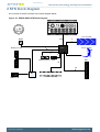
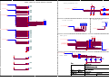
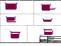
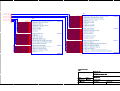
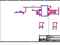
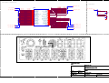
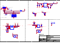
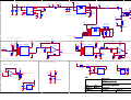
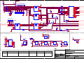
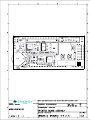
Preliminary
...the world's most energy friendly microcontrollers
USER MANUAL
Starter Kit EFM32-G8XX-STK
Feature rich starter kit for evaluation, prototyping and application development for
the EFM32 Gecko MCU family with the ARM Cortex-M3 CPU core.
Main features;
• Advanced Energy Monitoring provides real-time visibility into the energy
consumption of an application or prototype design.
• On-board debugger with debug out functionality
• 160-segment Energy Micro LCD
Preliminary
...the world's most energy friendly microcontrollers
1 Introduction
1.1 Features
•
•
•
•
•
•
•
•
•
Advanced Energy Monitoring system for precise current tracking.
Special hardware configuration for isolation of the MCU power domain.
Full feature USB debugger with debug out functionality.
160 segment Energy Micro LCD.
20 pin expansion header.
Breakout pads for easy access to I/O pins.
Powered by USB or CR2032 battery.
2 user buttons, 4 user LEDs and touch slider.
32MHz and 32.768kHz crystal oscillators.
2010-04-09 - REVISION
2
www.energymicro.com
Preliminary
...the world's most energy friendly microcontrollers
2 STK block diagram
An overview of the Kit is shown in the block diagram below.
Figure 2.1. EFM32-G8XX-STK Block Diagram
+ 3V
CR2032
Reset
44
4
Debug In/ Out
Touch slider
4
Touch Gecko
EFM3 2
2
4
Push buttons
LEDs
EXP
50
20
BC
USB m ini B
2010-04-09 - REVISION
Breakout pads
3
www.energymicro.com
Preliminary
...the world's most energy friendly microcontrollers
3 Hardware layout
The layout of the EFM32-G8XX-STK is shown below.
Figure 3.1. EFM32-G8XX-STK hardware layout
2010-04-09 - REVISION
4
www.energymicro.com
Preliminary
...the world's most energy friendly microcontrollers
4 Power supply
4.1 USB
The EFM32-G8XX-STK can get its power from the standard USB mini port. The MCU voltage will be
3.15 volts when USB is connected.
4.2 Battery
There is a socket for a 20mm coin cell battery, which can be used to power the kit. When the USB is
disconnected and the battery connect switch is turned on, the EFM and its peripherals is powered by
the battery. The VMCU voltage is 2.85 or lower when powered by the battery, depending on the battery
voltage. There is a 0.15V drop down from the battery voltage. The board controller/AEM is not powered
by the battery, so the BSP software support library cannot be used on battery power.
2010-04-09 - REVISION
5
www.energymicro.com
Preliminary
...the world's most energy friendly microcontrollers
5 Reset infrastructure
5.1 MCU
The primary user reset for the MCU is the reset button on the MCU board. This will only reset the MCU.
The MCU can also be reset by debuggers.
5.2 Board controller
The board controller can only be reset by pulling and reinserting the USB cable.
2010-04-09 - REVISION
6
www.energymicro.com
Preliminary
...the world's most energy friendly microcontrollers
6 Peripherals
The starter kit has a set of peripherals that showcase some of the features of the EFM32G.
Be aware that most EFM I/O routed to peripherals are also routed to the breakout pads. This must be
taken into consideration when using the breakout pads for your application.
6.1 Pushbuttons
The kit has two user pushbuttons marked PB0 and PB1. They are connected to the EFM, and are
debounced by RC filters with a time constant of 1ms.
6.2 LEDs
There are four LEDs on the kit marked LED0 to LED3. An active high on the respective pins will light
the LEDs.
6.3 LCD
An Energy Micro LCD display is connected to the EFM. These lines are not shared on the breakout
pads. Capacitors for the EFM32G LCD boost function is available on the EFM32-G8XX-STK.
6.4 Touch slider
A touch slider utilizing the capacitive touch capability is available. It is placed under the two push buttons
on the kit, above the "TOUCH SLIDER" print.
6.5 Touch Gecko
The Gecko above the pushbuttons, and below the EFM32 logo, can also be used as a capacitive touch
button.
2010-04-09 - REVISION
7
www.energymicro.com
Preliminary
...the world's most energy friendly microcontrollers
7 Advanced Energy Monitor
7.1 Usage
The AEM data is collected by the board controller and can be displayed by a PC application. For instance,
the "Gecko commander" utility contains a "power" command which can dump power data to file. A GUI
application for displaying power usage will be available for download from the Energy Micro download
section later.
7.2 AEM theory of operation
In order to be able to measure currents ranging from 0.1uA to 50mA (114dB dynamic range), two current
sense amplifiers are utilized. The amplifiers measure voltage drop over a small series resistor and
translates this into a current. Each amplifier is adjusted for current measurement in a specific range.
The ranges for the amplifiers overlap and a change between the two occurs when the current is 200uA.
To reduce noise, averaging of the samples is performed before the current measurement is presented
in the AEM GUI.
During startup of the kit, a calibration of the AEM is performed. This calibration compensates for the
offset error in the sense amplifiers.
7.3 AEM accuracy and performance
The Advanced Energy Monitor is capable of measuring currents in the range of 0.1uA to 50mA. For
currents above 200uA, the AEM is accurate within 0.1mA. When measuring currents below 200uA, the
accuracy increases to 1uA. Even though the absolute accuracy is 1uA in the sub 200uA range, the AEM
is able to detect changes in the current consumption as small as 100nA The measurement bandwidth
of the AEM is 60Hz when measuring currents below 200uA and 120Hz when measuring currents above
200uA. The table below summarizes accuracy of the two current sense amplifiers in different ranges.
Table 7.1. AEM accuracy
Current range
Low gain amplifier accuracy
High gain amplifier accuracy
50mA
0.1mA
-
1mA
0.1mA
-
200uA
0.01mA
1uA
10uA
-
0.1uA
1uA
-
0.1uA
Note
Having both USB and battery connected may increase the AEM readings.
2010-04-09 - REVISION
8
www.energymicro.com
Preliminary
...the world's most energy friendly microcontrollers
8 Board controller
The control MCU can act as a board controller (BC). There is a UART connection between the EFM and
the BC. The connection is made by setting the bc_en line high. The EFM can then use the BSP to send
commands to the BC. When bc_en is low, bc_tx and bc_rx can be used by other applications.
To use the board controller for your application, the Board Support Package (BSP) must be installed.
See the BSP chapter to find out how.
Note
The board controller is only available when the STK is powered by USB.
2010-04-09 - REVISION
9
www.energymicro.com
Preliminary
...the world's most energy friendly microcontrollers
9 Board Support Package
The Board Support Package (BSP) is a set of C source and header files that enables easy access to,
and control over some board specific features.
Compared to the Energy Micro development kit, the functionality is limited. Unless you need/want some
of the functions contained in the BSP, there is really no need to include or use it. The EFM32 in the
Starter Kit can be fully usable without BSP support, and you can use all peripherals in the
C:\Program Files\Energy Micro\EFM32 Gecko DK\boards\EFM32_Gxxx_STK\drivers
folder without the BSP.
The BSP use EFM32 peripheral UART0 (TX pin PE0, RX pin PE1) on baudrate 115200-8-N-1 to
communicate with the board controller.
Note
The BSP is only functional when the Starter Kit is USB-powered, using these function calls
under battery power will give unpredictable results.
9.1 Installation location
When installing the complete software package for the kit, the BSP will be installed under the main
installation directory, typically in a location such as
C:\Program Files\Energy Micro\EFM32 Gecko DK\boards\EFM32_Gxxx_STK\bsp\
or something similar (depending on your OS/Windows version). All files in the board support package
is prefixed by stk.
9.2 Application Programming Interface
To use the BSP, include the Starter Kit header file, like this:
#include "stk.h"
All functions in the BSP are prefixed with STK_. The main initialization routine is defined as
void STK_Init(void);
and must be called before any access to the STK-functions. This function call will setup the UART
communication channel with a 115800 baud rate. This baud rate depends on the current core clock, so
correct clock configuration should be set before calling this function.
bool STK_Ready(void);
Returns true if the board controller is responding. A non-responding board will either return false, or
hang (i.e. if the EFM32 is powered by the CR2032 battery cell).
float STK_Current(void);
2010-04-09 - REVISION
10
www.energymicro.com
Preliminary
...the world's most energy friendly microcontrollers
Returns instant current usage in milliamperes.
float STK_Voltage(void);
Returns instant voltage (VMCU) reading in volt.
bool STK_EnergyMode(uint8_t em);
Informs the board controller about the Energy Mode (sleep mode) we are going into. This information
can be used by the board controller to present a richer visual graph for illustrating what the EFM32 is
currently doing.
In addition to these main functions, full documentation of the complete API is included in the Doxygen/
HTML documentation of the installed package.
9.3 Example Applications
Under the EFM32_Gxxx_STK/examples folder in your installation directory, you will find an example
program using the BSP, with corresponding project/Makefiles for the supported IDEs.
9.4 How to include in your own applications
The easiest way to include the BSP in your application is to base your work on the example application
that use the BSP. The following items are recommended for correct configuration:
1. Make sure you define the correct part number (i.e. EFM32G890F128) as a preprocessor defined
symbol
2. Make sure you define the correct part number (i.e. EFM32G890F128) for your project file
3. Add and include the EFM32_CMSIS-files (startup_efm32.s, system_efm32.c, core_cm3.c) to your
project
4. Add and include _all_ BSP package .c-files, with the stk-prefix to your project
5. Configure include paths to point at the CMSIS/CM3/CoreSupport and CMSIS/CM3/DeviceSupport/
EnergyMicro/EFM32 directories
6. Configure include paths to point to the EFM32_Gxxx_STK/bsp directory
Make sure you call "STK_Init()" early at startup, and you should be all set.
9.5 Chip errata
Early versions of the development kit are shipped with EFM32 Engineering Samples on the MCU
modules. There has been updates to configuration and reset values that needs to be configured correctly
on these early parts. We recommend always starting your application with a call to
#include "chip.h"
void CHIP_init(void);
to ensure correct and stable behavior. See the BSP examples for details. We recommend also to
download and read the latest errata from the Energy Micro website for your part number.
2010-04-09 - REVISION
11
www.energymicro.com
Preliminary
...the world's most energy friendly microcontrollers
10 Connectors
10.1 Breakout pads
Most I/O except the LCD pins are routed to the breakout pads at the top and bottom edge of the kit. A
2.54mm (100 mil) pitch pin header can be soldered in place on the pads for easier access.
Note
Some of the breakout pads are shared by on-board EFM peripherals. The shared pins can
be identified by looking at the Shared by column in the tables below. The schematic must
be consulted to make sure that it is OK to use a shared pin in your application.
Table 10.1. Bottom breakout pad row
Pin
Alternative Functions
Shared by
5V
-
-
PA12
TIM2_CC0
LCD Boost capacitor
PA13
TIM2_CC1
LCD Boost capacitor
PA14
TIM2_CC2
LCD Boost capacitor
GND
-
-
PE0
U0_TX/PCNT0_S0
BC_TX
PE1
U0_RX/PCNT0_S1
BC_RX
PE2
ACMP0_O
EXP header
PE3
ACMP1_O
-
GND
-
-
PC0
ACMP0_CH0/US1_TX/PCNT0_S0
User LED 0
PC1
ACMP0_CH1/US1_RX/PCNT0_S1
User LED 1
PC2
ACMP0_CH2/US2_TX
User LED 2
PC3
ACMP0_CH3/US2_RX
User LED 3
PC4
ACMP0_CH4/LET0_O0/US2_CLK/PCNT1_S0
EXP header
PC5
ACMP0_CH5/LET0_O1/US2_CS/PCNT1_S1
EXP header
PC6
ACMP0_CH6/LEU1_TX/I2C0_SDA
-
PC7
ACMP0_CH7/LEU1_RX/I2C0_SCL
-
PC8
ACMP1_CH0/TIM2_CC0/US0_CS
Touch slider segment 0
PC9
ACMP1_CH1/TIM2_CC1/US0_CLK
Touch slider segment 1
PC10
ACMP1_CH2/TIM2_CC2/US0_RX
Touch slider segment 2
PC11
ACMP1_CH3/US0_TX
Touch slider segment 3
PC12
ACMP1_CH4/CMU_OUT0
EXP header
PC13
ACMP1_CH5/TIM1_CC0/TIM0_CDTI0/PCNT0_S0
Touch Gecko
PC14
ACMP1_CH6/TIM1_CC1/TIM0_CDTI1/PCNT0_S1
-
VMCU
-
-
3V3
-
-
2010-04-09 - REVISION
12
www.energymicro.com
Preliminary
...the world's most energy friendly microcontrollers
Table 10.2. Top breakout pad row
Pin
Alternative Functions
Shared by
5V
-
-
PB9
-
User button 0
PB10
-
User button 1
GND
-
-
PB11
DAC_OUT0/LET0_O0
EXP header
PB12
DAC_OUT1/LET0_O1
EXP header
PB15
-
-
GND
-
-
PD0
US1_TX/PCNT2_S0
EXP header
PD1
TIM0_CC0/US1_RX/PCNT2_S1
EXP header
PD2
TIM0_CC1/US1_CLK
EXP header
PD3
TIM0_CC2/US1_CS
EXP header
PD4
LEU0_TX
EXP header
PD5
LEU0_RX
EXP header
GND
-
-
PD6
ACMP0_CH6/LET0_O0/I2C0_SDA
EXP header
PD7
ACMP0_CH7/LET0_O1/I2C0_SCL
EXP header
PD8
ADC0_VCM/CMU_OUT1
EXP header
PD14
I2C0_SDA
-
PD15
I2C0_SCL
-
VMCU
-
-
3V3
-
-
2010-04-09 - REVISION
13
www.energymicro.com
Preliminary
...the world's most energy friendly microcontrollers
10.2 Expansion header
A 20 pin expansion header can be used to connect plugin boards. This contains a selection of I/O plus
powers and ground. See the pinout in the table below.
Table 10.3. Expansion header pinout
I/O
#
#
I/O
GND
1
2
VMCU
PC4
3
4
PD0
PC5
5
6
PD1
PC12
7
8
PD2
PE2
9
10
PD3
PB11
11
12
PD4
PB12
13
14
PD5
PD7
15
16
PD6
PD8
17
18
5V
GND
19
20
3V3
2010-04-09 - REVISION
14
www.energymicro.com
Preliminary
...the world's most energy friendly microcontrollers
10.3 Debug connector
This connector is used for Debug In and Debug Out (see Debug chapter). The pinout is described in
the table.
Table 10.4. Debug connector pinout
Pin
number
Function
Note
1
VTARGET
Target voltage on the debugged application.
2
NC
3
/TRST
4
GND
5
TDI
6
GND
7
TMS/SWDIO
8
GND
9
TCK
10
GND
11
RTCK
12
GND
13
TDO/SWO
14
GND
15
/RESET
16
GND
17
PD
This pin has a 100k pulldown.
18
Cable detect
This signal must be pulled to ground by the external debugger or application for cable
insertion detection.
19
PD
This pin has a 100k pulldown.
20
GND
2010-04-09 - REVISION
JTAG tap reset
JTAG data in
JTAG TMS or Serial Wire data I/O
JTAG TCK or Serial Wire clock
JTAG RTCK
JTAG TDO or Serial Wire Output
Target MCU reset
15
www.energymicro.com
Preliminary
...the world's most energy friendly microcontrollers
11 Debugging
The EFM32-G8XX-STK has an on-board debugger, and it can be used in different ways to debug the
EFM, both on and off kit. Below are descriptions on the different modes. Check the configuration chapter
to find out how to change the debug setting.
Table 11.1. Debug modes
Mode
Description
Debug MCU
In this mode the on-board debugger is connected to EFM on the EFM32-G8XX-STK.
Debug IN
In this mode the on-board debugger is disconnected, and an external debugger can be connected to
debug the EFM on the EFM32-G8XX-STK.
Debug OUT
In this mode the on-board debugger can be used to debug an EFM mounted in your own application.
11.1 Debugging during battery operation
When the EFM is powered by the battery (i.e. the USB is disconnected), the on-board debug functionality
is not available. To enable debugging in this mode, connect an external debugger (e.g. another EFM32G8XX-STK) to the debug pads in the bottom right corner of the EFM32-G8XX-STK. These pads are
connected directly to the EFM32 debug interface.
Note
When the on-board debugger is active, a current of approximately 1.6uA will be added to the
AEM measurements.
2010-04-09 - REVISION
16
www.energymicro.com
Preliminary
...the world's most energy friendly microcontrollers
12 IDEs
The Energy Micro software packages contains various examples in source form to use with the Starter
Kit. The following IDEs are supported.
12.1 IAR Embedded Workbench for ARM
An evaluation version of IAR Embedded Workbench for ARM is included on a CD in the EFM32-G8XXSTK package. Check the quick start guide for where to find updates, and IAR's own documentation on
how to use it. You will find the IAR project file in the
iar
subfolder of each project
12.2 Rowley Associates - CrossWorks for ARM
See the quick start guide for download details for CrossWorks for ARM. You will find CrossWorks project
files in the
rowley
subfolder of each project.
12.3 CodeSourcery - Sourcery G++
See the quick start guide for download details for Sourcery G++. The
codesourcery
subfolder contains Makefiles for use with the Sourcery G++ development environment.
12.4 Keil - MDK-ARM
See the quick start guide for download details for evaluation versions of Keil MDK-ARM. The
arm
subfolder in each project contains project files for MDK-ARM. Please see the MDK-ARM documentation
for usage details.
2010-04-09 - REVISION
17
www.energymicro.com
Preliminary
...the world's most energy friendly microcontrollers
13 Gecko Commander and Upgrades
Gecko Commander is a command line utility that comes with the Gecko DK Installer package. It can
perform various kit and EFM32 specific tasks. Press "h" for help at the prompt for a listing of available
commands. Press "h command" for help for a specific command, listing arguments and options.
13.1 Available commands
Table 13.1. Gecko Commander
Command
Description
ping
"Ping" kit, i.e. verify that target kit is up and running
speed
Sets the link speed for the serial wire debug interface from the kit, towards the EFM32
reset
Reset kit, which also implies a reset of the EFM32 as well
usb
Change J-Link USB port used, default is port 0. Unless you have multiple J-Link debuggers there
should be no reason to change this
version
Get PCB and firmware versions of kit
install
Install an application or boot package. This command, with a filename ending with .emz as an option
upgrades the kit software
ls
List directory, shows which binary files has been uploaded to the kit, which can be flashed with the GUI
put
Copy a binary file from host to target, that can be used to flash directly from the kit GUI (Flash
submenu)
rm
Remove file
flash
Flashes the EFM32 program memory with binary file, starting from flash address 0x0000000. Enter
filename as argument.
verify
Verifies correct installation of a binary into flash
dumpbin
Dumps content of memory of the EFM32 to file
erase
Erases the entire flash
unlock
Unlocks a locked chip and performs a device erase
lock
Locks the chip, prevents reading out the flash over debugger interface
protect
Write-protects pages in flash
uprotect
Clears all write protection lock bits
power
Dump power measurements from the running application to file. Enter filename as argument.
mode
Sets the mode of the on-board debugger. Available modes:
mcu - Debug the EFM32 using the on-board debugger
in - Debug the EFM32 using an external debugger
out - Use the STK as an external debugger
off - Disable the debugger
13.2 Upgrades
Upgrading the kit can be done by using the "Upgrade Kit" script in the start menu. New versions can
be downloaded from http://www.energymicro.com/downloads/. The script will use Gecko commander to
install the latest available Kit SW package. It is important to upgrade the kit when installing a new SW
package, as new Gecko commander functionality might require kit controller software upgrades.
2010-04-09 - REVISION
18
www.energymicro.com
Preliminary
...the world's most energy friendly microcontrollers
14 Version information
The current version information can be read from Gecko Commander.
Table 14.1. Current versions
Type
Version
Released
Firmware revision
1v0
2010-04-09
Hardware version
1v0
2010-04-09
2010-04-09 - REVISION
19
www.energymicro.com
Preliminary
...the world's most energy friendly microcontrollers
15 Schematic
On the next pages you can find the schematic and the assembly drawings of the main board.
2010-04-09 - REVISION
20
www.energymicro.com
5
4
3
2
1
D
D
EFM32 Starter Kit
Board Function
Top Level Schematic
Revision History
Page
Rev.
1
2
Description
A
A lot of bug fixes and improvements.
A1
Added #RST to the debug header and
added a separate header (J100) for
the touch segment pins.
3
4
C
C
5
A2
Fixed renaming of 3V3 to PCB_REV0
A3
Swapped two pins on D600 to
simplify routing.
B
B
/
TOP
Schematic Title
A
A
EFM32 Starter Kit
Page Title
Designed:
Approved:
GB
Size
A3
<OrgAddr2>
BOM Doc No:
<Cage Code>
Design Created Date:
W ednesday, December 03, 2008
Title Page
Document number
Revision
BRD2001
Sheet Created Date
Saturday, March 21, 2009
A3
Sheet Modified Date
W ednesday, March 03, 2010
Sheet
1 of
10
5
4
3
2
TODO: Hide TP values before release
1
User pushbuttons
(p 4,6) MCU_PA[15..0]
VMCU
MCU_PA12
MCU_PA13
MCU_PA14
TP100
TP101
TP102
SW 100
4,5,6)
D
R101
100K
UIF_PB[1..0]
(p 4) UIF_PB[1..0]
MCU_PB[15..0]
MCU_PB9
MCU_PB10
MCU_PB11
MCU_PB12
R102
100K
UIF_PB0
UIF_PB1
TP146
TP145
TP103
TP104
TP148
R100
100R
1
3
2
4
GND
C100
C101
10N
10N
D
SW 101
1
3
2
4
R103
100R
MCU_PB15
3,4,9) MCU_PC[15..0]
GND
MCU_PC0
MCU_PC1
MCU_PC2
MCU_PC3
MCU_PC4
MCU_PC5
MCU_PC6
MCU_PC7
MCU_PC8
MCU_PC9
MCU_PC10
MCU_PC11
MCU_PC12
MCU_PC13
MCU_PC14
TP105
TP106
TP107
TP108
TP109
TP110
TP111
TP112
J100
1
2
3
4
5
GND
GND
Touch gecko
Touch slider
T101 TOUCH GECKO
T100 TOUCH SLIDER
TP115
NM
TP117
(p 4) UIF_SLIDER[3..0]
UIF_SLIDER0
UIF_SLIDER1
UIF_SLIDER2
UIF_SLIDER3
C
(p 4,6) MCU_PD[15..0]
MCU_PD0
MCU_PD1
MCU_PD2
MCU_PD3
MCU_PD4
MCU_PD5
MCU_PD6
MCU_PD7
MCU_PD8
TP118
TP119
TP120
TP121
TP122
TP123
TP124
TP125
TP126
MCU_PD14
MCU_PD15
TP127
TP128
MCU_PE0
MCU_PE1
MCU_PE2
MCU_PE3
TP129
TP130
TP131
TP132
(p 4,6) MCU_PE[15..0]
EXP port
VMCU 5V
1
3
5
7
9
11
13
15
17
19
MCU_PC4
MCU_PC5
MCU_PC12
MCU_PE2
MCU_PB11
MCU_PB12
MCU_PD7
MCU_PD8
(p 4) MCU_PE2
(p 4) MCU_PB11
(p 4) MCU_PB12
TP133
TP134
TP135
TP136
TP137
TP138
GND
3V3
P100
(p 3,4,9) MCU_PC[15..0]
B
C
UIF_GECKO
2
4
6
8
10
12
14
16
18
20
MCU_PD0
MCU_PD1
MCU_PD2
MCU_PD3
MCU_PD4
MCU_PD5
MCU_PD6
HEADER_2X10_2.54MM_HOR_SMD
B
MCU_PD[15..0]
GND
(p 4,6)
(p 4) UIF_LED[3..0]
RP100
3V3
TP141
TP142
/
TOP
LED101
YELLOW
1
1
LED100
YELLOW
2
LED102
YELLOW
LED103
YELLOW
1
2K2
1
TP139
TP140
2
4
3
2
1
2
User LEDs
VMCU
5
6
7
8
2
UIF_LED0
UIF_LED1
UIF_LED2
UIF_LED3
GND
Schematic Title
A
5V
A
EFM32 Starter Kit
TP143
TP144
Page Title
Designed:
Approved:
GB
Size
A3
<OrgAddr2>
BOM Doc No:
<Cage Code>
Design Created Date:
W ednesday, December 03, 2008
User Interfaces
Document number
Revision
BRD2001
Sheet Created Date
Saturday, March 21, 2009
A3
Sheet Modified Date
W ednesday, March 03, 2010
Sheet
2 of
10
5
4
3
PA Connections
(p 2,4,6) MCU_PA[15..0]
LCD_PA[15..0]
MCU_PA0
MCU_PA1
MCU_PA2
MCU_PA3
MCU_PA4
MCU_PA5
MCU_PA6
MCU_PA7
MCU_PA8
MCU_PA9
MCU_PA10
MCU_PA11
MCU_PA12
MCU_PA13
MCU_PA14
MCU_PA15
D
2
1
PB Connections
(p 2,4,6)
LCD_PA0
LCD_PA1
LCD_PA2
LCD_PA3
LCD_PA4
LCD_PA5
LCD_PA6
LCD_PA7
LCD_PA8
LCD_PA9
LCD_PA10
LCD_PA11
LCD_PA12
LCD_PA13
LCD_PA14
LCD_PA15
(p 2,4,5,6) MCU_PB[15..0]
LCD_PB[6..0]
MCU_PB0
MCU_PB1
MCU_PB2
MCU_PB3
MCU_PB4
MCU_PB5
MCU_PB6
(p 4,6)
LCD_PB0
LCD_PB1
LCD_PB2
LCD_PB3
LCD_PB4
LCD_PB5
LCD_PB6
D
MCU_PB7
MCU_PB8
MCU_PB9
MCU_PB10
LFXTAL_P
LFXTAL_N
(p 4,5)
(p 4,5)
HFXTAL_P
HFXTAL_N
(p 4,5)
(p 4,5)
UIF_PB[1..0]
(p 2,4)
UIF_PB0
UIF_PB1
MCU_PB13
MCU_PB14
PC Connections
C
PD Connections
(p 2,4,9) MCU_PC[15..0]
UIF_LED[3..0]
MCU_PC0
MCU_PC1
MCU_PC2
MCU_PC3
MCU_PC8
MCU_PC9
MCU_PC10
MCU_PC11
UIF_LED0
UIF_LED1
UIF_LED2
UIF_LED3
UIF_SLIDER[3..0]
(p 2,4)
(p 2,4,6) MCU_PD[15..0]
UIF_SLIDER0
UIF_SLIDER1
UIF_SLIDER2
UIF_SLIDER3
MCU_PC13
LCD_PD[12..9]
MCU_PD9
MCU_PD10
MCU_PD11
MCU_PD12
UIF_GECKO
MCU_PC15
C
(p 2,4)
(p 4,9)
(p 4,6)
LCD_PD9
LCD_PD10
LCD_PD11
LCD_PD12
MCU_PD13
EFM_BC_EN
MCUDBG_TDO_SW O (p 4,9)
PF Connections
B
B
(p 4,6,9) MCU_PF[9..0]
MCU_PF0
MCU_PF1
MCUDBG_TCK_SW CLK (p 4,9)
MCUDBG_TMS_SW DIO (p 4,9)
PE Connections
LCD_PF[9..2]
(p 4,6)
(p 2,4,6) MCU_PE[15..0]
MCU_PE0
MCU_PE1
EFM_BC_TX
EFM_BC_RX
LCD_PE[15..4]
A
MCU_PE4
MCU_PE5
MCU_PE6
MCU_PE7
MCU_PE8
MCU_PE9
MCU_PE10
MCU_PE11
MCU_PE12
MCU_PE13
MCU_PE14
MCU_PE15
MCU_PF2
MCU_PF3
MCU_PF4
MCU_PF5
MCU_PF6
MCU_PF7
MCU_PF8
MCU_PF9
LCD_PE4
LCD_PE5
LCD_PE6
LCD_PE7
LCD_PE8
LCD_PE9
LCD_PE10
LCD_PE11
LCD_PE12
LCD_PE13
LCD_PE14
LCD_PE15
(p 4,6)
LCD_PF2
LCD_PF3
LCD_PF4
LCD_PF5
LCD_PF6
LCD_PF7
LCD_PF8
LCD_PF9
<Schematic Path>
TOP
Schematic Title
A
EFM32 Starter Kit
Page Title
Designed:
Approved:
GB
Size
A3
<OrgAddr2>
BOM Doc No:
<Cage Code>
Design Created Date:
W ednesday, December 03, 2008
Signal Assignments
Document number
Revision
BRD2001
Sheet Created Date
Friday, January 15, 2010
A3
Sheet Modified Date
W ednesday, March 03, 2010
Sheet
3 of
10
5
4
3
2
1
D
D
(p 2,6) MCU_PA[15..0]
U300A
(p 2,5,6) MCU_PB[15..0]
(p 2,3,9) MCU_PC[15..0]
(p 2,6) MCU_PD[15..0]
U300B
(p 2,6) MCU_PE[15..0]
(p 6,9) MCU_PF[9..0]
C
B
MCU_PD0
MCU_PD1
MCU_PD2
MCU_PD3
MCU_PD4
MCU_PD5
MCU_PD6
MCU_PD7
MCU_PD8
MCU_PD9
MCU_PD10
MCU_PD11
MCU_PD12
MCU_PD13
MCU_PD14
MCU_PD15
L11
K11
J9
J10
J11
H9
H10
H11
H8
D6
A5
B5
C5
C4
H3
J3
MCU_PE0
MCU_PE1
MCU_PE2
MCU_PE3
MCU_PE4
MCU_PE5
MCU_PE6
MCU_PE7
MCU_PE8
MCU_PE9
MCU_PE10
MCU_PE11
MCU_PE12
MCU_PE13
MCU_PE14
MCU_PE15
E9
E10
F10
E11
A9
B9
C9
D9
B4
A4
C3
B3
A3
B2
A2
A1
MCU_PF0
MCU_PF1
MCU_PF2
MCU_PF3
MCU_PF4
MCU_PF5
MCU_PF6
MCU_PF7
MCU_PF8
MCU_PF9
E8
D8
C8
B8
A8
A7
B7
A6
B6
C6
D0 / USART1_TX #1 / PCNT2_S0IN #0 / ADC0_CH0
D1 / TIMER0_CC0 #3 / USART1_RX #1 / PCNT2_S1IN #0 / ADC0_CH1
D2 / TIMER0_CC1 #3 / USART1_CLK #1 / ADC0_CH2
D3 / TIMER0_CC2 #3 / USART1_CS #1 / ADC0_CH3
D4 / LEUART0_TX #0 / ADC0_CH4
D5 / LEUART0_RX #0 / ADC0_CH5
D6 / LETIMER0_OUT0 #0 / I2C0_SDA #1 / ADC0_CH6
D7 / LETIMER0_OUT1 #0 / I2C0_SCL #1 / ADC0_CH7
D8 / CMU_CLKOUT1 #1 / ADC0_VCM
D9 / EBI_CS0 / LCD_SEG28
D10 / EBI_CS1 / LCD_SEG29
D11 / EBI_CS2 / LCD_SEG30
D12 / EBI_CS3 / LCD_SEG31
D13
D14 / I2C0_SDA #3
D15 / I2C0_SCL #3
E0 / UART0_TX #1 / PCNT0_S0IN #1
E1 / UART0_RX #1 / PCNT0_S1IN #1
E2 / ACMP0 _OUT #1
E3 / ACMP1_OUT #1
E4 / USART0_CS #1 / LCD_COM0
E5 / USART0_CLK #1 / LCD_COM1
E6 / USART0_RX #1 / LCD_COM2
E7 / USART0_TX #1 / LCD_COM3
E8 / EBI_AD0 / PCNT2_S0IN #1 / LCD_SEG4
E9 / EBI_AD1 / PCNT2_S1IN #1 / LCD_SEG5
E10 / EBI_AD2 / TIMER1_CC0 #1 / USART0_TX #0 / LCD_SEG6
E11 / EBI_AD3 / TIMER1_CC1 #1 / USART0_RX #0 / LCD_SEG7
E12 / EBI_AD4 / TIMER1_CC2 #1 / USART0_CLK #0 / LCD_SEG8
E13 / EBI_AD5 / USART0_CS #0 / ACMP0_OUT #0 / LCD_SEG9
E14 / EBI_AD6 / LEUART0_TX #2 / LCD_SEG10
E15 / EBI_AD7 / LEUART0_RX #2 / LCD_SEG11
F0 / LETIMER0_OUT0 #2 / DBG_SWCLKTCK
F1 / LETIMER0_OUT1 #2 / DBG_SWDITMS
F2 / EBI_ARDY / ACMP1_OUT #0 / DBG_SWV #0 / LCD_SEG0
F3 / TIMER0_CCC0 #2 / EBI_ALE / LCD_SEG1
F4 / TIMER0_CCC1 #2 / EBI_WEn / LCD_SEG2
F5 / TIMER0_CCC2 #2 / EBI_REn / LCD_SEG3
F6 / TIMER0_CC0 #2 / UART0_TX #0 / LCD_SEG24
F7 / TIMER0_CC1 #2 / UART0_RX #0 / LCD_SEG25
F8 / TIMER0_CC2 #2 / LCD_SEG26
F9 / LCD_SEG27
PORT D
PORT E
PORT F
MCU_PA0
MCU_PA1
MCU_PA2
MCU_PA3
MCU_PA4
MCU_PA5
MCU_PA6
MCU_PA7
MCU_PA8
MCU_PA9
MCU_PA10
MCU_PA11
MCU_PA12
MCU_PA13
MCU_PA14
MCU_PA15
C2
C1
D2
D1
E3
E2
E1
H4
H5
J5
J6
K5
J4
K3
L3
B1
MCU_PB0
MCU_PB1
MCU_PB2
MCU_PB3
MCU_PB4
MCU_PB5
MCU_PB6
MCU_PB7
MCU_PB8
MCU_PB9
MCU_PB10
MCU_PB11
MCU_PB12
MCU_PB13
MCU_PB14
MCU_PB15
E4
F1
F2
F3
F4
G1
G2
K1
L1
J7
J8
L5
L6
L8
L9
D3
MCU_PC0
MCU_PC1
MCU_PC2
MCU_PC3
MCU_PC4
MCU_PC5
MCU_PC6
MCU_PC7
MCU_PC8
MCU_PC9
MCU_PC10
MCU_PC11
MCU_PC12
MCU_PC13
MCU_PC14
MCU_PC15
H1
J1
H2
J2
K2
L2
G10
G11
D10
D11
C10
C11
B10
B11
A10
A11
A0 / TIMER0_CC0 #0,1 / EBI_AD9 / I2C0_SDA #0 / LCD_SEG13
A1 / TIMER0_CC1 #0,1 / CMU_CLKOUT1 / EBI_AD10 / I2C0_SCL #0 / LCD_SEG14
A2 / TIMER0_CC2 #0,1 / CMU_CLKOUT0 / EBI_AD11 / LCD_SEG15
A3 / TIMER0_CCC0 #0 / EBI_AD12 / UART0_TX #2 / LCD_SEG16
A4 / TIMER0_CCC1 #0 / EBI_AD13 / UART0_RX #2 / LCD_SEG17
A5 / TIMER0_CCC2 #0 / EBI_AD14 / LEUART1_TX #1 / LCD_SEG18
A6 / EBI_AD15 / LEUART1_RX #1 / LCD_SEG19
A7 / LCD_SEG35
A8 / TIMER2_CC0 #0 / LCD_SEG36
A9 / TIMER2_CC1 #0 / LCD_SEG37
A10 / TIMER2_CC2 #0 / LCD_SEG38
A11 / LCD_SEG39
A12 / TIMER2_CC0 #1 / LCD_BCAP_P
A13 / TIMER2_CC1 #1 / LCD_BCAP_N
A14 / TIMER2_CC2 #1 / LCD_BEXT
A15 / EBI_AD8 / LCD_SEG12
B0 / TIMER1_CC0 #2 / LCD_SEG32
B1 / TIMER1_CC1 #2 / LCD_SEG33
B2 / TIMER1_CC2 #2 / LCD_SEG34
B3 / USART2_TX #1 / PCNT1_S0IN #1 / LCD_SEG20
B4 / USART2_RX #1 / PCNT1_S1IN #1 / LCD_SEG21
B5 / USART2_CLK #1 / LCD_SEG22
B6 / USART2_CS #1 / LCD_SEG23
B7 / USART1_CLK #0/ LFXTAL_P
B8 / USART1_CS #0 / LFXTAL _N
B9
B10
B11 / LETIMER0_OUT0 #1 / DAC0_OUT0
B12 / LETIMER0_OUT1 #1 / DAC0_OUT1
B13 / LEUART0_TX #1 / HFXTAL_P
B14 / LEUART0_RX #1 / HFXTAL_N
B15
PORT A
PORT B
C
C0 / USART1_TX #0 / PCNT0_S0IN #2 / ACMP0_CH0
C1 / USART1_RX #0 / PCNT0_S1IN #2 / ACMP0_CH1
C2 / USART2_TX #0 / ACMP0_CH2
C3 / USART2_RX #0 / ACMP0_CH3
C4 / USART2_CLK #0 / LETIMER_OUT0 #3 / PCNT1_S0IN #0 / ACMP0_CH4
C5 / USART2_CS #0 / LETIMER_OUT1 #3 / PCNT1_S1IN #0 / ACMP0_CH5
C6 / LEUART1_TX #0 / I2C0_SDA #2 / ACMP0_CH6
C7 / LEUART1_RX #0 / I2C0_SCL #2 / ACMP0_CH7
C8 / TIMER2_CC0 #2 / USART0_CS #2 / ACMP1_CH0
C9 / TIMER2_CC1 #2 / USART0_CLK #2 / ACMP1_CH1
C10 / TIMER2_CC2 #2 / USART0_RX #2 / ACMP1_CH2
C11 / USART0_TX #2 / ACMP1_CH3
C12 / CMU_CLKOUT0 #1 / ACMP1_CH4
C13 / TIMER0_CCC0 #1,3 / TIMER1_CC0 #0 / PCNT0_S0IN #0 / ACMP1_CH5
C14 / TIMER0_CCC1 #1,3 / TIMER1_CC1 #0 / UART0_TX #3 / PCNT0_S1IN #0 / ACMP1_CH6
C15 / TIMER0_CCC2 #1,3 / TIMER1_CC2 #0 / UART0_RX #3 / DBG_SWV #1 / ACMP1_CH7
PORT C
B
EFM32G890F128
EFM32G890F128
<Schematic Path>
TOP
Schematic Title
A
A
EFM32 Starter Kit
Page Title
Designed:
Approved:
GB
Size
A3
<OrgAddr2>
BOM Doc No:
<Cage Code>
Design Created Date:
W ednesday, December 03, 2008
EFM32 I/O
Document number
Revision
BRD2001
Sheet Created Date
Tuesday, January 12, 2010
A3
Sheet Modified Date
W ednesday, March 03, 2010
Sheet
4 of
10
5
4
3
2
D
TP400
1
D
U300C
DECOUPLING
F11
C400
K6
(p 9) MCUDBG_#RESET
VMCU
RESETn
1U
VDD_DREG
VMCU
K8
K9
L10
L400
1
SW 400
R401
100R
VDD
VDD
VDD
VDD
VDD
VDD
TP401
2
AVDDU1
AVDD
AVDD
AVDD
F8
D5
D7
G8
H7
L4
G4
GND
VDDU1
BLM21B102S R400 1R
C401 C402 C403 C404 C405 C406
1
3
2
4
C407
C409 C410 C411
VSS
C408
100N
GND
10U
10N
L7
K7
K10
GND
C
VSS
VSS
VSS
VSS
VSS
VSS
10N
AVSS
AVSS
AVSS
F9
100N 100N 100N 100N 100N 100N
10U
D4
C7
G9
H6
K4
G3
GND
C
EFM32G890F128
GND
GND
Low Frequency Clock
HFXTAL_N
(p 4)
LFXTAL_N
(p 4)
HFXTAL_P
(p 4)
LFXTAL_P
(p 4)
X400
B
1
C412
12P
X401
2
2
32.0MHz
C413
12P
B
1
32.768kHz
C414
22P
GND
C415
22P
GND
GND
GND
/
TOP
Schematic Title
A
A
EFM32 Starter Kit
Page Title
Designed:
Approved:
GB
Size
A3
<OrgAddr2>
BOM Doc No:
<Cage Code>
Design Created Date:
W ednesday, December 03, 2008
EFM32 Power
Document number
Revision
BRD2001
Sheet Created Date
Tuesday, January 12, 2010
A3
Sheet Modified Date
W ednesday, March 03, 2010
Sheet
5 of
10
5
4
3
2
1
LCD signal connections
LCD Boost
(p 4) LCD_PF[9..2]
D
(p 4) LCD_PE[15..4]
LCD500
LCD_PF2
LCD_PF3
LCD_PF4
LCD_PF5
LCD_PE8
LCD_PE9
LCD_PE10
LCD_PE11
LCD_PE12
LCD_PE13
LCD_PE14
LCD_PE15
LCD_PA15
LCD_PA0
LCD_PA1
LCD_PA2
LCD_PA3
LCD_PA4
LCD_PA5
LCD_PA6
LCD_PB3
LCD_PB4
LCD_PB5
LCD_PB6
(p 2,4) LCD_PA[15..0]
LCD_SEG0
LCD_SEG1
LCD_SEG2
LCD_SEG3
LCD_SEG4
LCD_SEG5
LCD_SEG6
LCD_SEG7
LCD_SEG8
LCD_SEG9
LCD_SEG10
LCD_SEG11
LCD_SEG12
LCD_SEG13
LCD_SEG14
LCD_SEG15
LCD_SEG16
LCD_SEG17
LCD_SEG18
LCD_SEG19
LCD_SEG20
LCD_SEG21
LCD_SEG22
LCD_SEG23
1
2
3
4
5
6
7
8
9
10
11
12
13
14
15
16
17
18
19
20
21
22
23
24
A0_EM2_EM3_EM4
COM3
A1_EM0_EM1_ANT
COM2
A2_7C_7M_7B
COM1
A3_7E_7G_7F
COM0
A4_6C_6M_6B
COL10_8E_8G_8F
A5_6E_6G_6F
8D_8C_8B_8A
A6_5C_5M_5B
NC
A7_5E_5G_5F
DP10_9E_9G_9F
EFM_PAD0_PAD1_GEK
9D_9C_9B_9A
MINUS_1E_1G_1F
NC
1D_1Q_1H_1A
NC
1N_1P_1J_1K
DP2_DP3_DP4_DP5
BAT_1C_1M_1B
PM_10E_10G_10F
B2_2E_2G_2F
C_F_UA_MA
2D_2Q_2H_2A
10D_10C_10B_10A
2N_2P_2J_2K
AM_11E_11G_11F
COL3_2C_2M_2B
11D_11C_11B_11A
B0_3E_3G_3F
7N_7P_7J_7K
3D_3Q_3H_3A
7D_7Q_7H_7A
3N_3P_3J_3K
6N_6P_6J_6K
B1_3C_3M_3B
6D_6Q_6H_6A
DP6_4E_4G_4F
5N_5P_5J_5K
4D_4Q_4H_4A
5D_5Q_5H_5A
4N_4P_4J_4K
COL5_4C_4M_4B
EM LCD
(p 4) LCD_PB[6..0]
48
47
46
45
44
43
42
41
40
39
38
37
36
35
34
33
32
31
30
29
28
27
26
25
LCD_COM3
LCD_COM2
LCD_COM1
LCD_COM0
LCD_PE7
LCD_PE6
LCD_PE5
LCD_PE4
LCD_SEG39
LCD_SEG38
LCD_SEG36
LCD_SEG35
LCD_PA11
LCD_PA10
LCD_PA8
LCD_PA7
LCD_PE[15..4]
(p 4)
LCD_PA[15..0]
(p 2,4)
(p 2,4) LCD_PA[15..0]
D
LCD_PA12
LCD_PA9
C500
22N
LCD_PA13
LCD_PA14
LCD_SEG34
LCD_SEG33
LCD_SEG32
C501
1U
LCD_PB2
LCD_PB1
LCD_PB0
GND
LCD_SEG31
LCD_SEG30
LCD_SEG29
LCD_SEG28
LCD_PD12
LCD_PD11
LCD_PD10
LCD_PD9
LCD_SEG27
LCD_SEG26
LCD_SEG25
LCD_SEG24
LCD_PF9
LCD_PF8
LCD_PF7
LCD_PF6
LCD_PB[6..0]
(p 4)
LCD_PD[12..9]
LCD_PF[9..2]
C
(p 4)
(p 4)
C
Segment names
B
B
<Schematic Path>
TOP
Schematic Title
A
A
EFM32 Starter Kit
Page Title
Designed:
Approved:
GB
Size
A3
<OrgAddr2>
BOM Doc No:
<Cage Code>
Design Created Date:
W ednesday, December 03, 2008
LCD
Document number
Revision
BRD2001
Sheet Created Date
Tuesday, January 12, 2010
A3
Sheet Modified Date
W ednesday, March 03, 2010
Sheet
6 of
10
5
4
3
2
1
5V
TP600
3V3
U600
2
IN
OUT1
OUT2
R600
10K
D
C600
C601
100N
10U
4
1 2 3 x 4
GND
FAULT
TP604
GND
GND
GND_HEAT
CC
LP3982ILD-ADJ
GND
R601
180K
D
8
6
R602
110K
C602
33N
Place these TPs
close to USB
header
5V
5
3
6
7
2
8
9
5
SHDN
3
9
P600
USB_MINI_B
1
SET
7
1
4
GND
GND
TP603
GND
GND
L600
GND
1
2
3V3
BLM41P600S
R603
100K
5V
6
5
USBDP
(p 10)
USBDM
(p 10)
R604
100K
(p 10)
R606
100K
(p 10)
C603
R605
100K
C604
4
D600
TP601 TP602
3V3_SENSE
5V_SENSE
100N
100N
IP4220CZ6
C
C
GND
GND
1
2
3
Power input
GND
3V3 3V3
M1
3V3
VMCU
VMCU_DBG
R607
1K
VMCU_AEM
R608
1K
M2
M3
3V3
U601A
U602A
B
2
4
9
10
EFM_BC_RX
EFM_BC_TX
R612
1M
13
5
6
12
COM1
COM2
COM3
COM4
(p 10) CTRLMCU_I2C_SDA
(p 10) CTRLMCU_I2C_SCL
TS3A4751
NO1
NO2
NO3
NO4
5
6
1
3
8
11
BC_RX
BC_TX
1
2
3
(p 10)
(p 10)
SDA
SCL
R609
10K
GND
A0
A1
A2
7
WP
EEPROM_W P
B
(p 10)
24AA024
IN1
IN2
IN3
IN4
GND
3V3
EFM_BC_EN
U601B
R611
10M
C605
100N
R610
10M
4
VCC
8
VSS
24AA024
GND
GND
VMCU
GND
U602B
14
A
C606
V+
<Schematic Path>
TOP
Schematic Title
100N
GND
7
A
EFM32 Starter Kit
TS3A4751
Page Title
GND
Designed:
Approved:
GB
Size
A3
<OrgAddr2>
BOM Doc No:
<Cage Code>
Design Created Date:
W ednesday, December 03, 2008
Power + Misc
Document number
Revision
BRD2001
Sheet Created Date
Saturday, March 21, 2009
A3
Sheet Modified Date
W ednesday, March 03, 2010
Sheet
7 of
10
5
4
3
2
(p 10) AEM_VMCU_ENABLE
TP702
VMCU_R
VMCU_S
TP700
TP701
TP709
U700
U701
2
IN
OUT1
OUT2
R700
10K
C702
100N
D
7
C703
GND
FAULT
GND
GND_HEAT
CC
LP3982ILD-ADJ
GND
1
4
4
4R7
5
C700
10U
COM
D700
R725
1
NO
100N
2
1
0R
IN
NM
ST700
2
GND
GND
TP703 VMCU
5
V+
8
GND
3
NC
C701
6
R702
180K
SHDN
10U
3
9
GND
SET
R701
1
D
2
6
TS5A3159A
R703
110K
C705
33N
C704
100N
100mA calibration switch
100N
0R
D701
TP715
2
GND
GND
GND
1
GND
C706
R704
1
5V
1
5V
SW 700
TP704
1 2
ON
TP705
TP712
TP714
TP711
TP713
+
TS3A4751
2
4
9
10
COM1
COM2
COM3
COM4
AEM_CTRL0 13
5
AEM_CTRL1
6
AEM_CTRL2
AEM_CTRL3 12
1
3
8
11
NO1
NO2
NO3
NO4
GND
IN1
IN2
IN3
IN4
C
P700
COIN_CELL
2
U702A
R705
1K
R706
22K
R707
47K
R708
1M
C
(p 10) AEM_CTRL[3..0]
MCU power regulators
GND
3
5
9
R717
1R
C714
10U
IN+
R714
10K
10K
3
C712
VREG
V+
C711
100N
1
2
OUT
4
GND
U704A
3
5
9
R719
AEM_SENSE_CURRENT_RANGE1
R712
0R
LTC6102CDD
-INS
-INF
IN+
R715
R716
10K
10K
TLV272
5
C713
1N
VVV- (HEAT)
OUT
(p 10)
4
U704B
D702
BAT54S
NM
2
GND
R721
0R
R723
1K
NM
GND
AEM_SENSE_CURRENT_RANGE2
GND
GND
GND
ADC referance voltage
7
TP707
6
GND
3
R720
10K
R722
1K
NM
1N
8
VREG
V+
0R
GND
B MCU power current sense
1
2
6
7
TP706
1N
VVV- (HEAT)
R718
12K
GND
R711
4R7
U705
TLV272
1
1
BLM21B102S
-INS
-INF
8
R713
-
6
7
1N
R710
43R
LTC6102CDD
1
2
1
2
C710
100N
L700
5V
U703
C709
VCS
+
R709
1K8
VMCU_S
-
VCS
VMCU_R
2
VMCU_S
+
VMCU_R
C708
(p 10)
B
GND
5V
L701
VMCU voltage sense
1
3V3
2
R724
1R
BLM21B102S
U704C
TP708
C716
U706A
4
-
ADC_VREF
VMCU_AEM
1
1
4
AEM_SENSE_VOLTAGE (p 10)
R728
1K
TP710
+
C719
3V3
D703
2
VDD
2
GND
A
Page Title
5
Approved:
GB
MCP6001T
GND
EFM32 Starter Kit
GND
Designed:
GND
7
Schematic Title
LM4040CIM3-3.0
U706B
C720
100N
100N
GND
/
TOP
A
GND
V+
TLV272
10U
GND
C707
U702B
14
GND
GND
1N
MCP6001T
8
TS3A4751
C718
1
R729
100K
VDD
1U
R727
47K
3
C715
100N
3V3
Size
A3
<OrgAddr2>
BOM Doc No:
<Cage Code>
Design Created Date:
W ednesday, December 03, 2008
Advanced Energy Monitor
Document number
Revision
BRD2001
Sheet Created Date
W ednesday, August 19, 2009
A3
Sheet Modified Date
W ednesday, March 03, 2010
Sheet
8 of
10
5
3V3
4
3
DEBUG_EXT_CABLE_ATTACH (p 10)
R800
10K
2
1
TP801
TP802
TP809
TP808
TP804
TP810
TP800
TP807
TP803
VTARGET
P800
74LVC4066
2
4
6
8
10
12
14
16
18
20
D
1
3
5
7
9
11
13
15
17
19
2
3
9
10
DH_VTARGET
DH_#TRST
DH_TDI
DH_TMS_SW DIO
DH_TCK_SW CLK
DH_RTCK
DH_TDO_SW O
DH_#RESET
1
TP806
2
3
4
5
6
7
R802
100K
R803
100K
1Z
2Z
3Z
4Z
1
4
8
11
1Y
2Y
3Y
4Y
8
RP800
2
3
5
6
8
9
11
12
13
14
16
17
19
20
22
23
33R
RP801
1
2
3
4
R801
47K
8
7
6
5
SW _TDO_SW O
33R
74LVC4066
9
GNDGND
U801A
8
7
6
5
VTARGET
R804
100K
D800
VESD05A8A-HNH
1
2
3
4
SW _#TRST
SW _TDI
SW _TMS_SW DIO
SW _TCK_SW CLK
13
5
6
12
1E
2E
3E
4E
TP805
GND
U800A
2
3
9
10
GND
GND
1Z
2Z
3Z
4Z
1
4
8
11
1Y
2Y
3Y
4Y
33R
5V
U802A
R805
1B1
1B2
1B3
1B4
1B5
1B6
1B7
1B8
2B1
2B2
2B3
2B4
2B5
2B6
2B7
2B8
R806
1OE
2OE
1DIR
2DIR
33R
R807
4K7
GND
U803A
13
5
6
12
6
DEBUG_HEADER_EN
DEBUG_#TRST_OUT (p 10)
DEBUG_TDI_OUT (p 10)
D
DEBUG_TCK_SW CLK_OUT (p 10)
GND
DEBUG_#TRST_IN (p 10)
DEBUG_TDI_IN (p 10)
DEBUG_TMS_SW DIO_IN (p 10)
DEBUG_TCK_SW CLK_IN (p 10)
DEBUG_TDO_SW O_IN (p 10)
DEBUG_#RESET_IN (p 10)
48
25
1
24
DEBUG_BUF_#OE (p 10)
3V3
74LVC16T245
GND
5V
74LVC2G125DC
GND
GND
DEBUG
3
MCU_SW _EN
74LVC4066
GND
13
5
6
12
COM1
COM2
COM3
COM4
NO1
NO2
NO3
NO4
1
3
8
11
5
U804B
C
74LVC2G125DC
U806A
1Z
2Z
3Z
4Z
1
4
8
11
1Y
2Y
3Y
4Y
74LVC2G125DC
DEBUG_DH_SW _ENABLE
GND
(p 10)
DEBUG_MCU_SW _ENABLE
(p 10)
MCU_DEBUG_ISOLATE_#EN
IN1
IN2
IN3
IN4
R815
R814
10M
13
5
6
12
1E
2E
3E
4E
VTARGET
R809
100K
U804A
R810
DEBUG_#RESET (p 10)
6
SW _#RESET
1M
1
2
4
9
10
2
3
9
10
TS3A4751
DEBUG_TMS_SW DIO_#OE (p 10)
DEBUG_TMS_SW DIO_OUT (p 10)
5
U803B
VTARGET
7
C
U805A
3
R808
4K7
VMCU_DBG
(p 4) MCUDBG_TMS_SW DIO
(p 4) MCUDBG_TCK_SW CLK
(p 4) MCUDBG_TDO_SW O
(p 5) MCUDBG_#RESET
2
47
46
44
43
41
40
38
37
36
35
33
32
30
29
27
26
7
TP812
TP814
TP811
TP813
TP815
1
1E
2E
3E
4E
1A1
1A2
1A3
1A4
1A5
1A6
1A7
1A8
2A1
2A2
2A3
2A4
2A5
2A6
2A7
2A8
100R
2
74LVC2G125DC
GND
GND
VMCU
Power & Decoupling
VTARGET
U805B
14
B
VTARGET
R811
0R
3V3
GND
L800
L801
U801B
C806
C808
100N
100N
VCCB
VCCB
VCCA
VCCA
B
100N
5V
7
18
31
42
C800
V+
7
VTARGET
TS3A4751
1
2
BLM21B102S
BLM21B102S
1
R812 1M
GND
DEBUG_EXT_VDD_TARGET (p 10)
2
5V_F
GND
GND
GND
GND
GND
GND
GND
GND
4
10
15
21
28
34
39
45
U804C
VCC
U800B
8
14
C802
C801
U802B
14
VCC
C803
U806B
14
VCC
C805
R813
1M
U803C
8
VCC
C804
4
GND
10N
VCC
GND
100N
GND
100N
74LVC2G125DC
7
100N
74LVC4066
GND
7
100N
74LVC4066
GND
7
74LVC4066
C807
100N
GND
4
74LVC2G125DC
74LVC16T245
GND
GND
GND
GND
/
TOP
Schematic Title
A
Mode
DEBUG_MCU_SW_ENABLE
DEBUG_DH_SW_ENABLE
DEBUG_BUF_#OE
DH_VTARGET
VTARGET
Debug Out
0
1
0
External voltage
External voltage
MCU Debug
1
0
0
Disconnected
VMCU
Debug In
1
1
1
VMCU
VMCU
A
EFM32 Starter Kit
Page Title
Designed:
Approved:
GB
Size
A3
<OrgAddr2>
BOM Doc No:
<Cage Code>
Design Created Date:
W ednesday, December 03, 2008
Debug Interface
Document number
Revision
BRD2001
Sheet Created Date
Saturday, March 21, 2009
A3
Sheet Modified Date
W ednesday, March 03, 2010
Sheet
9 of
10
4
3
U900A
R902 22R
(p 7)
(p 7)
TDO_SW O_IN
USBDM
USBDP
R904 22R
C900
C901
18P
18P
GND
J4
K4
G5
A7
A6
C5
B5
A5
B4
A4
J7
K7
K8
J8
H8
G8
(p 9) DEBUG_EXT_VDD_TARGET
(p 9) DEBUG_EXT_CABLE_ATTACH
(p 8) AEM_VMCU_ENABLE
GND
(p 9) DEBUG_BUF_#OE
(p 9) DEBUG_TMS_SW DIO_#OE
MCU_DEBUG_ISOLATE_#EN
(p 9) DEBUG_#RESET
(p 7) EEPROM_W P
(p 7) CTRLMCU_I2C_SCL
(p 7) CTRLMCU_I2C_SDA
CTRLMCU_SPI_#CS
CTRLMCU_SPI_SCK
CTRLMCU_SPI_MISO
CTRLMCU_SPI_MOSI
F1
F2
E2
F3
G4
H4
F10
E10
F9
E9
B9
B8
C8
A2
A1
B1
(p 8) AEM_SENSE_VOLTAGE
(p 8) AEM_SENSE_CURRENT_RANGE1
(p 8) AEM_SENSE_CURRENT_RANGE2
(p 7) 3V3_SENSE
(p 7) 5V_SENSE
C
TP923
(p 9) DEBUG_DH_SW _ENABLE
(p 9) DEBUG_MCU_SW _ENABLE
3V3
P900
1
3
5
7
9
11
13
15
17
19
TP908
TP909
TP900
TP901
CTRL_MCU_#TRST
CTRL_MCU_TDI
CTRL_MCU_TMS_SW DIO
CTRL_MCU_TCK_SW CLK
TP902
TP910
TP911
Control MCU
Debug out LED
J-Link LED
3V3
3V3
PA0 / WKUP / USART2_CTS / ADC123_IN0 / TIM2_CH1_ETR / TIM5_CH1 / TIM8_ETR
PA1 / USART2_RTS / ADC123_IN1 / TIM5_CH2 / TIM2_CH2
PA2 / USART2_TX / ADC123_IN2 / TIM5_CH3 / TIM2_CH3
PA3 / USART2_RX / ADC123_IN3 / TIM5_CH4 / TIM2_CH4
PA4 / SPI1_NSS / DAC_OUT1 / USART2_CK / ADC12_IN4
PA5 / SPI1_SCK / DAC_OUT2 / ADC12_IN5
PA6 / SPI1_MISO / TIM8_BKIN / ADC12_IN6 / TIM3_CH1 [TIM1_BKIN]
PA7 / SPI1_MOSI / TIM8_CH1N / ADC12_IN7 / TIM3_CH2 [TIM1_CH1N]
PA8 / USART1_CK / TIM1_CH1 / MCO
PA9 / USART1_TX / TIM1_CH2
PA10 / USART1_RX / TIM1_CH3
PA11 / USART1_CTS / CANRX / TIM1_CH4 / USBDM
PA12 / USART1_RTS / CANTX / TIM1_ETR / USBDP
PA13 / JTMS-SWDIO
PA14 / JTCK-SWCLK
PA15 / JTDI
PORT A
PB0 / ADC12_IN8 / TIM3_CH3 / TIM8_CH2N
PB1 / ADC12_IN9 / TIM3_CH4 / TIM8_CH3N
PB2 / BOOT1
PB3 / JTDO / TRACESWO / SPI3_SCK / I2S3_CK [TIM2_CH2 / SPI1_SCK]
PB4 / JNTRST / SPI3_MISO [TIM3_CH2 / SPI1_MISO]
PB5 / I2C1_SMBAI / SPI3_MOSI / I2S3_SD [TIM3_CH2 / SPI1_MOSI]
PB6 / I2C1_SCL / TIM4_CH1 [USART1_TX]
PB7 / I2C1_SDA / FSMC_NADV / TIM4_CH2 [USART1_RX]
PB8 / TIM4_CH3 / SDIO_D4 [I2C1_SCL / CANRX]
PB9 / TIM4_CH4 / SDIO_D5 [I2C1_SDA / CANTX ]
PB10 / I2C2_SCL / USART3_TX [TIM2_CH3]
PB11 / I2C2_SDA / USART3_RX [TIM2_CH4]
PB12 / SPI2_NSS / I2S2_WS / I2C2_SMBAI / USART3_CK / TIM1_BKIN
PB13 / SPI2_SCK / I2S2_CK / USART3_CTS / TIM1_CH1N
PB14 / SPI2_MISO / TIM1_CH2N / USART3_RTS
PB15 / SPI2_MOSI / I2S2_SD / TIM1_CH3N
R900
2K
LED900
YELLOW
PORT B
PC0 / ADC123_IN10
PC1 / ADC123_IN11
PC2 / ADC123_IN12
PC3 / ADC123_IN13
PC4 / ADC12_IN14
PC5 / ADC12_IN15
PC6 / I2S2_MCK / TIM8_CH1 / SDIO_D6 [TIM3_CH1]
PC7 / I2S3_MCK / TIM8_CH2 / SDIO_D7 [TIM3_CH2]
PC8 / TIM8_CH3 / SDIO_D0 [TIM3_CH3]
PC9 / TIM8_CH4 / SDIO_D1 [TIM3_CH4]
PC10 / UART4_TX / SDIO_D2 [USART3_TX]
PC11 / UART4_RX / SDIO_D3 [USART3_RX]
PC12 / UART5_TX / SDIO_CK [USART3_CK]
PC13 / TAMPER-RTC
PC14 / OSC32_IN
PC15 / OSC32_OUT
D
LED901
BLUE
U900B
(p 3)
(p 3)
D8
E8
B7
C7
D7
B6
C6
D6
K9
J9
H9
G9
K10
J10
H10
G10
BC_RX
BC_TX
3V3
PORT C
PCB_REV0
PCB_REV1
CLK_SEL
BOARD_REV0
BOARD_REV1
GND
GND
AEM_CTRL0
AEM_CTRL1
AEM_CTRL2
AEM_CTRL3
CTRL_MCU_TDO_SW D
3V3
CTRLMCU_DEBUG_#RESET
R903
2K
D4
C4
A3
B3
C3
D3
E3
H5
J5
K5
G6
H6
J6
K6
G7
H7
PD0 / OSC_IN / FSMC_D2 [CANRX]
PD1 / OSC_OUT / FSMC_D3 [CANTX]
PD2 / TIM3_ETR / UART5_RX / SDIO_CMD
PD3 / FSMC_CLK [USART2_CTS]
PD4 / FSMC_NOE [USART2_RTS]
PD5 / FSMC_NWE [USART2_TX]
PD6 / FSMC_NWAIT [USART2_RX]
PD7 / FSMC_NE1 / FSMC_NCE2 [USART2_CK]
PD8 / FSMC_D13 [USART3_TX]
PD9 / FSMC_D14 [USART3_RX]
PD10 / FSMC_D15 [USART3_CK]
PD11 / FSMC_A16 [USART3_CTS]
PD12 / FSMC_A17 [USART3_RTS / TIM4_CH1]
PD13 / FSMC_A18 [TIM4_CH2]
PD14 / FSMC_D0 [TIM4_CH3]
PD15 / FSMC_D1 [TIM4_CH4]
C
PE0 / TIM4_ETR / FSMC_NBL0
PE1 / FSMC_NBL1
PE2 / TRACECK / FSMC_A23
PE3 / TRACED0 / FSMC_A19
PE4 / TRACED1 / FSMC_A20
PE5 / TRACED2 / FSMC_A21
PE6 / TRACED3 / FSMC_A22
PE7 / FSMC_D4 [TIM1_ETR]
PE8 / FSMC_D5 [TIM1_CH1N]
PE9 / FSMC_D6 [TIM1_CH1]
PE10 / FSMC_D7 [TIM1_CH2N]
PE11 / FSMC_D8 [TIM1_CH2]
PE12 / FSMC_D9 [TIM1_CH3N]
PE13 / FSMC_D10 [TIM1_CH3]
PE14 / FSMC_D11 [TIM1_CH4]
PE15 / FSMC_D12 [TIM1_BKIN]
2
2
4
6
8
10
12
14
16
18
20
G2
H2
J2
K2
G3
H3
J3
K3
D9
C9
D10
C10
B10
A10
A9
A8
1
2
#TRST_OUT
TDI_OUT
TMS_OUT
TCK_OUT
#TRST_IN
TDI_IN
TMS_IN
TCK_IN
#RESET_IN
R901 1K5
D
2
1
DEBUG_#TRST_OUT
DEBUG_TDI_OUT
DEBUG_TMS_SW DIO_OUT
DEBUG_TCK_SW CLK_OUT
DEBUG_#TRST_IN
DEBUG_TDI_IN
DEBUG_TMS_SW DIO_IN
DEBUG_TCK_SW CLK_IN
DEBUG_#RESET_IN
DEBUG_TDO_SW O_IN
2
(p 9)
(p 9)
(p 9)
(p 9)
(p 9)
(p 9)
(p 9)
(p 9)
(p 9)
(p 9)
1
5
NM
LED902
YELLOW
R905
2K
Control MCU
AEM_CTRL[3..0]
GND
(p 8)
1
BOARD_REV[1..0]
C902
12P
B Control MCU Power & Bypass
C903
12P
X900
2
CTRLMCU_SPI_MISO
CTRLMCU_SPI_MOSI
CTRLMCU_SPI_#CS
CTRLMCU_SPI_SCK
1
16MHz
GND
3V3
1
GND
R916
0R
6
CTRLMCU_DEBUG_#RESET
OSC_IN
OSC_OUT
VBAT
B2
3V3
L900
1
R910
1R
R911
0R
R909
0R
C907
10U
2
J1
H1
NM
VDDA
VSSA
VREF+
VREF-
VDD_1
VDD_2
VDD_3
VDD_4
VDD_5
F7
F6
F5
F4
D2
10N
TP904
LED903
RED
R914
10K
C909
10N
GND
NC
100N
D5
GND
E1
BOOT0
NRST
E7
E6
E5
E4
C2
100N
C915
GND
/
TOP
10U
Schematic Title
100N 100N 100N 100N
Page Title
Control MCU
Designed:
Size
GND
A
EFM32 Starter Kit
GND
Approved:
GB
GND
C905
10N
VSS
M25PX16
3V3
C917
R915
0R
4
8
C916 C912 C913 C914
100N
VSS_1
VSS_2
VSS_3
VSS_4
VSS_5
VCC
R917
100K
NM
BOARD_REV0
BOARD_REV1
C910
F8
C911
1
A
R913 0R
BLM21B102S
3V3
3V3
GND
K1
G1
7
3
HOLD
W
C
U902B
R918
100K
C908
2
R912
2K
S
3V3
BOARD_REV[1..0]
TP903
3V3
2
Q
M25PX16
C904
100N
ADC_VREF
3V3
D
U900C
C1
D1
B
U902A
5
A3
<OrgAddr2>
BOM Doc No:
<Cage Code>
Design Created Date:
W ednesday, December 03, 2008
Control MCU
Document number
Revision
BRD2001
Sheet Created Date
Saturday, March 21, 2009
A3
Sheet Modified Date
W ednesday, March 03, 2010
Sheet
10 of
10
TP146
TP145
TP134
TP103
TP104
TP148
TP135
TP118
TP119
TP120
TP121
TP122
TP123
R807
TP144
P600
U803
TP137
TP124
TP125
TP126
TP127
TP128
TP139
TP141
D600
L600
C900 C901
R808
C905
RP801
R800
R803
R802
L800
L801
U806
C408
R815
C800
R401
U805
U804
R611 R612 R610
C720
SW400
C803
C804
R809
R810
C606
U602
R804
C802
RP800
C605
R727
L900
D800
U800
U802
U706
R729
R801
C806
C808
R608
R607
U801
U601
C718
R805
R814
C907
R812
R609
C915
C914
C912
R813
C916
C801
C908
C909
R911
R913
C902 R916
R909
D703
C917
C911
R728
C719
X900
C703
R900
LCD500
R806
R910
C604
R702
C702
U900
R917 R918 C904
R703
C903
U701
C705
C600
LED903
C601
LED900
U902
R915 C913
R914
R912
R606
R604
R905
U600
R901
C603
R602
R603
R601
R700
R903
C602
R600
LED902
LED901
P800
C807
R605
R904
C910
R902
C805
R811
TP101
TP102
TP138
TP129
TP130
TP131
TP106
TP107
R103
R100
C400
C406
TP105
TP108
C412
TP109
TP110
R400
C409
C413
RP100
TP136
C411 C410
X400
J100
TP111
P100
T100
C414
C501
LED100
TP132
SW101
SW100
L400
C500 C401
R102
C101
R101
C100
U300
X401
LED101
C715
C708 R722 C712
LED103
LED102
R713 R719 R714
TP100
C405
C402
D700
C415
R724
U704
C407
R708 R707
R705 R706
R704 C706
L701
C716
D702
R710
C710
R709
L700
R718
U703
U702
R725
R720
R701
TP143
SW700
C713
R712
C704
C709 R723
C404
ST700
R715 R721 R716
R717
D701
C403
C707
C701
U705
R711
P700
C700
C714
C711
U700
TP112
TP133
TP115
TP117
TP140
TP142
TP811
TP815
TP812
TP813
TP814
P900
Preliminary
...the world's most energy friendly microcontrollers
Table of Contents
1. Introduction .............................................................................................................................................. 2
1.1. Features ....................................................................................................................................... 2
2. STK block diagram .................................................................................................................................... 3
3. Hardware layout ........................................................................................................................................ 4
4. Power supply ........................................................................................................................................... 5
4.1. USB ............................................................................................................................................. 5
4.2. Battery .......................................................................................................................................... 5
5. Reset infrastructure ................................................................................................................................... 6
5.1. MCU ............................................................................................................................................ 6
5.2. Board controller .............................................................................................................................. 6
6. Peripherals ............................................................................................................................................... 7
6.1. Pushbuttons ................................................................................................................................... 7
6.2. LEDs ............................................................................................................................................ 7
6.3. LCD ............................................................................................................................................. 7
6.4. Touch slider ................................................................................................................................... 7
6.5. Touch Gecko ................................................................................................................................. 7
7. Advanced Energy Monitor ........................................................................................................................... 8
7.1. Usage ........................................................................................................................................... 8
7.2. AEM theory of operation .................................................................................................................. 8
7.3. AEM accuracy and performance ........................................................................................................ 8
8. Board controller ........................................................................................................................................ 9
9. Board Support Package ............................................................................................................................ 10
9.1. Installation location ........................................................................................................................ 10
9.2. Application Programming Interface ................................................................................................... 10
9.3. Example Applications ..................................................................................................................... 11
9.4. How to include in your own applications ............................................................................................ 11
9.5. Chip errata .................................................................................................................................. 11
10. Connectors ........................................................................................................................................... 12
10.1. Breakout pads ............................................................................................................................ 12
10.2. Expansion header ........................................................................................................................ 14
10.3. Debug connector ......................................................................................................................... 15
11. Debugging ............................................................................................................................................ 16
11.1. Debugging during battery operation ................................................................................................ 16
12. IDEs .................................................................................................................................................... 17
12.1. IAR Embedded Workbench for ARM ............................................................................................... 17
12.2. Rowley Associates - CrossWorks for ARM ....................................................................................... 17
12.3. CodeSourcery - Sourcery G++ ....................................................................................................... 17
12.4. Keil - MDK-ARM ......................................................................................................................... 17
13. Gecko Commander and Upgrades ............................................................................................................ 18
13.1. Available commands .................................................................................................................... 18
13.2. Upgrades ................................................................................................................................... 18
14. Version information ................................................................................................................................ 19
15. Schematic ............................................................................................................................................ 20
2010-04-09 - REVISION
34
www.energymicro.com
Preliminary
...the world's most energy friendly microcontrollers
List of Figures
2.1. EFM32-G8XX-STK Block Diagram ............................................................................................................. 3
3.1. EFM32-G8XX-STK hardware layout ........................................................................................................... 4
2010-04-09 - REVISION
35
www.energymicro.com
Preliminary
...the world's most energy friendly microcontrollers
List of Tables
7.1. AEM accuracy ........................................................................................................................................ 8
10.1. Bottom breakout pad row ...................................................................................................................... 12
10.2. Top breakout pad row .......................................................................................................................... 13
10.3. Expansion header pinout ...................................................................................................................... 14
10.4. Debug connector pinout ........................................................................................................................ 15
11.1. Debug modes ..................................................................................................................................... 16
13.1. Gecko Commander .............................................................................................................................. 18
14.1. Current versions .................................................................................................................................. 19
2010-04-09 - REVISION
36
www.energymicro.com


![[User manual (English) - v1.6] 1.7 MB](http://vs1.manualzilla.com/store/data/005855357_1-51a3ddd110ebec5d1eef2b5791ba3868-150x150.png)