1
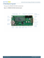
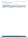
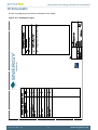
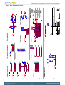
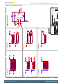
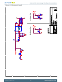
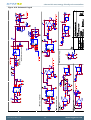
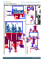
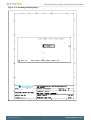
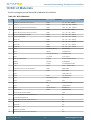
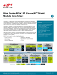
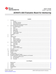
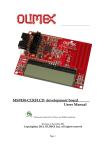
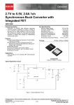
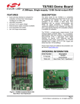
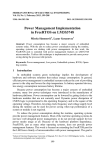
...the world's most energy friendly microcontrollers
USER MANUAL
Starter Kit EFM32TG-STK3300
Feature rich starter kit for evaluation, prototyping and application development for
the EFM32TG MCU family with the ARM Cortex-M3 CPU core.
Main features;
• Advanced Energy Monitoring provides real-time visibility into the energy
consumption of an application or prototype design.
• On-board debugger with debug out functionality
• 160-segment Energy Micro LCD
...the world's most energy friendly microcontrollers
1 Introduction
1.1 Features
•
•
•
•
•
•
•
•
•
•
•
Advanced Energy Monitoring system for precise current tracking.
Special hardware configuration for isolation of the MCU power domain.
Full feature USB debugger with debug out functionality.
160 segment Energy Micro LCD.
20 pin expansion header.
Breakout pads for easy access to I/O pins.
Powered by USB or CR2032 battery.
2 user buttons, 1 user LED and a touch slider.
Ambient Light sensor and inductive-capacitive metal sensor.
EFM32 Op-amp footprint.
32MHz and 32.768kHz crystal oscillators.
2011-05-13 - t0011_1.00
2
www.energymicro.com
...the world's most energy friendly microcontrollers
2 STK block diagram
An overview of the Kit is shown in the block diagram below.
Figure 2.1. EFM32TG-STK3300 Block Diagram
+ 3V
CR2032
Touch slider
4
Reset
28
1
3
2
4
Debug In/Out
EFM 3 2
2
1
Push buttons
Am bient
Light Sensor
20
LC sensor
LED
1
1
Opam p
Footprint
3
BC
USB m ini B
Breakout pads
EXP
2011-05-13 - t0011_1.00
3
www.energymicro.com
...the world's most energy friendly microcontrollers
3 Hardware layout
The layout of the EFM32TG-STK3300 is shown below.
Figure 3.1. EFM32TG-STK3300 hardware layout
2011-05-13 - t0011_1.00
4
www.energymicro.com
...the world's most energy friendly microcontrollers
4 Power supply
4.1 USB
The EFM32TG-STK3300 can get its power from the USB port. The MCU voltage will be 3.3 volts when
USB is connected.
4.2 Battery
There is a socket for a 20mm coin cell battery, which can be used to power the kit. When the battery
connect switch position is towards the battery, the EFM and its peripherals is powered by the battery.
The board controller/AEM is not powered by the battery, so the BSP software support library cannot be
used without USB connected. The current consumption while running on battery will be zero since the
battery supply is not part of the AEM.
Note
Make sure that the battery is inserted with the correct polarity.
2011-05-13 - t0011_1.00
5
www.energymicro.com
...the world's most energy friendly microcontrollers
5 Reset infrastructure
5.1 MCU
The primary user reset for the EFM32 MCU is the reset button on the board. This will only reset the
EFM32 MCU. The MCU can also be reset by the internal debugger or an external debugger.
5.2 Board controller
The board controller can only be reset by pulling and reinserting the USB cable. While on battery power
this will not reset the EFM32 MCU.
2011-05-13 - t0011_1.00
6
www.energymicro.com
...the world's most energy friendly microcontrollers
6 Peripherals
The starter kit has a set of peripherals that showcase some of the features of the EFM32TG.
Be aware that most EFM32 I/O routed to peripherals are also routed to the breakout pads. This must be
taken into consideration when using the breakout pads for your application.
6.1 Pushbuttons
The kit has two user pushbuttons marked PB0 and PB1. They are connected to the EFM32, and are
debounced by RC filters with a time constant of 1ms.
6.2 LED
There is one LED on the kit marked USER LED. An active high on the respective pin will light the LED.
6.3 LCD
A 28-pin Energy Micro LCD display is connected to the EFM32. The LCD has 8 common lines and 20
segment lines. This gives a total of 160 segments in 8-plexed mode. These lines are not shared on the
breakout pads. Capacitors for the EFM32TG LCD boost function is also available on the EFM32TGSTK3300.
6.4 Touch slider
A touch slider utilizing the capacitive touch capability is available. It is placed under the two push buttons
on the kit, above the "TOUCH SLIDER" print.
6.5 Ambient Light Sensor
The kit has a light sensitive, transistor type, ambient light sensor connected to the low energy sensor
interface of the EFM32TG MCU. The sensor is placed above the push buttons and can be used to sense
changes in ambient light levels.
6.6 LC Sensor
In the bottom right corner there is an inductive-capacitive sensor for demonstrating the low energy sensor
interface. By setting up oscillating currents in the inductor, metal nearby the inductor can be sensed by
measuring the oscillation decay time. The effective range is a few millimeters.
6.7 Op-Amp Footprint
If the kit is flipped over there is a silk-print model of a typical operational amplifier feedback circuit. The
actual operational amplifier is one of the op-amps inside the EFM32. By soldering 0603 sized resistors
the EFM32 internal operational amplifier can be evaluated with exact resistor values.
2011-05-13 - t0011_1.00
7
www.energymicro.com
...the world's most energy friendly microcontrollers
7 Advanced Energy Monitor
7.1 Usage
The AEM (Advanced Energy Monitor) data is collected by the board controller and can be displayed
by the energyAware Profiler, available through Simplicity Studio. By using the energyAware Profiler,
current consumption and voltage can be measured and linked to the actual code running on the EFM32
in realtime.
7.2 AEM theory of operation
In order to be able to measure currents ranging from 0.1uA to 50mA (114dB dynamic range), two current
sense amplifiers are utilized. The amplifiers measure voltage drop over a small series resistor and
translates this into a current. Each amplifier is adjusted for current measurement in a specific range.
The ranges for the amplifiers overlap and a change between the two occurs when the current is 200uA.
To reduce noise, averaging of the samples is performed before the current measurement is presented
in the AEM GUI.
During startup of the kit, an automatic calibration of the AEM is performed. This calibration compensates
for the offset error in the sense amplifiers.
7.3 AEM accuracy and performance
The Advanced Energy Monitor is capable of measuring currents in the range of 0.1uA to 50mA. For
currents above 200uA, the AEM is accurate within 0.1mA. When measuring currents below 200uA, the
accuracy increases to 1uA. Even though the absolute accuracy is 1uA in the sub 200uA range, the AEM
is able to detect changes in the current consumption as small as 100nA The measurement bandwidth
of the AEM is 60Hz when measuring currents below 200uA and 120Hz when measuring currents above
200uA. The table below summarizes the accuracy of the two current sense amplifiers in different ranges.
Table 7.1. AEM accuracy
Current range
Low gain amplifier accuracy
High gain amplifier accuracy
50mA
0.1mA
-
1mA
0.1mA
-
200uA
0.01mA
1uA
10uA
-
0.1uA
1uA
-
0.1uA
Note
The current measurement will only be correct when powering the EFM32 from USB power.
The battery switch should be in the position furthest away from the battery.
2011-05-13 - t0011_1.00
8
www.energymicro.com
...the world's most energy friendly microcontrollers
8 Board controller
The control MCU can act as a board controller (BC). There is a UART connection between the EFM32
and the BC. The connection is made by setting the bc_en line high. The EFM32 can then use the BSP
(Board Support Package) library functions to send commands to the BC. When bc_en is low, bc_tx and
bc_rx can be used by other applications.
To use the board controller for your application, the Board Support Package must be installed. See the
BSP chapter to find out how.
Note
The board controller is only available when USB power is connected.
2011-05-13 - t0011_1.00
9
www.energymicro.com
...the world's most energy friendly microcontrollers
9 Board Support Package
The Board Support Package (BSP) is a set of C source and header files that enables easy access to,
and control over some board specific features.
Compared to the Energy Micro development kit, the functionality is limited. Unless you need/want some
of the functions contained in the BSP, there is really no need to include or use it. The EFM32 in the Starter
Kit is fully usable without BSP support, and you can use all peripherals in the efm32lib without the BSP.
The BSP use EFM32 peripheral USART1 (TX pin PD7, RX pin PD6) on baudrate 115200-8-N-1 to
communicate with the board controller.
Note
The BSP is only functional when the Starter Kit is USB-powered, using these function calls
with USB disconnected will give unpredictable results.
9.1 Installation location
When installing Simplicity Studio, the BSP will be installed in the user directory, typically in a location
such as
Win7: C:\Users\[username]\AppData\Roaming\energymicro\boards
or something similar (depending on your OS/Windows version). All files in the board support package
is prefixed by stk.
9.2 Application Programming Interface
To use the BSP, include the Starter Kit header file, like this:
#include "stk.h"
All functions in the BSP are prefixed with STK_. The main initialization routine is defined as
void STK_Init(void);
and must be called before any access to the STK-functions. This function call will setup the UART
communication channel with a 115800 baud rate. This baud rate depends on the current core clock, so
correct clock configuration should be set before calling this function.
bool STK_Ready(void);
Returns true if the board controller is responding. A non-responding board will either return false, or
hang (i.e. if the EFM32 is powered by the CR2032 battery cell).
float STK_Current(void);
Returns instant current usage in milliamperes.
float STK_Voltage(void);
2011-05-13 - t0011_1.00
10
www.energymicro.com
...the world's most energy friendly microcontrollers
Returns instant voltage (VMCU) reading in volt.
bool STK_EnergyMode(uint8_t em);
Informs the board controller about the Energy Mode (sleep mode) we are going into. This information
can be used by the board controller to present a richer visual graph for illustrating what the EFM32 is
currently doing.
In addition to these main functions, full documentation of the complete API is included in the Doxygen/
HTML documentation of the installed package.
9.3 Example Applications
Under the EFM32_Gxxx_STK/examples folder in your installation directory, you will find an example
program using the BSP, with corresponding project/Makefiles for the supported IDEs.
9.4 How to include in your own applications
The easiest way to include the BSP in your application is to base your work on the example application
that use the BSP. The following items are recommended for correct configuration:
1. Make sure you define the correct part number (i.e. EFM32TG840F32) as a preprocessor defined
symbol
2. Make sure you define the correct part number (i.e. EFM32TG840F32) for your project file
3. Add and include the EFM32_CMSIS-files (startup_efm32.s, system_efm32.c, core_cm3.c) to your
project
4. Add and include _all_ BSP package .c-files, with the stk-prefix to your project
5. Configure include paths to point at the CMSIS/CM3/CoreSupport and CMSIS/CM3/DeviceSupport/
EnergyMicro/EFM32 directories
6. Configure include paths to point to the EFM32_Gxxx_STK/bsp directory
Make sure you call "STK_Init()" early at startup, and you should be all set.
2011-05-13 - t0011_1.00
11
www.energymicro.com
...the world's most energy friendly microcontrollers
10 Connectors
10.1 Breakout pads
Most I/O except the LCD pins are routed to the breakout pads at the top and bottom edge of the kit. A
2.54mm (100 mil) pitch pin header can be soldered in place on the pads for easier access.
Some of the breakout pads are not connected and therefore marked NC. The position of the connected
pins are compatible with the EFM32G Gecko starter kit.
Note
Some of the breakout pads are shared by on-board EFM peripherals. The schematic must
be consulted to make sure that it is OK to use a shared pin in your application.
Figure 10.1. Breakout pads and layout diagram
3
3V
U
C
VM C
N
C
N
8
PD7
PD 6
PD D
N
G 5
PD4
PD 3
PD 2
PD 1
PD0
PD D
N
G 1
PD 2
1
PB1 1
PB D
N
G 4
PD
C
N
5V
Debug header in/out
1
20
EXP
header
Am bient Light
Sensor
USB
+ 3V
CR2032
V+
VMCU
GND
SWO
Reset
User LED
EFM 3 2 TG8 4 0
QFN 6 4
PB0
PB1
J100
PC13
PC12
PC7
PC5
PC6
LC
Sensor
AEM Connector
Touch Slider
12
O
SWC
SWD
SW ST
R
# D
N
G
3
3 VCU
VM 4
1
PCC
N
D
N
G
C
N
6
PC 2
PD4
PC
C
N
C
N
C
N
8
PD D
N
G
C
N
C
N
C
N
C
N
D
N
G
14
PA 3
1
PA1 2
PA
5V
2011-05-13 - t0011_1.00
www.energymicro.com
...the world's most energy friendly microcontrollers
10.2 Expansion header
A 20 pin expansion header can be used to connect plugin boards. This contains a selection of I/O,
powers and ground. See the pinout in the table below.
Table 10.1. Expansion header pinout
I/O
#
#
I/O
GND
1
2
VMCU
PC4
3
4
PD0
PC5
5
6
PD1
PC12
7
8
PD2
PC13
9
10
PD3
PB11
11
12
PD4
PB12
13
14
PD5
PD7
15
16
PD6
PD8
17
18
5V
GND
19
20
3V3
2011-05-13 - t0011_1.00
13
www.energymicro.com
...the world's most energy friendly microcontrollers
Table 10.2. Expansion header pin list
EXP header pin
number
MCU GPIO pin
Some MCU GPIO pin functions
1
GND
Ground
2
VMCU
MCU supply voltage
3
PC4
OPAMP_P0 #0 / LETIMER_OUT0 #3 / ACMP0_CH4 / LES_CH4
4
PD0
ADC0_CH0 / USART1_TX #1 / OPAMP_OUT2 #1
5
PC5
OPAMP_N0 #0 / LETIMER_OUT1 #3 / ACMP0_CH5 / LES_CH5 #0
6
PD1
ADC0_CH1 / TIMER0_CC0 #3 / USART1_RX #1 / OPAMP_OUT1ALT #4
7
PC12
CMU_CLKOUT0 #1 / ACMP1_CH4 / LES_CH12 #0
8
PD2
ADC0_CH2 / TIMER0_CC1 #3 / USART1_CLK #1
9
PC13
ACMP1_CH5 #0 / TIM1_CC0 #0 / TIM1_CC2 #4 / PCNT0_S0IN #0 / LES_CH13
#0
10
PD3
ADC0_CH3 / OPAMP_N2 #0 / TIM0_CC2 #3 / US1_CS #1
11
PB11
DAC0_OUT0 #0 / OPAMP_OUT0 #0 / TIM1_CC2 #3 / LETIM0_OUT0 #1
12
PD4
ADC0_CH4 / OPAMP_P2 #0 / LEU0_TX #0
13
PB12
DAC0_OUT1 #0 / OPAMP_OUT1 #0 / LETIM0_OUT1 #1
14
PD5
ADC0_CH5 / OPAMP_OUT2 #0 / LEU0_RX #0
15
PD7
ADC0_CH7 / OPAMP_N1 #0 / TIM1_CC1 #4 / I2C0_SCL #1 / LES_ALTEX1 #0 /
ACMP1_O #2
16
PD6
ADC0_CH6 / OPAMP_P1 #0 / TIM1_CC0 #4 / I2C0_SDA #1 / LES_ALTEX0 #0 /
ACMP0_O #2
17
PD8
CMU_CLKOUT1 #1
18
5V
USB Power
19
GND
Ground
20
3V3
3.3V board power
10.3 Debug connector
This connector is used for Debug In and Debug Out (see Debug chapter). The pinout is described in
the table.
2011-05-13 - t0011_1.00
14
www.energymicro.com
...the world's most energy friendly microcontrollers
Table 10.3. Debug connector pinout
Pin
number
Function
Note
1
VTARGET
Target voltage on the debugged application.
2
NC
3
/TRST
4
GND
5
TDI
6
GND
7
TMS/SWDIO
8
GND
9
TCK
10
GND
11
RTCK
12
GND
13
TDO/SWO
14
GND
15
/RESET
16
GND
17
PD
This pin has a 100k pulldown.
18
Cable detect
This signal must be pulled to ground by the external debugger or application for cable
insertion detection.
19
PD
This pin has a 100k pulldown.
20
GND
2011-05-13 - t0011_1.00
JTAG tap reset
JTAG data in
JTAG TMS or Serial Wire data I/O
JTAG TCK or Serial Wire clock
JTAG RTCK
JTAG TDO or Serial Wire Output
Target MCU reset
15
www.energymicro.com
...the world's most energy friendly microcontrollers
11 Debugging
The EFM32TG-STK3300 has an on-board debugger, and it can be used in different ways to debug the
EFM32, both on and off kit. Below are descriptions on the different modes. Check the configuration
chapter to find out how to change the debug setting.
Table 11.1. Debug modes
Mode
Description
Debug MCU
In this mode the on-board debugger is connected to EFM32 on the EFM32TG-STK3300.
Debug IN
In this mode the on-board debugger is disconnected, and an external debugger can be connected to
debug the EFM32 on the EFM32TG-STK3300.
Debug OUT
In this mode the on-board debugger can be used to debug an EFM32 mounted in your own
application.
11.1 Debugging during battery operation
When the EFM32 is powered by the battery and the USB is still connected, the on-board debug
functionality is available. If the USB power is disconnected the debug controller on the kit will not work.
To enable debugging in this mode, connect an external debugger (e.g. another EFM32TG-STK3300)
to the debug pads in the bottom right corner of the EFM32TG-STK3300. These pads are connected
directly to the EFM32 debug interface.
2011-05-13 - t0011_1.00
16
www.energymicro.com
...the world's most energy friendly microcontrollers
12 Integrated Development Environments
The Energy Micro software packages contains various examples in source form to use with the Starter
Kit. The following IDEs are supported.
12.1 IAR Embedded Workbench for ARM
An evaluation version of IAR Embedded Workbench for ARM is included on a CD in the EFM32TGSTK3300 package. Check the quick start guide for where to find updates, and IAR's own documentation
on how to use it. You will find the IAR project file in the
iar
subfolder of each project
12.2 Rowley Associates - CrossWorks for ARM
See the quick start guide for download details for CrossWorks for ARM. You will find CrossWorks project
files in the
rowley
subfolder of each project.
12.3 CodeSourcery - Sourcery G++
See the quick start guide for download details for Sourcery G++. The
codesourcery
subfolder contains Makefiles for use with the Sourcery G++ development environment.
12.4 Keil - MDK-ARM
See the quick start guide for download details for evaluation versions of Keil MDK-ARM. The
arm
subfolder in each project contains project files for MDK-ARM. Please see the MDK-ARM documentation
for usage details.
2011-05-13 - t0011_1.00
17
www.energymicro.com
...the world's most energy friendly microcontrollers
13 energyAware Commander and Upgrades
The energyAware Commander is a program that comes with Simplicity Studio. It can perform various
kit and EFM32 specific tasks.
13.1 eA Commander Operation
This utility gives the ability to program the EFM32, upgrade the kit, lock and unlock devices and more.
Some of the features will only work with Energy Micro kits, while other will work with a J-Link debugger
connected. Press the "F1" button, or select the "Help->Help" menu item for a full description.
13.2 Upgrades
Upgrading the kit is done through Simplicity Studio. The Studio will automatically check for new updates
on startup.
You can also use the energyAware Commander for manual upgrades. Select the "Kit" icon, use the
"Browse" button to select the correct file ending in ".emz", and press the "Install package button".
2011-05-13 - t0011_1.00
18
www.energymicro.com
...the world's most energy friendly microcontrollers
14 Errata
The following sections lists the erratas and known issues for operating the STK. You can read the STK
revision on the white label on the back side of the STK. It is in the format "BRD2100, Rev: Axx".
14.1 Chip errata
You can use energyAware Commander and press the "Connect" button to retrieve EFM32 revision
information. Download the chip errata from http://www.energymicro.com for the latest errata updates
on your device.
14.2 efm32lib Chip Init routine
The efm32lib
#include "efm32_chip.h"
CHIP_Init()
routine will, as far as possible, enable work arounds for chip erratas to make EFM32 Tiny Gecko devices
be as software compatible as possible. In some cases, this can introduce increased current. See the
device errata and source code for details.
14.3 STK Revision Errata
Table 14.1. BRD2100 Revision Errata
Revision Problem
Description
.
.
.
2011-05-13 - t0011_1.00
19
www.energymicro.com
...the world's most energy friendly microcontrollers
15 Version information
The current version information can be read from Gecko Commander.
Table 15.1. Current versions
Type
Version
Released
Firmware revision
1.5.0
13.05.2011
Board
BRD2100A Rev. A03
13.05.2011
2011-05-13 - t0011_1.00
20
www.energymicro.com
...the world's most energy friendly microcontrollers
16 Schematic
On the next pages you can find the schematic of the board.
Figure 16.1. Schematic Page 1
2011-05-13 - t0011_1.00
21
www.energymicro.com
...the world's most energy friendly microcontrollers
Figure 16.2. Schematic Page 2
2011-05-13 - t0011_1.00
22
www.energymicro.com
...the world's most energy friendly microcontrollers
Figure 16.3. Schematic Page 3
2011-05-13 - t0011_1.00
23
www.energymicro.com
...the world's most energy friendly microcontrollers
Figure 16.4. Schematic Page 4
2011-05-13 - t0011_1.00
24
www.energymicro.com
...the world's most energy friendly microcontrollers
Figure 16.5. Schematic Page 5
2011-05-13 - t0011_1.00
25
www.energymicro.com
...the world's most energy friendly microcontrollers
Figure 16.6. Schematic Page 6
2011-05-13 - t0011_1.00
26
www.energymicro.com
...the world's most energy friendly microcontrollers
Figure 16.7. Schematic Page 7
2011-05-13 - t0011_1.00
27
www.energymicro.com
...the world's most energy friendly microcontrollers
Figure 16.8. Schematic Page 8
2011-05-13 - t0011_1.00
28
www.energymicro.com
...the world's most energy friendly microcontrollers
Figure 16.9. Schematic Page 9
2011-05-13 - t0011_1.00
29
www.energymicro.com
...the world's most energy friendly microcontrollers
Figure 16.10. Schematic Page 10
2011-05-13 - t0011_1.00
30
www.energymicro.com
...the world's most energy friendly microcontrollers
17 Assembly Drawing
On the next pages you can find the assembly drawings of the board (not to scale).
Figure 17.1. Assembly Drawing Page 1
2011-05-13 - t0011_1.00
31
www.energymicro.com
...the world's most energy friendly microcontrollers
Figure 17.2. Assembly Drawing Page 2
2011-05-13 - t0011_1.00
32
www.energymicro.com
...the world's most energy friendly microcontrollers
18 Bill of Materials
On the next pages you can find the Bill of Materials for the board.
Table 18.1. Bill of Materials
Qty.
Reference
Manufacturer
Manufacturers Part Number
7
C100,C101,C708,C709,C712,C713,C718
Murata
1N
1
C198
Murata
330P
50V
C0G
GRM155
39
C199,C401,C402,C403,C404,C408,C600,C603,...
Murata
100N
16V
X7R
GRM155
3
C400,C501,C716
Murata
1U
12
C407,C409,C601,C700,C703,C714,C719,C720,...
Murata
10U
10V
X5R
GRM21
6
C410,C411,C890,C905,C908,C909
Murata
10N
16V
X7R
GRM155
4
C412,C413,C902,C903
Murata
12P
50V
C0G
GCM155
2
C414,C415
Murata
22P
50V
C0G
GCM155
1
C500
Murata
22N
16V
X7R
GRM155
2
C602,C705
Murata
33N
16V
X7R
GRM155
2
C900,C901
Murata
18P
50V
C0G
GCM155
1
D600
NXP Semiconductors
IP4220CZ6,125
1
D703
National
LM4040CIM3-3.0
1
D800
Vishay Semiconductors
VESD05A8A-HNH
1
LCD1
Tri-T Co Ltd
CL010-1087-03
3
LED100,LED900,LED902
Everlight
EL-19-21UYC/S530-A2/TR8
1
LED901
Panasonic
LNJ926W8CRA
1
LED903
Everlight
19-21SDRC/S530-A3/TR8
1
L100
Bourns
390UH
9
L400,L660,L700,L701,L730,L780,L800,L801,...
Murata
BLM21B102S
1
L600
Murata
BLM41P600S
1
PCB1
1
P100
Taitek
HE2-20G6C394-5R
1
P601
Hirose Electric Co Ltd
UX60-MB-5ST
1
P700
Keystone
3002
1
P800
3M
D2520-6V0C-AR-WE
1
Q100
Vishay
TEMT6200FX01A
1
Q702
ON Semiconductor
BC846BWT1G
2
RP800,RP801
ROHM
MNR04M0APJ330
6
R100,R103,R401,R730,R750,R810
100R
11
R101,R102,R680,R681,R682,R686,R687,R708,...
1M
5
R190,R900,R903,R905,R912
2K
15
R195,R197,R198,R704,R719,R721,R771,R773,...
0R
2
R196,R901
1K5
2
R199,R706
22K
2
R241,R242
0R
4
R400,R717,R724,R910
1R
10
R600,R609,R612,R700,R713,R714,R715,R716,...
10K
2011-05-13 - t0011_1.00
16V
X7R
10V
X5R
GRM155
GRM18
SDR0302-391KL
PCB2100 Rev. A03
33
www.energymicro.com
...the world's most energy friendly microcontrollers
Qty.
Reference
2
R601,R702
180K
2
R602,R703
110K
9
R603,R604,R605,R606,R729,R802,R803,R804,...
100K
6
R607,R608,R660,R774,R807,R808
4K7
2
R610,R814
10M
1
R611
180K
1
R701
3
R705,R728,R772
1K
3
R707,R727,R801
47K
1
R709
1K8
0.1%
1
R710
43R
0.1%
1
R711
4R7
0.1%
1
R712
0R
1
R718
12K
0.1%
1
R720
10K
0.1%
1
R760
10M
1%
3
R781,R805,R806
33R
2
R902,R904
22R
3
SW100,SW101,SW400
Omron Electronics
B3S1000
1
SW700
C&K Components
JS202011SCQN
2
U600,U701
National Semiconductor
LP3982ILDX-ADJ
1
U601
Microchip
24AA024-I/MS
4
U602,U695,U702,U805
Texas Instruments
TS3A4751RUCR
3
U660,U803,U804
NXP
74LVC2G125DC
1
U700
Texas Instruments
TS5A3159ADBVR
2
U703,U705
National Semiconductor
LTC6102CDD#PBF
1
U704
Texas Instruments
TLV272CDGK
3
U706,U707,U850
Microchip Technology
MCP6001T-I/OT
3
U800,U802,U806
NXP
74LVC4066BQ
1
U801
Texas Instruments
74LVC16T245DGG
1
U902
Numonyx
M25PX16-VMP6E
1
U904
Energy Micro
EFM32TG840
1
X400
NDK
NX5032GA-32.000M
1
X401
Golledge
GSWX-26
1
X900
NDK
NX5032GA-16.000000MHZ
2011-05-13 - t0011_1.00
Manufacturer
Bourns
34
Manufacturers Part Number
4R7
0.1%
CRT1206-BY-4R7-ELFTR
0.1%
www.energymicro.com
...the world's most energy friendly microcontrollers
19 Document Revision History
19.1 Revision 1.00
2011-05-13
Initial revision.
2011-05-13 - t0011_1.00
35
www.energymicro.com
...the world's most energy friendly microcontrollers
A Disclaimer and Trademarks
A.1 Disclaimer
Energy Micro AS intends to provide customers with the latest, accurate, and in-depth documentation
of all peripherals and modules available for system and software implementers using or intending to
use the Energy Micro products. Characterization data, available modules and peripherals, memory
sizes and memory addresses refer to each specific device, and "Typical" parameters provided can and
do vary in different applications. Application examples described herein are for illustrative purposes
only. Energy Micro reserves the right to make changes without further notice and limitation to product
information, specifications, and descriptions herein, and does not give warranties as to the accuracy
or completeness of the included information. Energy Micro shall have no liability for the consequences
of use of the information supplied herein. This document does not imply or express copyright licenses
granted hereunder to design or fabricate any integrated circuits. The products must not be used within
any Life Support System without the specific written consent of Energy Micro. A "Life Support System"
is any product or system intended to support or sustain life and/or health, which, if it fails, can be
reasonably expected to result in significant personal injury or death. Energy Micro products are generally
not intended for military applications. Energy Micro products shall under no circumstances be used in
weapons of mass destruction including (but not limited to) nuclear, biological or chemical weapons, or
missiles capable of delivering such weapons.
A.2 Trademark Information
Energy Micro, EFM32, EFR, logo and combinations thereof, and others are the registered trademarks or
trademarks of Energy Micro AS. ARM, CORTEX, THUMB are the registered trademarks of ARM Limited.
Other terms and product names may be trademarks of others.
2011-05-13 - t0011_1.00
36
www.energymicro.com
...the world's most energy friendly microcontrollers
B Contact Information
B.1 Energy Micro Corporate Headquarters
Postal Address
Visitor Address
Technical Support
Energy Micro AS
P.O. Box 4633 Nydalen
N-0405 Oslo
NORWAY
Energy Micro AS
Sandakerveien 118
N-0484 Oslo
NORWAY
support.energymicro.com
Phone: +47 40 10 03 01
www.energymicro.com
Phone: +47 23 00 98 00
Fax: + 47 23 00 98 01
B.2 Global Contacts
Visit www.energymicro.com for information on global distributors and representatives or contact
[email protected] for additional information.
Americas
Europe, Middle East and Africa Asia and Pacific
www.energymicro.com/americas www.energymicro.com/emea
2011-05-13 - t0011_1.00
37
www.energymicro.com/asia
www.energymicro.com
...the world's most energy friendly microcontrollers
Table of Contents
1. Introduction .............................................................................................................................................. 2
1.1. Features ....................................................................................................................................... 2
2. STK block diagram .................................................................................................................................... 3
3. Hardware layout ........................................................................................................................................ 4
4. Power supply ........................................................................................................................................... 5
4.1. USB ............................................................................................................................................. 5
4.2. Battery .......................................................................................................................................... 5
5. Reset infrastructure ................................................................................................................................... 6
5.1. MCU ............................................................................................................................................ 6
5.2. Board controller .............................................................................................................................. 6
6. Peripherals ............................................................................................................................................... 7
6.1. Pushbuttons ................................................................................................................................... 7
6.2. LED ............................................................................................................................................. 7
6.3. LCD ............................................................................................................................................. 7
6.4. Touch slider ................................................................................................................................... 7
6.5. Ambient Light Sensor ...................................................................................................................... 7
6.6. LC Sensor ..................................................................................................................................... 7
6.7. Op-Amp Footprint ........................................................................................................................... 7
7. Advanced Energy Monitor ........................................................................................................................... 8
7.1. Usage ........................................................................................................................................... 8
7.2. AEM theory of operation .................................................................................................................. 8
7.3. AEM accuracy and performance ........................................................................................................ 8
8. Board controller ........................................................................................................................................ 9
9. Board Support Package ............................................................................................................................ 10
9.1. Installation location ........................................................................................................................ 10
9.2. Application Programming Interface ................................................................................................... 10
9.3. Example Applications ..................................................................................................................... 11
9.4. How to include in your own applications ............................................................................................ 11
10. Connectors ........................................................................................................................................... 12
10.1. Breakout pads ............................................................................................................................ 12
10.2. Expansion header ........................................................................................................................ 13
10.3. Debug connector ......................................................................................................................... 14
11. Debugging ............................................................................................................................................ 16
11.1. Debugging during battery operation ................................................................................................ 16
12. Integrated Development Environments ....................................................................................................... 17
12.1. IAR Embedded Workbench for ARM ............................................................................................... 17
12.2. Rowley Associates - CrossWorks for ARM ....................................................................................... 17
12.3. CodeSourcery - Sourcery G++ ....................................................................................................... 17
12.4. Keil - MDK-ARM ......................................................................................................................... 17
13. energyAware Commander and Upgrades ................................................................................................... 18
13.1. eA Commander Operation ............................................................................................................. 18
13.2. Upgrades ................................................................................................................................... 18
14. Errata .................................................................................................................................................. 19
14.1. Chip errata ................................................................................................................................. 19
14.2. efm32lib Chip Init routine .............................................................................................................. 19
14.3. STK Revision Errata .................................................................................................................... 19
15. Version information ................................................................................................................................ 20
16. Schematic ............................................................................................................................................ 21
17. Assembly Drawing ................................................................................................................................. 31
18. Bill of Materials ..................................................................................................................................... 33
19. Document Revision History ...................................................................................................................... 35
19.1. Revision 1.00 .............................................................................................................................. 35
A. Disclaimer and Trademarks ....................................................................................................................... 36
A.1. Disclaimer ................................................................................................................................... 36
A.2. Trademark Information ................................................................................................................... 36
B. Contact Information ................................................................................................................................. 37
B.1. Energy Micro Corporate Headquarters .............................................................................................. 37
B.2. Global Contacts ............................................................................................................................ 37
2011-05-13 - t0011_1.00
38
www.energymicro.com
...the world's most energy friendly microcontrollers
List of Figures
2.1. EFM32TG-STK3300 Block Diagram ........................................................................................................... 3
3.1. EFM32TG-STK3300 hardware layout .......................................................................................................... 4
10.1. Breakout pads and layout diagram ......................................................................................................... 12
16.1. Schematic Page 1 ............................................................................................................................... 21
16.2. Schematic Page 2 ............................................................................................................................... 22
16.3. Schematic Page 3 ............................................................................................................................... 23
16.4. Schematic Page 4 ............................................................................................................................... 24
16.5. Schematic Page 5 ............................................................................................................................... 25
16.6. Schematic Page 6 ............................................................................................................................... 26
16.7. Schematic Page 7 ............................................................................................................................... 27
16.8. Schematic Page 8 ............................................................................................................................... 28
16.9. Schematic Page 9 ............................................................................................................................... 29
16.10. Schematic Page 10 ............................................................................................................................ 30
17.1. Assembly Drawing Page 1 .................................................................................................................... 31
17.2. Assembly Drawing Page 2 .................................................................................................................... 32
2011-05-13 - t0011_1.00
39
www.energymicro.com
...the world's most energy friendly microcontrollers
List of Tables
7.1. AEM accuracy ........................................................................................................................................ 8
10.1. Expansion header pinout ...................................................................................................................... 13
10.2. Expansion header pin list ...................................................................................................................... 14
10.3. Debug connector pinout ........................................................................................................................ 15
11.1. Debug modes ..................................................................................................................................... 16
14.1. BRD2100 Revision Errata ..................................................................................................................... 19
15.1. Current versions .................................................................................................................................. 20
18.1. Bill of Materials ................................................................................................................................... 33
2011-05-13 - t0011_1.00
40
www.energymicro.com