1
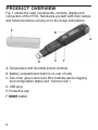
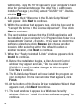
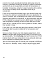
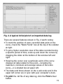
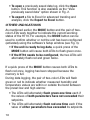
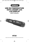
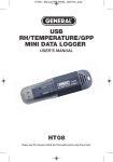
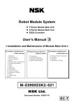
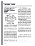
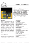
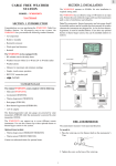
99 Washington Street
Melrose, MA 02176
Phone 781-665-1400
Toll Free 1-800-517-8431
Visit us at www.TestEquipmentDepot.com
USB RH/TEMPERATURE
DATA LOGGER
USER’S MANUAL
HT10
Please read this manual carefully and thoroughly before using this product.
TABLE OF CONTENTS
Introduction . . . . . . . . . . . . . . . . . . . . . . . . . . . . . . . . . . 3 – 4
Key Features . . . . . . . . . . . . . . . . . . . . . . . . . . . . . . . . . 4 – 5
Safety Instruction . . . . . . . . . . . . . . . . . . . . . . . . . . . . . . . . . 5
What’s in the Blister Pack. . . . . . . . . . . . . . . . . . . . . . . . . . . 5
Product Overview. . . . . . . . . . . . . . . . . . . . . . . . . . . . . . . . . 6
Setup Instructions . . . . . . . . . . . . . . . . . . . . . . . . . . . . 7 – 12
Installing/Replacing the Battery . . . . . . . . . . . . . . . . . 7
Install Software and Drivers . . . . . . . . . . . . . . . . . 7 – 9
Configure the Unit . . . . . . . . . . . . . . . . . . . . . . . 9 – 12
Operating Instructions . . . . . . . . . . . . . . . . . . . . . . . . 13 – 16
Deploy the Unit . . . . . . . . . . . . . . . . . . . . . . . . 13 – 14
Stop Logging and Import Logs . . . . . . . . . . . . . . . . . 14
Viewing, Printing and Exporting Data Logs . . . . 14 – 16
Other Indications . . . . . . . . . . . . . . . . . . . . . . . . . . . 16
Specifications . . . . . . . . . . . . . . . . . . . . . . . . . . . . . . . . . . 17
Maintenance Tips. . . . . . . . . . . . . . . . . . . . . . . . . . . . . . . . 18
Warranty Information . . . . . . . . . . . . . . . . . . . . . . . . . . . . . 18
Return for Repair Policy . . . . . . . . . . . . . . . . . . . . . . . . . . . 19
2
INTRODUCTION
Thank you for purchasing General Tools & Instruments’
HT10 USB RH/Temperature Data Logger. Please read this
user’s manual carefully and thoroughly before using the
instrument.
The HT10 is a low-cost, compact, battery-powered thermohygrometer capable of unattended logging (recording) of the
ambient temperature and relative humidity (RH) of an
environment for days, weeks or months. Data logging can
be started or stopped by pushing a button on the unit,
eliminating the need to bring a laptop to the job site.
After a data log has been captured and stored, it can be
uploaded as a .txt file to any PC running the Windows®7 or
Windows® XP operating system after plugging the HT10 into
one of the computer’s USB ports. The HT10’s internal flash
memory is large enough to store up to 8000 pairs of humidity
and temperature readings.
Included with the product—which is slightly larger than a
thumb drive—is a mini-disc with the drivers needed to
interface the unit to the computer, as well as software that
can display a data log file as a table or graph and/or export it
to Microsoft Excel. Exporting to Excel is recommended for
sophisticated trending and analysis of humidity and
temperature data and easy detection of unexpected
excursions.
Windows® 7 and Windows® XP are registered trademarks of Microsoft Corporation.
3
Applications for the HT10 include:
• Water damage restoration—Because the HT10 is
designed to be deployed and left in place over the
duration of the job, it is always in equilibrium with the
environment.
• Process control—The HT10 enables, simplifies and cuts
the cost of environmental monitoring of office buildings,
greenhouses, food and equipment storage facilities,
wineries, freezers, shipping containers, HVAC/R
installations, computer rooms, labs, libraries, museums
and saunas.
• Electronics manufacturing—Alerts provided by the lowhumidity alarm function of the HT10 can mitigate the risk
of damaging high-voltage static discharges.
KEY FEATURES
• One button starts/stops data logging without a PC
• Plug-and-play USB 2.0 interface; no need for cables,
cradles or docks
• Large storage capacity: Up to 8000 pairs of humidity and
temperature readings
• Two LEDs indicate device working status and
“memory full”
• Included software is used to set: Sampling time from
10 seconds to 12 hours; Hi/Lo alarm setpoints for
humidity and temperature; Temperature unit (°F or °C)
• Software also calculates dew point and displays data logs
as time-based graphs synchronized to your PC’s clock
4
• One-click exporting of logs to Excel or Word
• Long battery life (up to one year)
• Includes USB extension cable
• One-year warranty
SAFETY INSTRUCTION
Do not use the HT10 in the presence of flammable or
explosive gases.
WHAT’S IN THE BLISTER PACK
The HT10 comes in a blister pack that also contains
• One “1/2 AA” battery
• A disc with software drivers for Windows7 or Windows
XP computers, a program for capturing data logs and
displaying them as curves, and a PDF of this user’s
manual
• A USB extension cable
• A hard copy of this user’s manual (inside the fold-over
card)
5
PRODUCT OVERVIEW
Fig. 1 shows the main components, controls, display and
connectors of the HT10. Familiarize yourself with their names
and functions before moving on to the Setup Instructions.
E
B
A
D
C
F
A. Temperature and humidity sensor window
B. Battery compartment (latch is on rear of unit)
C. Two-color (green and red) LEDs (indicate device logging
and configuration status and “memory full”)
D. USB plug
E. Protective cap
F. MODE button
6
SETUP INSTRUCTIONS
INSTALLING/REPLACING THE BATTERY
LATCH
The HT10 uses a 3.6VDC “1/2 AA” Lithium-ion battery.
To open the battery compartment, use a paper clip or a
screwdriver with a fine point to push in the silver flange
showing through the small square hole in the rear of the unit
(left photo above). Push back the cover (middle photo),
remove the old battery (right photo) and insert a fresh battery
in the correct orientation. Then replace the cover, pushing it
forward until you feel and hear a click.
Whenever you change the battery, each of the two LEDs will
flash red once, and then green once.
Note: If the battery is removed from a unit before it has been
set up from software or while it is recording, the unit must be
reconfigured before it can be reactivated. If it is not
reconfigured, the unit will remain in standby mode.
INSTALL SOFTWARE AND DRIVERS
1. Place mini-disc in tray of CD/DVD drive, shiny side down.
Close tray.
2. When the AutoPlay window appears, click on “Open folder
to view files using Windows Explorer.”
3. Windows Explorer will indicate that there are two “Files
Currently on the Disc”. One is actually a folder containing
a PDF of the HT10 user’s manual (as well as PDFs of the
manuals for the HT20 and HT50—versions of the HT10
7
with LCDs). Copy the HT10 manual to your computer’s hard
drive for permanent storage. The other file is a Windows
Installer Package (.msi file) named “ELUSB V1.0”. Doubleclick its icon.
4. A window titled “Welcome to the ELUsb Setup Wizard”
will appear. Click Next to continue.
5. Within the window that appears next, click the box next to
“I accept the terms in the License Agreement”. Then click
Next to continue.
6. The next window advises that the ELUSB application will
be installed in your computer’s C:\Program Files folder in a
new subfolder named <ELUSB>. If you want to install the
software elsewhere, click Browse and choose another
location. After selecting either the default location or
another location, click Next to continue.
7. When the “Ready to install ELUsb” window appears, click
Install to continue.
8. Before the installation begins, a User Account Control
window may appear and ask, “Do you want to allow
[ELUSB V1.0.msi] to make changes to this computer?”
Click Yes to continue.
9. The ELUsb Setup Wizard will now install the program on
your computer. On the next window that appears, click
Finish.
10. At the bottom of the Device Driver Installation Wizard that
appears next, click Next to continue.
11. The next window to appear is a Windows Security
window. Click on “Install this driver software anyway” to
continue.
8
12. The next Device Driver Installation Wizard window will
advise you that an HT10/20/50 driver from General Tools
or Kecheng Laboratories was successfully installed and
that your device is now “Ready to use.” Click Finish to
continue.
CONFIGURE THE UNIT
Note that the software installation has added a icon to
your desktop. To facilitate access to the program, right-click
on the icon and pin it to both your Start button and the Quick
Start area at the left of your taskbar. You can now eject the
installation mini-disc and store it with your other important
software.
Plug the HT10 into an available USB port of your computer. If
your computer is a laptop and the only available USB jack
does not have enough vertical clearance to accommodate
the HT10 without mechanically stressing its USB plug, do
not plug the HT10 directly into the jack. You do not want
the plug of the HT10 to support any of the weight of the
laptop. If that is the case, plug the HT10 into the jack of the
included USB extension cable and insert the plug of the
extension cable into the computer’s USB jack.
The first time you plug the HT10 into your computer, your
system tray will notify you that the computer is “Installing
Device Driver Software”. When the notification disappears,
open the ELUSB program by selecting it via your Start button,
clicking on its icon on your taskbar, or double-clicking its
desktop icon.
If the software has installed correctly and you have plugged
the HT10 into a working USB port of your computer, the
following screen should appear on your computer’s display.
9
Device HT10 is connected!
Fig. 2. The three options made available by
plugging the HT10 into a USB port
Note: If you have already used your HT10 to log data
and it is still in recording mode, plugging the unit in
will cause the following window to appear.
Click Yes to stop recording and import all data recorded to
that point in time. Click No to continue to Setup without
importing recorded data (meaning it will be lost). Click
Cancel to go back and unplug the unit from the USB port.
10
You can now use the software to “configure” your HT10.
Configuring the device means choosing four key parameters:
• Sampling time—How often it makes and stores
humidity and temperature measurements.
• Temperature unit—degrees Fahrenheit or Celsius
(°F or °C).
• High and low temperature alarm setpoints
• High and low humidity alarm setpoints
To begin, click on “Set up the USB Data Logger” in the
window shown in the figure above. Doing so will cause the
following window to appear.
Device HT10 is connected!
Fig. 3. The HT10 configuration (Setup) window
Using your mouse, trackball or touchpad, first choose your
Temp Scale and Sample Rate (sampling time). With regard to
sampling time, using the shortest setting of 10 seconds may
11
result in too much essentially identical data being stored in
memory, potentially limiting its capacity to capture important
events such as an unexpected excursion of temperature or
humidity. Conversely, using the longest sampling time setting
of 12 hours will likely cause important events to go
undetected.
If you are an experienced data logger, you already know how
to choose the optimum sampling time for your application. If
you are a novice, pick a sampling time closer to the minimum
sampling time than the maximum, on the assumption that the
HT10 probably has enough memory (8000 pairs of humidity
and temperature readings) to store all the data you ask the
meter to log—unless you use it to log data for months, rather
than weeks or days.
If you wish, you can also drag the sliders shown in the figure
to set high and low alarm setpoints for temperature and
humidity.
Once you have chosen your data logging parameters, click
Setup. A window will appear advising that “The device is set
up successfully.” Clicking Setup also synchronizes the HT10’s
internal clock with your computer’s clock, giving all data logs
to be captured an absolute time reference.
You can now unplug the HT10 from your computer’s USB port.
The unit is in “standby” mode, ready to begin logging data.
12
OPERATING INSTRUCTIONS
DEPLOY THE UNIT
The HT10 is particularly easy to deploy on a job site because
the unit does not need to be plugged into a computer to be
activated (ready to start logging data). Working together, the
MODE button and the pair of two-color LEDs (Fig. 1, Callouts
F and C) serve as the control and indicators needed to: 1)
start and stop data logging and 2) verify and change the unit’s
working status.
That leaves only two things to be sure of when choosing a
place to deploy the HT10:
• The temperature and humidity sensor window
(Fig. 1, Callout A) is not covered
• The humidity and temperature values at the unit’s
location are “representative” of the room
The HT10—with its protective cap on—can be deployed
either by laying it on a horizontal surface or by hanging it
vertically within the included plastic mounting bracket. The
back of the bracket features both a magnet and a hanger
hole.
Once you have deployed the HT10, you can initiate data
logging. To start data logging, press and hold the MODE
button for at least 3 seconds. Both LEDs will flash green
twice to confirm that logging has begun.
STOP LOGGING AND IMPORT LOGS
To stop data logging, press and hold the MODE button for at
least 3 seconds. Both LEDs will flash red 2 or 3 times to
confirm that logging has stopped.
13
That is how you should stop data logging if you plan to initiate
another logging session later without uploading logged data
to your computer in the interim. If you allow logging to
continue and you do not upload your data to your computer
soon, you risk filling up the HT10’s memory.
A simpler and safer way to stop data logging is to plug the
HT10 into your computer’s USB port immediately after
completing a logging session and then use the ELUSB
software to stop logging.
Each time you plug the HT10 into the USB port, the window
shown in Fig. 2 will appear. When you plug in the unit, it
makes no difference whether it is still logging; the procedure
for uploading (importing) data logs is identical. Just click on
the middle selection—Stop the USB Data Logger and
download data—to instantly execute both functions. The
data will be imported as a .txt file. A “Save As” window will
appear, asking you to identify where you want the file to be
stored and what you want to name it.
VIEWING, PRINTING AND EXPORTING
DATA LOGS
Immediately after you close the “Save As” window by
clicking on Save, the uploaded data log will automatically be
displayed as a set of curves representing all loggable values.
Fig. 4 is a typical example. The initial display includes all
parameters, including dew point (which the software
automatically calculates) and alarm setpoints that you may
have entered during Setup. To remove any parameter or
horizontal and vertical grid lines from the overall plot, uncheck
its box at right.
14
Fig. 4. A typical initial plot of an imported data log
There are several features shown in Fig. 4 worth noting:
• To mark the position of every recorded data point on the
curve, check the “Mark Points” box at the top of the sidebar
at right.
• To get a higher-resolution view of the data recorded during
a specific period of time, scale up and down the curves by
dragging the slider at the bottom of the window left and
right.
• Hovering the cursor over a particular point of the curve
displays all data related to this point—including the
maximum, minimum and average values of the entire
curve—in a shaded box at upper left.
• The dates and times shown on the x-axis scale and in the
upper left corner are in sync with your computer’s clock.
• To print the .txt file of any data log, click the Print virtual
button.
15
• To open a previously saved data log, click the Open
button. This function is also available as the “View
previously saved data” option shown in Fig. 2.
• To export a file to Excel for advanced trending and
analysis, click the Export to Excel button.
OTHER INDICATIONS
As mentioned earlier, the MODE button and the pair of twocolor LEDs work together to indicate the current working
status of the HT10. For example, the MODE button can be
used to confirm whether or not the unit has been configured
(activated) using the software’s Setup window (see Fig. 3):
• If the unit is ready to log data, a quick press of the
MODE button will cause both LEDs to flash green once.
• If the HT10 needs to be configured, the two LEDs will
alternately flash red and green twice.
If a quick press of the MODE button causes both LEDs to
flash red once, logging has been stopped because the
memory is full.
During data logging, the pair of two-color LEDs will flash
green or red to indicate whether measured humidity and
temperature values are within or outside the band between
the preset low and high alarms:
• The LEDs will alternately flash green one time each if
the values of both parameters have not exceeded their
setpoints.
• The LEDs will alternately flash red one time each if the
value of either parameters has exceeded its setpoints.
16
SPECIFICATIONS
Temperature Measurement Range
-4° to 158°F (-20° to 70°C)
Temperature Measurement Accuracy ±0.7°F (0.4°C)
Temperature Measurement
Resolution and Repeatability
±0.2°F (0.1°C)
Relative Humidity (RH)
Measurement Range
10 to 90%
RH Measurement Accuracy
±3%
RH Measurement Resolution
and Repeatability
±0.1%
Internal Storage Capacity
8,000 pairs of RH/Temp
readings
Temperature Response Time
0.5 seconds
Humidity Response Time
5 seconds
Interface
USB 1.0/2.0
Length of USB Extension Cable
7.9 in. (200mm)
Dimensions
4.96 x 1.10 x 2.01 in.
(126 x 28 x 51 mm)
Weight
<7 oz. (<200g)
Power Source
3.6V non-rechargeable
(1/2 AA) 1200mAh
Lithium-ion battery
Current Consumption
<0.2mA
Battery Life (typical)
1 year
17
MAINTENANCE TIPS
• Avoid dropping the unit. Do not subject it to violent shock
or vibration or expose it to strong electromagnetic fields
(for example, near arc welders or induction heaters).
• Keep the unit out of direct sunlight.
• Do not use chemicals or abrasive cloth to clean the
display window or housing.
• Before storing the HT10 for an extended period of time
(several months or more), remove the battery to avoid
having it leak and damage the unit.
WARRANTY INFORMATION
General Tools & Instruments’ (General’s) HT10 USB RH/Temperature
Data Logger is warranted to the original purchaser to be free from
defects in material and workmanship for a period of one year.
Subject to certain restrictions, General will repair or replace this
instrument if, after examination, the company determines it to be
defective in material or workmanship.
This warranty does not apply to damages that General determines
to be from an attempted repair by non-authorized personnel or
misuse, alterations, normal wear and tear, or accidental damage—
including dropping the unit. The defective unit must be returned to
General Tools & Instruments or to a General-authorized service
center, freight prepaid and insured.
Acceptance of the exclusive repair and replacement remedies
described herein is a condition of the contract for purchase of
this product. In no event shall General be liable for any incidental,
special, consequential or punitive damages, or for any cost,
attorneys’ fees, expenses, or losses alleged to be a consequence
of damage due to failure of, or defect in any product including,
but not limited to, any claims for loss of profits.
18
Test Equipment Depot - 800.517.8431 - 99 Washington Street Melrose, MA 02176
TestEquipmentDepot.com