1
GE Intelligent Platforms Programmable Control Products Series 90*-30 System Manual for Windows Users GFK-1411C January 2010 GFL-002 Warnings, Cautions, and Notes as Used in this Publication Warning Warning notices are used in this publication to emphasize that hazardous voltages, currents, temperatures, or other conditions that could cause personal injury exist in this equipment or may be associated with its use. In situations where inattention could cause either personal injury or damage to equipment, a Warning notice is used. Caution Caution notices are used where equipment might be damaged if care is not taken. Note: Notes merely call attention to information that is especially significant to understanding and operating the equipment. This document is based on information available at the time of its publication. While efforts have been made to be accurate, the information contained herein does not purport to cover all details or variations in hardware or software, nor to provide for every possible contingency in connection with installation, operation, or maintenance. Features may be described herein which are not present in all hardware and software systems. GE Intelligent Platforms assumes no obligation of notice to holders of this document with respect to changes subsequently made. GE Intelligent Platforms makes no representation or warranty, expressed, implied, or statutory with respect to, and assumes no responsibility for the accuracy, completeness, sufficiency, or usefulness of the information contained herein. No warranties of merchantability or fitness for purpose shall apply. * indicates a trademark of GE Intelligent Platforms, Inc. and/or its affiliates. All other trademarks are the property of their respective owners. ©Copyright 2009 GE Intelligent Platforms, Inc. All Rights Reserved Support Technical Support If you purchased this product through an Authorized Channel Partner, please contact them directly. General Contact Information Online Technical Support and GlobalCare: www.ge-ip.com/support 1H Additional information: www.ge-ip.com 2H 3H Technical Support If you have technical problems that cannot be resolved with the information in this guide, please contact us by telephone or email, or on the web at www.ge-ip.com/support 4H Americas Online Technical Support: www.ge-ip.com/support 5H6 Phone: 1-800-433-2682 International Americas Direct Dial: 1-434-978-5100 Technical Support Email: [email protected] 7H8 Customer Care Email: [email protected] 9H10 Primary language of support: English Europe, the Middle East, and Africa Online Technical Support: www.ge-ip.com/support 1H2 Phone: +800-1-433-2682 Technical Support Email: [email protected] 13H4 Customer Care Email: [email protected] 15H6 Primary languages of support: English, French, German, Italian, Czech, Spanish Asia Pacific Online Technical Support: www.ge-ip.com/support 17H8 Phone: +86-400-820-8208 +86-21-3217-4826 (India, Indonesia, and Pakistan) Technical Support Email: [email protected] (China) 19H20 [email protected] (Japan) 21H [email protected] (remaining Asia customers) 23H4 Customer Care Email: [email protected] 25H6 [email protected] (China) 27H Preface This manual accompanies Control software versions 2.4 and later, VersaPro software versions 1.0 and later, and is applicable to version 10.0 of the Series 90-30 PLC CPUs. Revisions to This Manual The following changes have been made to this manual (GFK-1411C) as compared to the previous version (GFK-1411B). • Added an example in Chapter 2 (page 2-17) of the maximum number of nested calls for subroutine blocks allowed and text immediately before and after the example. • I/O scan time contributions for the DSM314 motion control module have been added to Table 2-2 on page 2-5. • DSM314 communications with the PLC has been added in Chapter 2 (page 2-11). • A description of Local Logic Programs for the DSM314 motion control module has been included in Chapter 2 (page 2-39). • Description of a new feature, Reboot After Fatal Failure, has been added in Section 1 of Chapter 3 (page 3-4). • Other corrections and clarifications as needed. Content of This Manual GFK-1411C Chapter 1. Introduction: provides an overview of the Series 90-30 PLCs. Chapter 2. System Operation: describes PLC sweep, program organization and user references, power-up and power-down sequences, clocks and timers, system security, and other information about the Series 90-30 system. Chapter 3. Fault Explanation and Correction: describes fault handling and both PLC and I/O fault table explanations. Appendix A. Instruction Timing: lists the memory size in bytes and execution time in microseconds for each programming instruction. Appendix B. Interpreting Fault Tables: describes how to interpret the message structure format when reading the fault tables. Appendix C. Using Floating-Point Numbers: describes special considerations when using floating-point numbers. v Preface Appendix D. Setting Up a Modem: describes how to set up 32-bit modem communications with your PLC using the Windows programming software and the Communications Configuration Utility (CCU) Related Information Manuals VersaPro User's Guide GFK-1670 TCP/IP Ethernet Communications for the Series 90™ PLC GFK-1541 Using Control Software GFK-1295 Host Drivers and Communications Configuration Software for Windows® Environments GFK-1026 C Programmer's Toolkit for Series 90 PLCs User's Manual GFK-0646 Series 90™-30 PLC Installation and Hardware Manual GFK-0356 Other GE Intelligent Platforms General Online Support http://www.ge-ip.com/support GE PLC Hotline Fax on Demand System (FaxLink) GE PLC Hotline Telephone Number 804-978-5824 1-800-GE (1-800-433-2682) International Customers direct dial: 804-978-6036 At GE Intelligent Platforms, we strive to produce quality technical documentation. Please contact us with any comments you may have regarding this manual. Henry Konat Technical Writer vi Series 90™-30 System Manual for Windows® Users –May 2000 GFK-1411C Contents Chapter 1 Introduction..................................................................................................... 1-1 Chapter 2 System Operation ............................................................................................ 2-1 Section 1: PLC Sweep Summary .................................................................. 2-2 Standard Program Sweep .............................................................................................. 2-2 Sweep Time Calculation......................................................................................... 2-7 Example of Sweep Time Calculation ..................................................................... 2-7 Housekeeping ....................................................................................................... 2-7 Input Scan............................................................................................................. 2-7 Application Program Logic Scan or Solution ......................................................... 2-8 Output Scan .......................................................................................................... 2-8 Logic Program Checksum Calculation................................................................... 2-8 Programmer Communications Window......................................................................... 2-9 System Communications Window .............................................................................. 2-10 PCM Communications with the PLC (Models 331 and Higher)................................... 2-11 DSM Communications with the PLC .......................................................................... 2-11 Standard Program Sweep Variations ........................................................................... 2-12 Constant Sweep Time Mode................................................................................. 2-12 PLC Sweep When in STOP Mode ........................................................................ 2-12 Communication Window Modes........................................................................... 2-13 Key Switch on 35x and 36x Series CPUs: Change Mode and Flash Protect ................. 2-13 Using the Release 7 and Later Key Switch............................................................ 2-13 Clearing the Fault Table with the Key Switch ....................................................... 2-14 Enhanced Memory Protect with Release 8 and Later CPUs................................... 2-14 Section 2: Program Organization and User References/Data ....................2-15 Subroutine Blocks....................................................................................................... 2-16 Examples of Using Subroutine Blocks .................................................................. 2-16 How Blocks Are Called ........................................................................................ 2-17 Periodic Subroutines............................................................................................. 2-18 User References.......................................................................................................... 2-19 Transitions and Overrides ..................................................................................... 2-20 Retentiveness of Data ........................................................................................... 2-20 Data Types ................................................................................................................. 2-21 System Status References ........................................................................................... 2-22 Function Block Structure ............................................................................................ 2-25 Format of Ladder Logic Relays ............................................................................ 2-25 Format of Program Function Blocks ..................................................................... 2-26 Function Block Parameters ......................................................................................... 2-27 Power Flow In and Out of a Function .................................................................. 2-28 Section 3: Power-Up and Power-Down Sequences......................................2-29 Power-Up ................................................................................................................... 2-29 Power-Down............................................................................................................... 2-31 GFK-1411C vii Contents Section 4: Clocks and Timers.......................................................................2-32 Elapsed Time Clock.................................................................................................... 2-32 Time-of-Day Clock..................................................................................................... 2-32 Watchdog Timer ......................................................................................................... 2-33 Constant Sweep Timer ................................................................................................ 2-33 Time-Tick Contacts .................................................................................................... 2-33 Section 5: System Security .............................................................................2-34 Passwords................................................................................................................... 2-34 Privilege Level Change Requests ................................................................................ 2-34 Locking/Unlocking Subroutines.................................................................................. 2-35 Permanently Locking a Subroutine.............................................................................. 2-35 Section 6: Series 90-30 I/O System...............................................................2-36 Series 90-30 I/O Modules ........................................................................................... 2-37 I/O Data Formats ........................................................................................................ 2-39 Default Conditions for Series 90-30 Output Modules .................................................. 2-39 Diagnostic Data .......................................................................................................... 2-40 Global Data ................................................................................................................ 2-40 Genius Global Data .............................................................................................. 2-40 Ethernet Global Data ............................................................................................ 2-40 Local Logic Programs .......................................................................................... 2-40 Chapter 3 Fault Explanation and Correction.................................................................. 3-1 Section 1: Fault Handling .............................................................................. 3-2 Alarm Processor ........................................................................................................... 3-2 Classes of Faults........................................................................................................... 3-2 System Reaction to Faults............................................................................................. 3-3 Fault Tables............................................................................................................ 3-3 Fault Action ........................................................................................................... 3-4 Reboot After Fatal Fault ......................................................................................... 3-4 Fault References ........................................................................................................... 3-5 Fault Reference Definitions .......................................................................................... 3-5 Additional Fault Effects ................................................................................................ 3-5 PLC Fault Table Display............................................................................................... 3-6 I/O Fault Table Display ................................................................................................ 3-6 Accessing Additional Fault Information........................................................................ 3-7 Section 2: PLC Fault Table Explanations ..................................................... 3-8 Fault Actions ................................................................................................................ 3-9 Loss of, or Missing, Option Module........................................................................ 3-9 Reset of, Addition of, or Extra, Option Module....................................................... 3-9 System Configuration Mismatch........................................................................... 3-10 Option Module Software Failure........................................................................... 3-11 viii Series 90™-30 System Manual for Windows® Users –May 2000 GFK-1411C Contents Program Block Checksum Failure......................................................................... 3-11 Low Battery Signal............................................................................................... 3-11 Constant Sweep Time Exceeded ........................................................................... 3-12 Application Fault.................................................................................................. 3-12 No User Program Present ..................................................................................... 3-12 Corrupted User Program on Power-Up ................................................................. 3-13 Password Access Failure ...................................................................................... 3-13 PLC CPU System Software Failure....................................................................... 3-14 Communications Failure During Store.................................................................. 3-16 Section 3: I/O Fault Table Explanations ......................................................3-17 Loss of I/O Module..................................................................................................... 3-17 Addition of I/O Module .............................................................................................. 3-18 Appendix A Instruction Timing ..........................................................................................A-1 Instruction Timing Tables ............................................................................................ A-2 Instruction Sizes for High Performance CPUs ............................................................ A-12 Boolean Execution Times .......................................................................................... A-12 Appendix B Interpreting Fault Tables................................................................................B-1 PLC Fault Table .......................................................................................................... B-2 I/O Fault Table ............................................................................................................ B-8 Appendix C Using Floating-Point Numbers .......................................................................C-1 Floating-Point Numbers............................................................................................... C-1 Internal Format of Floating-Point Numbers.................................................................. C-3 Values of Floating-Point Numbers ............................................................................... C-4 Entering and Displaying Floating-Point Numbers......................................................... C-5 Errors in Floating-Point Numbers and Operations ........................................................ C-6 Appendix D Setting Up a Modem........................................................................................D-1 Modem Configuration and Cabling .............................................................................. D-1 PLC CPU Configuration .............................................................................................. D-2 Installing the Modem into Windows............................................................................. D-3 Setting Up the Communications Configuration Utility (CCU) ...................................... D-4 Connecting to the PLC................................................................................................. D-6 Using the HyperTerminal Utility to Establish Connection ............................................ D-7 Other Issues................................................................................................................. D-8 GFK-1411C Contents ix Contents Figure 2-1. PLC Sweep ............................................................................................................................ 2-3 Figure 2-2. Programmer Communications Window Flow Chart................................................................ 2-9 Figure 2-3. System Communications Window Flow Chart...................................................................... 2-10 Figure 2-4. PCM Communications with the PLC.................................................................................... 2-11 Figure 2-5. Power-Up Sequence ............................................................................................................ 2-30 Figure 2-6. Time-Tick Contact Timing Diagram..................................................................................... 2-33 Figure 2-7. Series 90-30 I/O Structure ................................................................................................... 2-36 Figure 2-8. Series 90-30 I/O Modules..................................................................................................... 2-37 x Series 90™-30 System Manual for Windows® Users –May 2000 GFK-1411C Contents Table 2-1. Sweep Time Contribution ........................................................................................................ 2-4 Table 2-2. I/O Scan Time Contributions for the Series 90-30 35x and 36x CPUs (in milliseconds)............ 2-5 Table 2-3. I/O Scan Time Contributions for the Series 90-30 CPUs up to 341 (in milliseconds) ................ 2-6 Table 2-4. Register References ............................................................................................................... 2-19 Table 2-5. Discrete References ............................................................................................................... 2-19 Table 2-5. Discrete References - Continued ............................................................................................ 2-20 Table 2-6. Data Types ............................................................................................................................ 2-21 Table 2-7. System Status References ...................................................................................................... 2-22 Table 2-7. System Status References - Continued ................................................................................... 2-24 Table 2-7. System Status References - Continued ................................................................................... 2-25 Table 2-8. Series 90-30 I/O Modules - Continued ................................................................................... 2-38 Table 2-8. Series 90-30 I/O Modules - Continued ................................................................................... 2-39 Table 3-1. Fault Summary ........................................................................................................................ 3-3 Table 3-2. Fault Actions .......................................................................................................................... 3-4 Table A-1. Instruction Timing, Standard Models ................................................................................... A-2 Table A-1. Instruction Timing, Standard Models-Continued ................................................................... A-3 Table A-1. Instruction Timing, Standard Models-Continued .................................................................. A-4 Table A-1. Instruction Timing, Standard Models-Continued ................................................................... A-5 Table A-2. Instruction Timing, High Performance Models...................................................................... A-6 Table A-2. Instruction Timing, High Performance Models-Continued..................................................... A-7 Table A-2. Instruction Timing, High Performance Models-Continued..................................................... A-8 Table A-2. Instruction Timing, High Performance Models-Continued..................................................... A-9 Table A-3. SER Function Block Timing ............................................................................................... A-10 Table A-4. SER Function Block Trigger Timestamp Formats ............................................................... A-11 Table A-5. Instruction Sizes for 350—352, 360, 363, and 364 CPUs .................................................... A-12 Table B-1. PLC Fault Groups ................................................................................................................. B-4 Table B-2. PLC Fault Actions ................................................................................................................ B-4 Table B-3. Alarm Error Codes for PLC CPU Software Faults ................................................................. B-5 Table B-4. Alarm Error Codes for PLC Faults ........................................................................................ B-6 Table B-5. PLC Fault Data - Illegal Boolean Opcode Detected ............................................................... B-7 Table B-6. PLC Fault Time Stamp.......................................................................................................... B-7 Table B-7. I/O Fault Table Format Indicator Byte................................................................................... B-9 Table B-8. I/O Reference Address .......................................................................................................... B-9 Table B-9. I/O Reference Address Memory Type ................................................................................... B-9 Table B-10. I/O Fault Groups ............................................................................................................... B-10 Table B-11. I/O Fault Actions .............................................................................................................. B-10 GFK-1411C Contents xi Contents Table B-12. I/O Fault Specific Data...................................................................................................... B-11 Table B-13. I/O Fault Time Stamp........................................................................................................ B-11 Table C-1. General Case of Power Flow for Floating-Point Operations................................................... C-7 xii Series 90™-30 System Manual for Windows® Users –May 2000 GFK-1411C Chapter Introduction 1 The Series 90-30 PLCs are members of the GE Series 90™ family of Programmable Logic Controllers (PLCs). They are easy to install and configure, offer advanced programming features, and are compatible with the Series 90-70 PLCs. Two Windows-based configuration/programming packages are available for Series 90-30 PLCs. VersaPro software supports all Series 90-30 CPUs. Control software supports the 35x and 36x series CPUs. The software structure for the 341 and lower Series 90-30 PLCs uses an architecture that manages memory and execution priority in the 80188 microprocessor. The 35x and 36x series of Series 90-30 PLCs use an 80386EX microprocessor. This operation supports both program execution and basic housekeeping tasks such as diagnostic routines, input/output scanners, and alarm processing. The system software also contains routines to communicate with the programmer. These routines provide for the upload and download of application programs, return of status information, and control of the PLC. In the Series 90-30 PLC, a dedicated Instruction Sequencer Coprocessor (ISCP) controls the application (user logic) program that controls the end process to which the PLC is applied. The ISCP is implemented in hardware in the Model 313 and higher and in software in the Model 311 systems. The 80188 microprocessor and the ISCP can execute simultaneously, allowing the microprocessor to service communications while the ISCP is executing the bulk of the application program; however, the microprocessor must execute the non-Boolean function blocks. Faults occur in the Series 90-30 PLC when certain failures or conditions happen that affect the operation and performance of the system. These conditions may affect the ability of the PLC to control a machine or process. Other conditions may only act as an alert, such as a low battery signal to indicate that the voltage of the battery protecting the memory is low and should be replaced. The condition or failure is called a fault. Faults are handled by a software alarm processor function that records the faults in either the PLC fault table or the I/O fault table. (Model 331 and higher CPUs also time-stamp the faults.) These tables can be displayed through the programming software. Note Floating-point capabilities are only supported on the 35x and 36x series CPUs, Release 9 or later, and on all releases of CPU352. GFK-1411C 1-1 Note For additional information, see the appendices in the back of this manual. 1-2 • Appendix A lists the memory size in bytes and the execution time in microseconds for each programming instruction. • Appendix B describes how to interpret the message structure format when reading the PLC and I/O fault tables. • Appendix C describes special considerations for using floating point functions. • Appendix D describes how to set up modem communications. Series 90™-30 System Manual for Windows® Users – May 2000 GFK-1411C Chapter System Operation 2 This chapter describes certain system operations of the Series 90-30 PLC systems. These system operations include: GFK-1411C • A summary of PLC sweep sequences (Section 1) ................................................. 2-2 • Program organization and user references/data (Section 2) ................................ 2-15 • Power-up and power-down sequences (Section 3) .............................................. 2-28 • Clocks and timers (Section 4) ............................................................................ 2-31 • System security through password assignment (Section 5) ................................. 2-33 • Series 90-30 I/O system (Section 6) ................................................................... 2-35 2-1 2 Section 1: PLC Sweep Summary The logic program in the Series 90-30 PLCs execute repeatedly until stopped by a command from the programmer or a command from another device. The sequence of operations necessary to execute a program one time is called a sweep. In addition to executing the logic program, the sweep includes obtaining data from input devices, sending data to output devices, performing internal housekeeping, servicing the programmer, and servicing other communications. Series 90-30 PLCs normally operate in STANDARD PROGRAM SWEEP mode. Other operating modes include STOP WITH I/O DISABLED mode, STOP WITH I/O ENABLED mode, and CONSTANT SWEEP mode. Each of these modes, described in this chapter, is controlled by external events and application configuration settings. The PLC makes the decision regarding its operating mode at the start of every sweep. Standard Program Sweep STANDARD PROGRAM SWEEP mode normally runs under all conditions. The CPU operates by executing an application program, updating I/O, and performing communications and other tasks. This occurs in a repetitive cycle called the CPU sweep. There are seven parts to the execution sequence of the Standard Program Sweep: 2-2 1. Start-of-sweep housekeeping 2. Input scan (read inputs) 3. Application program logic solution 4. Output scan (update outputs) 5. Programmer service 6. Non-programmer service 7. Diagnostics Series 90™-30 System Manual for Windows® Users – May 2000 GFK-1411C 2 All of these steps execute every sweep. Although the Programmer Communications Window opens each sweep, programmer services only occur if a board fault has been detected or if the programming device issues a service request; that is, the Programmer Communications Window first checks for work to do and exits if there is none. The sequence of the standard program sweep is shown in the following figure. a43064 START-OF-SWEEP HOUSEKEEPING I/O ENABLED ? HOUSEKEEPING NO YES DATA INPUT INPUT SCAN NO RUN MODE ? YES PROGRAM EXECUTION LOGIC SOLUTION SCAN TIME OF PLC NO I/O ENABLED ? YES OUTPUT SCAN DATA OUTPUT PROGRAMMER COMMUNICATIONS PROGRAMMER SERVICE SYSTEM COMMUNICATIONS SYSTEM COMMUNICATIONS USER PROGRAM CHECKSUM CALCULATION DIAGNOSTICS START NEXT SWEEP Figure 2-1. PLC Sweep GFK-1411C Chapter 2 System Operation 2-3 2 As shown in the PLC sweep sequence, several items are included in the sweep. These items contribute to the total sweep time as shown in the following table. Table 2-1. Sweep Time Contribution Sweep Element Time Contribution (ms) 4 Description 311/313 331 340/341 351/352 (35x and 36x)5 Housekeeping 2-4 • Calculate sweep time. • Schedule start of next sweep. • Determine mode of next sweep. • Update fault reference tables. • Reset watchdog timer. 0.714 0.705 0.424 0.279 Data Input Input data is received from input and option modules. See tables 2-2 and 2-3 for scan time contributions. Program Execution User logic is solved. Execution time is dependent upon the length of the program and the type of instructions used in the program. Instruction execution times are listed in Appendix A. Data Output Output data is sent to output and option modules. See tables 2-2 and 2-3 for scan time contributions. Service External Devices Service requests from programming devices and intelligent modules are processed. 1 4.426 4.524 2.476 0.334 LM-90 2.383 2.454 1.248 0.517 PCM 2 N/A 3.337 1.943 0.482 HHP Reconfiguration Slots with faulted modules and empty slots are monitored. 0.458 0.639 0.463 0.319 Diagnostics Verify user program integrity (time contribution is the time required per word checksummed each sweep). 3 0.050 0.048 0.031 0.010 1. The scan time contribution of external device service is dependent upon the mode of the communications window in which the service is processed. If the window mode is LIMITED, a maximum of 8 milliseconds for the 311, 313, 323, and 331 CPUs and 6 milliseconds for the 340 and higher CPUs will be spent during that window. If the window mode is RUN-TOCOMPLETION, a maximum of 50 milliseconds can be spent in that window, depending upon the number of requests which are presented simultaneously. 2. These measurements were taken with the PCM physically present but not configured and with no application task running on the PCM. 3. The number of words checksummed each sweep can be changed with the SVCREQ function block. 4. These measurements were taken with an empty program and the default configuration. The Series 90-30 PLCs were in an empty 10-slot rack with no extension racks connected. Also, the times in this table assume that there is no periodic subroutine active; the times will be larger if a periodic subroutine is active. 5. The times for the 350 CPU and the 36x series are estimated to be the same. Series 90™-30 System Manual for Windows® Users – May 2000 GFK-1411C 2 Table 2-2. I/O Scan Time Contributions for the Series 90-30 35x and 36x CPUs (in milliseconds) 35x and 36x Series CPUs Module Type 8-point discrete input 16-point discrete input 32-point discrete input 8-point discrete output 16-point discrete output 32-point discrete output Combination discrete input/output 4-channel analog input 2-channel analog output 16-channel analog input (current or voltage) 8-channel analog output Combination analog input/output High Speed Counter I/O Processor Ethernet Interface (no connection) Power Mate APM (1-axis) Power Mate APM (2-axis) DSM 302 40 AI, 6 AQ 50 AI, 9 AQ 64 AI, 12 AQ DSM 314 1 Axis (not supported by 2 Axes CPU351) 3 Axes 4 Axes GCM no devices 8 64-word devices GCM+ no devices 32 64-word devices GBC no devices 32 64-word devices PCM 311 not configured, or no application task read 128 %R as fast as possible ADC (no task) I/O Link Master no devices 16 64-point devices I/O Link Slave 32-point 64-point GFK-1411C Chapter 2 System Operation Main Rack Expansion Rack Remote Rack .030 .030 .043 .030 .030 .042 .060 .075 .058 .978 .055 .055 .073 .053 .053 .070 .112 .105 .114 1.446 .206 .206 .269 .197 .197 .259 .405 .396 .402 3.999 1.274 1.220 1.381 1.574 .038 1.527 1.807 2.143 2.427 2.864 1.6 2.2 2.8 3.3 .911 8.826 .567 1.714 .798 18.382 .476 1.988 1.999 2.106 2.402 .041 2.581 2.864 3.315 3.732 4.317 2.6 3.8 4.3 5.2 1.637 16.932 .866 2.514 1.202 25.377 N/A 4.472 4.338 5.221 6.388 .053 6.388 7.805 9.527 11.092 13.138 6.9 9.9 13.0 15.9 5.020 21.179 1.830 5.783 2.540 70.777 N/A .485 N/A N/A .476 .569 4.948 N/A .865 7.003 N/A 1.932 19.908 .087 .154 .146 .213 .553 .789 2-5 2 Table 2-3. I/O Scan Time Contributions for the Series 90-30 CPUs up to 341 (in milliseconds) CPU Model Module Type 331 311/313 Expansion Rack Remote Rack Main Rack Expansion Rack Remote Rack 8-point discrete input .076 .054 .095 .255 .048 .089 .249 16-point discrete input .075 .055 .097 .257 .048 .091 .250 32-point discrete input .094 .094 .126 .335 .073 .115 .321 8-point discrete output .084 .059 .097 .252 .053 .090 .246 16-point discrete output .083 .061 .097 .253 .054 .090 .248 32-point discrete output .109 .075 .129 .333 .079 .114 .320 8-point combination input/output .165 .141 .218 .529 .098 .176 .489 4-channel analog input .151 .132 .183 .490 .117 .160 .462 2-channel analog output .161 .138 .182 .428 .099 .148 .392 High Speed Counter 2.070 2.190 2.868 5.587 1.580 2.175 4.897 Power Mate APM (1-axis) 2.330 2.460 3.175 6.647 1.750 2.506 5.899 Power Mate APM (2-axis) 3.181 3.647 4.497 9.303 2.154 3.097 7.729 DSM 302 40 AI, 6 AQ 3.613 4.081 5.239 11.430 2.552 3.648 9.697 50AI, 9 AQ 4.127 4.611 5.899 13.310 2.911 4.170 11.406 64 AI, 12 AQ 4.715 5.276 6.759 15.747 3.354 4.840 13.615 GCM no devices .041 .054 .063 .128 .038 .048 .085 8 64-point devices 11.420 11.570 13.247 21.288 9.536 10.648 19.485 no devices .887 .967 1.164 1.920 .666 .901 1.626 32 64-point devices 4.120 6.250 8.529 21.352 5.043 7.146 20.052 not configured, or N/A no application task 3.350 N/A N/A 1.684 N/A N/A read 128 %R as fast as possible N/A 4.900 N/A N/A 2.052 N/A N/A ADC 311 N/A 3.340 N/A N/A 1.678 N/A N/A 16-channel analog input (current or voltage) 1.370 1.450 1.937 4.186 1.092 1.570 3.796 I/O Link Master GCM+ PCM 311 I/O Link Slave 2-6 Main Rack 340/341 no devices 1.910 2.030 1.169 1.925 .678 .904 1.628 sixteen 64-point devices 6.020 6.170 8.399 21.291 4.992 6.985 20.010 32-point .206 .222 .289 .689 .146 .226 .636 64-point .331 .350 .409 1.009 .244 .321 .926 Series 90™-30 System Manual for Windows® Users – May 2000 GFK-1411C 2 Sweep Time Calculation Table 2-1 lists the seven items that contribute to the sweep time of the PLC. The sweep time consists of fixed times (housekeeping and diagnostics) and variable times. Variable times vary according to the I/O configuration, size of the user program, and the type of programming device connected to the PLC. Example of Sweep Time Calculation An example of the calculations for determining the sweep time for a Series 90-30 model 331 PLC are shown in the table shown below. The modules and instructions used for these calculations are listed below: • Input modules: five 16-point Series 90-30 input modules. • Output modules: four 16-point Series 90-30 output modules. • Programming instructions: A 1200-step program consisting of 700 Boolean instructions (LD, AND, OR, etc.), 300 output coils (OUT, OUTM, etc.), and 200 math functions (ADD, SUB, etc.). Housekeeping The housekeeping portion of the sweep performs all of the tasks necessary to prepare for the start of the sweep. If the PLC is in CONSTANT SWEEP mode, the sweep is delayed until the required sweep time elapses. If the required time has already elapsed, the OV_SWP %SA0002 contact is set, and the sweep continues without delay. Next, timer values (hundredths, tenths, and seconds) are updated by calculating the difference from the start of the previous sweep and the new sweep time. In order to maintain accuracy, the actual start of sweep is recorded in 100 microsecond increments. Each timer has a remainder field which contains the number of 100 microsecond increments that have occurred since the last time the timer value was incremented. Input Scan Scanning of inputs occurs during the input scan portion of the sweep, just prior to the logic solution. During this part of the sweep, all Series 90-30 input modules are scanned and their data stored in %I (discrete inputs) or %AI (analog inputs) memory, as appropriate. Any global data input received by a Genius Communications Module, an Enhanced Genius Communications Module, or a Genius Bus Controller is stored in %G memory. Modules are scanned in ascending reference address order, starting with the Genius Communications Module, then discrete input modules, and finally analog input modules. If the CPU is in STOP mode and the CPU is configured to not scan I/O in STOP mode, the input scan is skipped. GFK-1411C Chapter 2 System Operation 2-7 2 Application Program Logic Scan or Solution The application program logic scan is when the application logic program actually executes. The logic solution always begins with the first instruction in the user application program immediately following the completion of the input scan. Solving the logic provides a new set of outputs. The logic solution ends when the END instruction is executed (the END is invisible unless you are using a Hand-Held Monitor). The ISCP and the 80C188 microprocessor execute the application program. In the model 313 and higher CPUs, the ISCP executes the Boolean instructions; and the 80C188 or 80386EX executes the timer, counter, and function blocks. In the model 311 CPUs, the 80C188 executes all Boolean, timer, counter, and function block instructions. A list of execution times for each programming function can be found in Appendix A. Output Scan Outputs are scanned during the output scan portion of the sweep, immediately following the logic solution. Outputs are updated using data from %Q (for discrete outputs) and %AQ (for analog outputs) memory, as appropriate. If the Genius Communications Module is configured to transmit global data, then data from %G memory is sent to the GCM, GCM+, or GBC. During the output scan, all Series 90-30 output modules are scanned in ascending reference address order. If the CPU is in the STOP mode and the CPU is configured to not scan I/O during STOP mode, the output scan is skipped. The output scan is completed when all output data has been sent to all Series 90-30 output modules. Logic Program Checksum Calculation A checksum calculation is performed on the user program at the end of every sweep. Since it would take too long to calculate the checksum of the entire program, you can specify the number of words from 0 to 32 to be checked on the CPU detail screen. If the calculated checksum does not match the reference checksum, the program checksum failure exception flag is raised. This causes a fault entry to be inserted into the PLC fault table and the PLC mode to be changed to STOP. If the checksum calculation fails, the programmer communications window is not affected. The default number of words to be checksummed is 8. 2-8 Series 90™-30 System Manual for Windows® Users – May 2000 GFK-1411C 2 Programmer Communications Window This part of the sweep is dedicated to communicating with the programmer. If there is a programmer attached, the CPU executes the programmer communications window. The programmer communications window will not execute if there is no programmer attached and no board to be configured in the system. Only one board is configured each sweep. Support is provided for the Hand-Held Programmer and for other programmers that can connect to the serial port and use the Series Ninety Protocol (SNP) protocol. Support is also provided for programmer communications with intelligent option modules. In the default limited window mode, the CPU performs one operation for the programmer each sweep, that is, it honors one service request or response to one key press. If the programmer makes a request that requires more than 6 (or 8 depending on the CPU - see Note) milliseconds to process, the request processing is spread out over several sweeps so that no sweep is impacted by more than 6 (or 8 depending on the CPU - see Note) milliseconds. Note The time limit for the communications window is 6 milliseconds for the model 340 and higher CPUs and 8 milliseconds for the 311, 313, 323, and 331 models. The following figure is a flow chart for the programmer communications portion of the sweep. a45659 START PROGRAMMER ATTACHED ATTACHED PREVIOUS STATUS ? NO PROGRAMMER REQUEST ? PROGRAMMER ATTACHED STATUS HAND-HELD PROGRAMMER ATTACHED NOT ATTACHED NOT ATTACHED ABORT OPERATION IN PROGRESS ATTACHED NO SETUP FOR HAND-HELD PROGRAMMER YES PROCESS REQUEST PREVIOUS STATUS ? KEY PRESSED ? YES PROCESS KEY SETUP FOR SERIES 90 PROTOCOL SEND INITIAL DISPLAY SEND NEW DISPLAY STOP Figure 2-2. Programmer Communications Window Flow Chart GFK-1411C Chapter 2 System Operation 2-9 2 System Communications Window This is the part of the sweep where communications requests from intelligent option modules, such as the PCM or DSM, are processed (see flow chart). Requests are serviced on a first-comefirst-served basis. However, since intelligent option modules are polled in a round-robin fashion, no intelligent option module has priority over any other intelligent option module. In the default Run-to-Completion mode, the length of the system communications window is limited to 50 milliseconds. If an intelligent option module makes a request that requires more than 50 milliseconds to process, the request is spread out over multiple sweeps so that no one sweep is impacted by more than 50 milliseconds. a43066 START ANY REQUESTS IN QUEUE ? NO YES DEQUEUE A REQUEST PROCESS THE REQUEST NO WINDOW TIMER TIMEOUT ? YES POLLING STOPPED ? NO YES RESTART POLLING STOP Figure 2-3. System Communications Window Flow Chart 2-10 Series 90™-30 System Manual for Windows® Users – May 2000 GFK-1411C 2 PCM Communications with the PLC (Models 331 and Higher) There is no way for intelligent option modules (IOM), such as the PCM, to interrupt the CPU when they need service. The CPU must poll each intelligent option module for service requests. This polling occurs asynchronously in the background during the sweep (see flow chart below). When an intelligent option module is polled and sends the CPU a service request, the request is queued for processing during the system communications window. a43067 START ALL IOMS POLLED ? YES NO POLL NEXT IOM NO STOP POLLING REQUEST RECEIVED ? YES QUEUE REQUEST Figure 2-4. PCM Communications with the PLC DSM Communications with the PLC The DSM302 and DSM314 are intelligent motion control modules operating asynchronously with the Series 90-30 CPU module. Data is exchanged between the CPU and the DSM modules automatically. The DSM302 can be configured for three different lengths of %AI and %AQ data. A PLC CPU requires time to read and write the data across the backplane with the DSM302. Tables 2-2 and 23 list the sweep impact for the different configurations of %AI and %AQ data for the DSM302. For additional timing considerations that apply to the DSM302 module, refer to the Motion Mate DSM302 for Series 90-30 PLCs User’s Manual, GFK-1464. The length of %AI and %AQ data in the DSM314 is automatically assigned according to the number of axes selected (1 to 4). Table 2-2 lists the sweep impact for the different number of axes for the DSM314. Note that only 35x (except CPU351) and 36X CPUs support the DSM 314. For additional timing considerations that apply to the DSM314 module, refer to the Motion Mate DSM314 for Series 90-30 PLCs User’s Manual, GFK-1741. GFK-1411C Chapter 2 System Operation 2-11 2 Standard Program Sweep Variations In addition to the normal execution of the standard program sweep, certain variations can be encountered or forced. These variations, described in the following paragraphs, can be displayed and/or changed from the programming software. Constant Sweep Time Mode In the standard program sweep, each sweep executes as quickly as possible with a varying amount of time consumed each sweep. An alternative to this is CONSTANT SWEEP TIME mode, where each sweep consumes the same amount of time. You can achieve this by setting the Configured Constant Sweep, which will then become the default sweep mode, thereby taking effect each time the PLC goes from STOP to RUN mode. A value from 5 to 200 milliseconds (or up to 500 milliseconds for the 35x and 36x series PLC CPUs) for the constant sweep timer (default is 100 milliseconds) is supported. Due to variations in the time required for various parts of the PLC sweep, the constant sweep time should be set at least 10 milliseconds higher than the sweep time that is displayed on the status line when the PLC is in NORMAL SWEEP mode. This prevents the occurrence of extraneous oversweep faults. Use a constant sweep when I/O points or register values must be polled at a constant frequency, such as in control algorithms. One reason for using CONSTANT SWEEP TIME mode might be to ensure that I/O are updated at constant intervals. Another reason might be to ensure that a certain amount of time elapses between the output scan and the next sweep’s input scan, permitting inputs to settle after receiving output data from the program. If the constant sweep timer expires before the sweep completes, the entire sweep, including the windows, is completed. However, an oversweep fault is logged at the beginning of the next sweep. Note Unlike the Active Constant Sweep which can be edited only in RUN mode, the Configured Constant Sweep Mode can be edited only during STOP mode and you must “Store the configuration from the Programmer to the PLC” before the change will take effect. Once stored, this becomes the default sweep mode. PLC Sweep When in STOP Mode When the PLC is in STOP mode, the application program is not executed. Communications with the programmer and intelligent option modules continue. In addition, faulted board polling and board reconfiguration execution continue while in STOP mode. For efficiency, the operating system uses larger time-slice values than those used in RUN mode (usually about 50 milliseconds per window). You can choose whether or not the I/O is scanned. I/O scans may execute in STOP mode if the IOScan-Stop parameter on the CPU detail screen is set to YES. 2-12 Series 90™-30 System Manual for Windows® Users – May 2000 GFK-1411C 2 Communication Window Modes The default window mode for the programmer communication window is “Limited” mode. That means that if a request takes more than 6 milliseconds to process, it is processed over multiple sweeps, so that no one sweep is impacted by more than 6 milliseconds. For the 313, 323, and 331 CPUs, the sweep impact may be as much as 12 milliseconds during a RUN-mode store. Refer to the online help for instructions on changing the active mode within Control software. Note If the system window mode is changed to Limited, then option modules such as the PCM or GBC that communicate with the PLC using the system window will have less impact on sweep time, but response to their requests will be slower. Key Switch on 35x and 36x Series CPUs: Change Mode and Flash Protect Each of the 35x and 36x series CPUs has a key switch on the front of the module that allows you to protect Flash memory from being over-written. When you turn the key to the ON/RUN position, no one can change the Flash memory without turning the key to the OFF position. Beginning with Release 7 of the 351and 352 CPUs, the Key Switch has another function: it allows you to switch the PLC into STOP mode, into RUN mode, and to clear non-fatal faults as discussed in the next section. Beginning with Release 8 of the 35x and the 36x series CPUs, the Key Switch has an enhanced memory protection function: it can be used to provide two additional types of memory protection (see the “Using the Release 8 and Later Memory Protection” section). If the key switch is enabled and in the ON/RUN position, you can change the Time of Day clock only through the programming software. The Hand Held Programmer does not allow you to change the Time of Day clock while key switch protection is active. Using the Release 7 and Later Key Switch Unlike the Flash Protection capabilities in the earlier release, if you do not enable the Key Switch through the RUN/STOP Key Switch parameter in the CPU’s configuration screen, the CPU does not have the enhanced control discussed here. The operation of the Key Switch has the same safeguards and checks before the PLC goes to RUN mode just like the existing transition to RUN mode; that is, the PLC will not go to RUN mode via Key Switch input when the PLC is in STOP/FAULT mode. However, in the STOP/FAULT mode, you can clear non-fatal faults and put the PLC in RUN mode through the use of the Key Switch. If there are faults in the fault tables that are not fatal (that is, they do not cause the CPU to be placed in the STOP/FAULT mode), then the CPU will be placed in RUN mode the first time you turn the key from Stop to Run, and the fault tables will NOT be cleared. If there are faults in the fault table that are fatal (CPU in STOP/FAULT mode), then the first transition of the Key Switch from the STOP position to the RUN position will cause the CPU RUN light to begin to flash at 2 Hz rate and a 5 second timer will begin. The flashing RUN light is an indication that there are fatal fault(s) in the fault tables. In which case, the CPU will NOT be placed in the RUN state even though the Key Switch is in RUN position. GFK-1411C Chapter 2 System Operation 2-13 2 Clearing the Fault Table with the Key Switch If you turn the key from the RUN to STOP and back to RUN position during the 5 seconds when the RUN light is flashing this will cause the faults to be cleared and the CPU will be placed into RUN mode. The light will stop flashing and will go solid ON at this point. The switch is required to be kept in either RUN or STOP position for at least 1/2 second before switching back to the other position. Note If you allow the 5 second timer to expire (RUN light stops flashing) the CPU will remain in its original state, STOP/FAULT mode, with faults in the fault table. If you turn the Key Switch from the STOP to RUN position again at this time, the process will be repeated with this being the first transition. The following table provides a summary of how the two CPU parameter settings affecting the Key Switch (R/S Switch and IOScan-Stop) and the Key Switch’s physical position affect PLC. R/S Key Switch Parameter in CPU Configuration Key Switch Position IOScan-Stop Parameter in CPU Configuration OFF X X All PLC Programmer Modes are allowed. ON ON/RUN X All PLC Programmer Modes are allowed. ON OFF/STOP X PLC not allowed to go to RUN. ON Toggle Key Switch from OFF/STOP to ON/RUN X PLC goes to RUN if no fatal faults are present; otherwise, the RUN LED blinks for 5 seconds. ON Toggle Key Switch from ON/RUN to OFF/STOP NO PLC goes to STOP–NO IO ON Toggle Key Switch from ON/RUN to OFF/STOP YES PLC goes to STOP–IO PLC Operation X = Has no effect regardless of setting Enhanced Memory Protect with Release 8 and Later CPUs In the Release 8 and later CPUs, the Key Switch has all the functionality discussed above, plus, by setting a parameter in the programming package, it can be used to protect RAM so that the RAM cannot be changed from the programming software. Two types of operations are blocked when this memory protection is enabled: the user program and configuration cannot be modified and the force and override of point data is not allowed. This is activated through the Memory Protect field in the Settings tab for the 35x or 36x series CPUs module in Hardware Configuration within VersaPro or Control software. The default is Disabled. 2-14 Series 90™-30 System Manual for Windows® Users – May 2000 GFK-1411C 2 Section 2: Program Organization and User References/Data The total logic size for the Series 90-30 programmable controllers is listed in the following table. Models User Logic Memory (Kbytes) CPU311 6 CPU313, CPU323 12 CPU331 16 CPU340 32 CPU341 80 CPU350 80 (release 9 and later) 32 (prior to release 9) CPU351, CPU352, CPU360, CPU363, CPU364 240 (release 9 and later) 80 (prior to release 9) Beginning with Release 9 CPUs, some memory sizes for the 351, 352 and 36x series are configurable. (For detailed instructions and a discussion of memory sizes available, refer to the online help within Control or VersaPro software. The user program contains logic that is used when it is started up. The maximum number of rungs allowed per logic block (main or subroutine) is 3000; the maximum block size is 80 kilobytes for C blocks and 16 kilobytes for LD and SFC blocks, but in an SFC block some of the 16 KB is used for the internal data block. The logic is executed repeatedly by the PLC. a45660 read inputs PROGRAM write outputs Refer to the Series 90-30 PLC Installation and Hardware Manual, GFK-0356, for a listing of program sizes and reference limits for each model CPU. All programs have a variable table that lists the variable and reference descriptions that have been assigned in the user program. The block declaration editor lists subroutine blocks declared in the main program. GFK-1411C Chapter 2 System Operation 2-15 2 Subroutine Blocks A program can “call” subroutine blocks as it executes. A maximum of 64 subroutine block declarations in the program and 64 CALL instructions are allowed for each logic block in the program. The maximum size of a subroutine block is 16 KB or 3000 rungs, but the main program and all subroutines must fit within the logic size constraints for that CPU model. The use of subroutines is optional. Dividing a program into smaller subroutines can simplify programming, enhance understanding of the control algorithm, and reduce the overall amount of logic needed for the program. Examples of Using Subroutine Blocks As an example, the logic for a program could be divided into three subroutines, each of which could be called as needed from the program. In this example, the program block might contain little logic, serving primarily to sequence the subroutine blocks. a45661 SUBROUTINE 2 PROGRAM SUBROUTINE 3 SUBROUTINE 4 A subroutine block can be used many times as the program executes. Logic which needs to be repeated several times in a program could be entered in a subroutine block. Calls would then be made to that subroutine block to access the logic. In this way, total program size is reduced. a45662 PROGRAM 2-16 SUBROUTINE 2 Series 90™-30 System Manual for Windows® Users – May 2000 GFK-1411C 2 In addition to being called from the program, subroutine blocks can also be called by other subroutine blocks. A subroutine block may even call itself. a45663 SUBROUTINE 2 SUBROUTINE 4 PROGRAM SUBROUTINE 3 The PLC will only allow eight nested calls before an “Application Stack Overflow” fault is logged and the PLC transitions to STOP/FAULT mode. The call from the MAIN program to the first subroutine block counts as the first call. Subsequent calls may go seven more blocks deeper without an error. The following illustration shows the maximum call depth allowed at runtime. S U B R O U T IN E 1 S U B R O U T IN E 2 S U B R O U T IN E S U B R O U T IN E 3 4 P R O G R A M S U B R O U T IN E 5 S U B R O U T IN E 6 S U B R O U T IN E S U B R O U T IN E 7 8 If subroutine 8 were to execute another call, the PLC would immediately transition to STOP/FAULT mode. How Blocks Are Called A subroutine block executes when called from the program logic in the program or from another block. | |%I0004 %T0001 |——| |—————————————————————————————————————————————————————————————————————( )— | ______________ |%I0006 | | |——| |—————| CALL ASTRO |— | | (SUBROUTINE) | | |______________| | |%I0003 %I0010 %Q0010 |——| |—————| |—————————————————————————————————————————————————————————————( )— | This example shows the subroutine CALL instruction as it will appear in the calling block. GFK-1411C Chapter 2 System Operation 2-17 2 Periodic Subroutines Version 4.20 or later of the 340 and higher CPUs support periodic subroutines. Please note the following restrictions: 2-18 1. Timer (TMR, ONDTR, and OFDTR) function blocks will not execute properly within a periodic subroutine. A DOIO function block within a periodic subroutine whose reference range includes references assigned to a Smart I/O Module (HSC, Motion Mate APM, Motion Mate DSM, Genius, and others) will cause the CPU to lose communication with the module. The FST_SCN and LST_SCN contacts (%S1 and %S2) will have an indeterminate value during execution of the periodic subroutine. A periodic subroutine cannot call or be called by other subroutines. 2. The latency for the periodic subroutine (that is, the maximum interval between the time the periodic subroutine should have executed and the time it actually executes) can be around .35 milliseconds if there is no PCM, CMM, or ADC module in the main rack. If there is a PCM, CMM or ADC module in the main rack - even if it is not configured or used, the latency can be almost 2.25 milliseconds. For that reason, use of the periodic subroutine with PCM-based products is not recommended. Series 90™-30 System Manual for Windows® Users – May 2000 GFK-1411C 2 User References The data used in an application program is stored as either register or discrete references. Table 2-4. Register References Type Description %R The prefix %R is used to assign system register references, which will store program data such as the results of calculations. %AI The prefix %AI represents an analog input register. This prefix is followed by the register address of the reference (for example, %AI0015). An analog input register holds the value of one analog input or other value. %AQ The prefix %AQ represents an analog output register. This prefix is followed by the register address of the reference (for example, %AQ0056). An analog output register holds the value of one analog output or other value. Note All register references are retained across a power cycle to the CPU. Table 2-5. Discrete References Type Description %I The %I prefix represents input references. This prefix is followed by the reference’s address in the input table (for example, %I00121). %I references are located in the input status table, which stores the state of all inputs received from input modules during the last input scan. A reference address is assigned to discrete input modules using the configuration software or the Hand-Held Programmer. Until a reference address is assigned, no data will be received from the module. %I data can be retentive or non-retentive. %Q The %Q prefix represents physical output references. The %Q prefix is followed by the reference’s address in the output table (for example, %Q00016). %Q references are located in the output status table, which stores the state of the output references as last set by the application program. This output status table’s values are sent to output modules during the output scan. A reference address is assigned to discrete output modules using the configuration software or the Hand-Held Programmer. Until a reference address is assigned, no data is sent to the module. A particular %Q reference may be either retentive or non-retentive. * %M The %M prefix represents internal references. The coil check function checks for multiple uses of %M references with relay coils or outputs on functions. A particular %M reference may be either retentive or non-retentive. * %T The %T prefix represents temporary references. These references are never checked for multiple coil use and can, therefore, be used many times in the same program even when coil use checking is enabled. %T may be used to prevent coil use conflicts while using the cut/paste and file write/include functions. Because this memory is intended for temporary use, it is never retained through power loss or RUN-TO-STOP-TO-RUN transitions and cannot be used with retentive coils. * GFK-1411C Retentiveness is based on the type of coil. For more information, refer to “Retentiveness of Data” on page 2-20. Chapter 2 System Operation 2-19 2 Table 2-5. Discrete References - Continued Type Description %S The %S prefix represents system status references. These references are used to access special PLC data, such as timers, scan information, and fault information. System references include %S, %SA, %SB, and %SC references. %S, %SA, %SB, and %SC can be used on any contacts. %SA, %SB, and %SC can be used on retentive coils –(M)–. %S can be used as word or bit-string input arguments to functions or function blocks. %SA, %SB, and %SC can be used as word or bit-string input or output arguments to functions and function blocks. %G The %G prefix represents global data references. These references are used to access data shared among several PLCs. %G references can be used on contacts and retentive coils because %G memory is always retentive. %G cannot be used on non-retentive coils. Transitions and Overrides The %I, %Q, %M, and %G user references have associated transition and override bits. %T, %S, %SA, %SB, and %SC references have transition bits, but not override bits. The CPU uses transition bits for counters and transitional coils. Note that counters do not use the same kind of transition bits as coils. Transition bits for counters are stored within the locating reference. In the Model 331 and higher CPUs, override bits can be set. When override bits are set, the associated references cannot be changed from the program or the input device; they can only be changed on command from the programmer. CPU Models 323, 321, 313, and 311 do not support overriding discrete references. Retentiveness of Data Data is said to be retentive if it is saved by the PLC when the PLC is stopped. The Series 90 PLC preserves program logic, fault tables and diagnostics, overrides and output forces, word data (%R, %AI, %AQ), bit data (%I, %SC, %G, fault bits and reserved bits), %Q and %M data (unless used with non-retentive coils), and word data stored in %Q and %M. %T data is not saved. Although, as stated above, %SC bit data is retentive, the defaults for %S, %SA, and %SB are non-retentive. %Q and %M references are non-retentive (that is, cleared at power-up when the PLC switches from STOP to RUN) whenever they are used with non-retentive coils. Non-retentive coils include coils —( )—, negated coils —(/)—, SET coils —(S)—, and RESET coils —(R)—. When %Q or %M references are used with retentive coils, or are used as function block outputs, the contents are retained through power loss and RUN-TO-STOP-TO-RUN transitions. Retentive coils include retentive coils —(M)—, negated retentive coils —(/M)—, retentive SET coils —(SM)—, and retentive RESET coils —(RM)—. The last time a %Q or %M reference is programmed on a coil instruction determines whether the %Q or %M reference is retentive or non-retentive based on the coil type. For example, if %Q0001 was last programmed as the reference of a retentive coil, the %Q0001 data will be retentive. However, if %Q0001 was last programmed on a non-retentive coil, then the %Q0001 data will be non-retentive. 2-20 Series 90™-30 System Manual for Windows® Users – May 2000 GFK-1411C 2 Data Types Table 2-6. Data Types Type INT DINT BIT Name Signed Integer Description Signed integers use 16-bit memory data locations, and are represented in 2’s complement notation. The valid range of an INT data type is –32,768 to +32,767. Double Precision Signed Integer Double precision signed integers are stored in 32-bit data memory locations (actually two consecutive 16-bit memory locations) and represented in 2’s complement notation. (Bit 32 is the sign bit.) The valid range of a DINT data type is –2,147,483,648 to +2,147,483,647. Bit A Bit data type is the smallest unit of memory. It has two states, 1 or 0. A BIT string may have length N. BYTE Byte A Byte data type has an 8-bit value. The valid range is 0 to 255 (0 to FF in hexadecimal). WORD Word A Word data type uses 16 consecutive bits of data memory; but, instead of the bits in the data location representing a number, the bits are independent of each other. Each bit represents its own binary state (1 or 0), and the bits are not looked at together to represent an integer number. The valid range of word values is 0 to FFFF. DWORD Double Word A Double Word data type has the same characteristics as a single word data type, except that it uses 32 consecutive bits in data memory instead of 16 bits. Data Format Register 1 S| 16 1 Register 2 S| 32 17 (16 bit positions) Register 1 16 1 (Two’s Complement Value) Register 1 (16 bit positions) 16 1 Register 2 32 Register 1 17 16 1 (32 bit states) BCD-4 REAL Four-Digit Binary Coded Decimal Four-digit BCD numbers use 16-bit data memory locations. Each BCD digit uses four bits and can represent numbers between 0 and 9. This BCD coding of the 16 bits has a legal value range of 0 to 9999. Floating Point Real numbers use 32 consecutive bits (actually two consecutive 16-bit memory locations). The range of numbers that can be stored in this format is from ± 1.401298E-45 to ± 3.402823E+38. Register 1 4 |3 | 2 | 1 16 13 9 5 (4 BCD digits) 1 Register 2 S| 32 17 Register 1 16 1 (Two’s Complement Value) S = Sign bit (0 = positive, 1 = negative). GFK-1411C Chapter 2 System Operation 2-21 2 System Status References System status references in the Series 90 PLC are assigned to %S, %SA, %SB, and %SC memory. They each have a nickname. Examples of time tick references include T_10MS, T_100MS, T_SEC, and T_MIN. Examples of convenience references include FST_SCN, ALW_ON, and ALW_OFF. Note %S bits are read-only bits; do not write to these bits. You may, however, write to %SA, %SB, and %SC bits. Listed below are available system status references, which may be used in an application program. When entering logic, either the reference or the nickname can be used. Refer to chapter 3, “Fault Explanations and Correction,” for more detailed fault descriptions and information on correcting the fault. You cannot use these special names in another context. Table 2-7. System Status References Reference Nickname %S0001 FST_SCN %S0002 LST_SCN Reset from 1 to 0 when the current sweep is the last sweep. %S0003 T_10MS 0.01 second timer contact. Set to 1 when the current sweep is the first sweep. %S0004 T_100MS 0.1 second timer contact. %S0005 T_SEC 1.0 second timer contact. %S0006 T_MIN 1.0 minute timer contact. %S0007 ALW_ON Always ON. %S0008 ALW_OFF Always OFF. %S0009 SY_FULL Set when the PLC fault table fills up. Cleared when an entry is removed from the PLC fault table and when the PLC fault table is cleared. %S0010 IO_FULL Set when the I/O fault table fills up. Cleared when an entry is removed from the I/O fault table and when the I/O fault table is cleared. %S0011 OVR_PRE Set when an override exists in %I, %Q, %M, or %G memory. %S0013 PRG_CHK Set when background program check is active. %S0014 PLC_BAT Set to indicate a bad battery in a Release 4 or later CPU. The contact reference is updated once per sweep. %S0017 SNPXACT SNP-X host is actively attached to the CPU. %S0018 SNPX_RD SNP-X host has read data from the CPU. %S0019 SNPX_WT SNP-X host has written data to the CPU. %S0020 Set ON when a relational function using REAL data executes successfully. It is cleared when either input is NaN (Not a Number). %S0021 FF_OVR Used with reboot after Fatal Fault feature. Set ON when a fatal fault exists. Cleared when all fatal faults are cleared or the CPU mode is set to STOP/FAULT. %S0022 USR_SW Set to reflect the state of the CPU mode switch: 1=Run/On; 0 = Stop/Off %S0032 2-22 Definition Reserved for use by the programming software. Series 90™-30 System Manual for Windows® Users – May 2000 GFK-1411C 2 Table 2-7. System Status References - Continued Reference GFK-1411C Name Definition %SA0001 PB_SUM Set when a checksum calculated on the application program does not match the reference checksum. If the fault was due to a temporary failure, the discrete bit can be cleared by again storing the program to the CPU. If the fault was due to a hard RAM failure, the CPU must be replaced. %SA0002 OV_SWP Set when the PLC detects that the previous sweep took longer than the time specified by the user. Cleared when the PLC detects that the previous sweep did not take longer than the specified time. It is also cleared during the transition from STOP to RUN mode. Only valid if the PLC is in CONSTANT SWEEP mode. %SA0003 APL_FLT Set when an application fault occurs. Cleared when the PLC transitions from STOP to RUN mode. %SA0009 CFG_MM Set when a configuration mismatch is detected during system power-up or during a store of the configuration. Cleared by powering up the PLC when no mismatches are present or during a store of configuration that matches hardware. %SA0010 HRD_CPU Set when the diagnostics detects a problem with the CPU hardware. Cleared by replacing the CPU module. %SA0011 LOW_BAT Set when a low battery fault occurs. Cleared by replacing the battery and ensuring that the PLC powers up without the low battery condition. %SA0014 LOS_IOM Set when an I/O module stops communicating with the PLC CPU. Cleared by replacing the module and cycling power on the main rack. %SA0015 LOS_SIO Set when an option module stops communicating with the PLC CPU. Cleared by replacing the module and cycling power on the main rack. %SA0019 ADD_IOM Set when an I/O module is added to a rack. Cleared by cycling power on the main rack and when the configuration matches the hardware after a store. %SA0020 ADD_SIO Set when an option module is added to a rack. Cleared by cycling power on the main rack and when the configuration matches the hardware after a store. %SA0027 HRD_SIO Set when a hardware failure is detected in an option module. Cleared by replacing the module and cycling power on the main rack. %SA0031 SFT_SIO Set when an unrecoverable software fault is detected in an option module. Cleared by cycling power on the main rack and when the configuration matches the hardware. %SB0010 BAD_RAM Set when the CPU detects corrupted RAM memory at power-up. Cleared when the CPU detects that RAM memory is valid at power-up. %SB0011 BAD_PWD Set when a password access violation occurs. Cleared when the PLC fault table is cleared. %SB0013 SFT_CPU Set when the CPU detects an unrecoverable error in the software. Cleared by clearing the PLC fault table. %SB0014 STOR_ER Set when an error occurs during a programmer store operation. Cleared when a store operation is completed successfully. Chapter 2 System Operation 2-23 2 Table 2-7. System Status References - Continued Reference Nickname Definition %SC0009 ANY_FLT Set when any fault occurs. Cleared when both fault tables have no entries. %SC0010 SY_FLT Set when any fault occurs that causes an entry to be placed in the PLC fault table. Cleared when the PLC fault table has no entries. %SC0011 IO_FLT Set when any fault occurs that causes an entry to be placed in the I/O fault table. Cleared when the I/O fault table has no entries. %SC0012 SY_PRES Set as long as there is at least one entry in the PLC fault table. Cleared when the PLC fault table has no entries. %SC0013 IO_PRES Set as long as there is at least one entry in the I/O fault table. Cleared when the I/O fault table has no entries. %SC0014 HRD_FLT Set when a hardware fault occurs. Cleared when both fault tables have no entries. %SC0015 SFT_FLT Set when a software fault occurs. Cleared when both fault tables have no entries. Note: Any %S reference not listed here is reserved and not to be used in program logic. Function Block Structure Each rung of logic is composed of one or more programming instructions. These may be simple relays or more complex functions. Format of Ladder Logic Relays The programming software includes several types of relay functions. These functions provide basic flow and control of logic in the program. Examples include a normally open relay contact and a negated coil. Each of these relay contacts and coils has one input and one output. Together, they provide logic flow through the contact or coil. Each relay contact or coil must be given a reference that is entered when selecting the relay. For a contact, the reference represents a location in memory that determines the flow of power into the contact. In the following example, if reference %I0122 is ON, power will flow through this relay contact. %I0122 –| |– 2-24 Series 90™-30 System Manual for Windows® Users – May 2000 GFK-1411C 2 For a coil, the reference represents a location in memory that is controlled by the flow of power into the coil. In this example, if power flows into the left side of the coil, reference %Q0004 is turned ON. %Q0004 –( )– The programming software and the Hand-Held Programmer both have a coil check function that checks for multiple uses of %Q or %M references with relay coils or outputs on functions. Format of Program Function Blocks Some functions are very simple, like the MCR function, which is shown with the abbreviated name of the function within brackets: –[ MCR ]– Other functions are more complex. They may have several places where you will enter information to be used by the function. The generic function block illustrated below is multiplication (MUL); parameters vary with the type of function block. Its parts are typical of many program functions. The upper part of the function block shows the name of the function. _________________ _____ | | | | | MUL |— | | | | —————|—————|————— ???????—|I1 Q|—??????? | | | | ???????—|I2 | |_____| | | | | GFK-1411C Chapter 2 System Operation This is the function block name (MUL). 2-25 2 Function Block Parameters Each line entering the left side of a function block represents an input for that function. There are two forms of input that can be passed into a function block: constants and references. A constant is an explicit value. A reference is the address of a value. In the following example, input parameter I1 comes into the ADD function block as a constant, and input parameter I2 comes in as a reference. | _____ |%I0001 | | %Q0001 |——| |———| ADD_|——————————————————————————————————————————————————————————( )— | | INT | | | | | CONST —|I1 Q|—%R0002 | +00010 | | | | | |%R0001 —|I2 | | |_____| | Each line exiting the right side of the function block represents an output. There is only one form of output from a function block or reference. Outputs can never be written to constants. Where the question marks appear on the left of a function block, you will enter either the data itself, a reference location where the data is found, or a variable representing the reference location where the data is found. Where question marks appear on the right of a function block, you will usually enter a reference location for data to be output by the function block or a variable that represents the reference location for data to be output by the function block. _____ | | —| MUL |— | | —————————| |————————— | ???????—|I1 Q|—??????? | | | |————————— | | | | | ???????—|I2 | ————— This is the output parameter (Q) —————————| | for the function block. | |_____| | |_____ These are the input parameters (I1 and I2) for the function block. Most function blocks do not change input data; instead, they place the result of the operation in an output reference. 2-26 Series 90™-30 System Manual for Windows® Users – May 2000 GFK-1411C 2 For functions that operate on tables, a length can be selected for the function. In the following function block, the LEN operand specifies the number of words to be moved. ______ | | (enable) —| MOVE_|— (ok) | WORD| | | ???????—|I1 Q|—??????? | | | LEN | | 00003| |______| Timer, counter, BITSEQ, and ID functions require an address for the location of three words (registers) which store the current value, preset value, and a control word or “Instance” of the function. _____ | | (enable) —|ONDTR|— Q |1.00s| | | (reset) —|R | | | | | ???????—|PV | |_____| (address) Power Flow In and Out of a Function Power flows into a function block on the upper left. Often, enabling logic is used to control power flow to a function block; otherwise, the function block executes unconditionally each CPU sweep. Enabling logic | | Power flow into the function | | | | Power flow out of the function ¯ | _____ | %I0001 ¯ | | ¯ %Q0001 ———| |————| MUL_|————————————————————————( )— | INT | ^ | | | %R0123 —|I1 Q|—%R0124 Displays state | | of reference | | CONST —|I2 | 00002 |_____| Note Function blocks cannot be tied directly to the left power rail. You can use %S7, the ALW_ON (always on) bit with a normally open contact tied to the power rail to call a function every sweep. Power flows out of the function block on the upper right. It may be passed to other program logic or to a coil (optional). Function blocks pass power when they execute successfully. GFK-1411C Chapter 2 System Operation 2-27 2 Section 3: Power-Up and Power-Down Sequences There are two possible power-up sequences in the Series 90-30 PLC; a cold power-up and a warm power-up. The CPU normally uses the cold power-up sequence. However, in a Model 331 or higher PLC system, if the time that elapses between a power-down and the next power-up is less than five seconds, the warm power-up sequence is used. Power-Up A cold power-up consists of the following sequence of events. A warm power-up sequence skips Step 1. 2-28 1. The CPU will run diagnostics on itself. This includes checking a portion of battery-backed RAM to determine whether or not the RAM contains valid data. 2. If an EPROM, EEPROM, or flash is present and the PROM power-up option in the PROM specifies that the PROM contents should be used, the contents of PROM are copied into RAM memory. If an EPROM, EEPROM, or flash is not present, RAM memory remains the same and is not overwritten with the contents of PROM. 3. The CPU interrogates each slot in the system to determine which boards are present. 4. The hardware configuration is compared with software configuration to ensure that they are the same. Any mismatches detected are considered faults and are alarmed. Also, if a board is specified in the software configuration but a different module is present in the actual hardware configuration, this condition is a fault and is alarmed. 5. If there is no software configuration, the CPU will use the default configuration. 6. The CPU establishes the communications channel between itself and any intelligent modules. 7. In the final step of the execution, the mode of the first sweep is determined based on CPU configuration. If RUN mode, the sweep proceeds as described under “STOP-to-RUN Mode Transition.” Figure 2-5 on the next page shows the decision sequence for the CPU when it decides whether to copy from PROM or to power-up in STOP or RUN mode. Series 90™-30 System Manual for Windows® Users – May 2000 GFK-1411C 2 * Go to Clear All Process a45680 START 1 HHP CLR M KEYS T TRUE * CLEAR ALL FALSE 2 USD PRESENT AND VALID TRUE 3 FALSE 4 USD PRG SRC = PROM URAM PRG SRC = PROM FALSE TRUE FALSE 11 TRUE URAM CORRUPT 5 USD REG SRC = PROM URAM PRG SRC = PROM 6 8 TRUE 13 12 7 TRUE * CLEAR ALL FALSE FALSE TRUE HHP LD NOT KEYS TRUE STOP MODE FALSE COPY PRG ,CFG, & REGS FROM USD TO URAM 14 FALSE 9 USD NOT PRESENT FALSE FALSE HHP LD NOT KEYS TRUE TRUE HHP NOT RUN KEYS COPY PRG & CFG FROM USD TO URAM TRUE STOP MODE FALSE 15 URAM PU MODE = RUN 10 PRG or CFG CHECKSUM BAD TRUE RUN MODE FALSE FALSE 16 TRUE Clear All Process * CLEAR ALL LOW BATT CLEAR ALL TRUE STOP MODE FALSE 17 19 URAM PU MODE = STOP CLEAR PRG, CFG, AND REGS 18 STOP MODE TRUE STOP MODE FALSE PU MODE IS SAME, AS POWERDOWN STOP MODE END RUN MODE Figure 2-5. Power-Up Sequence Prior to the START statement on the Power Up Flowchart, the CPU goes through power up diagnostics which test various peripheral devices used by the CPU and tests RAM. After completing diagnostics, internal data structures and peripheral devices used by the CPU get initialized. The CPU then determines if User Ram has been corrupted. If User Ram is corrupted the user program and configuration are cleared out and defaulted and all user registers are cleared. GFK-1411C Chapter 2 System Operation 2-29 2 FLOW CHART TERMS: PRG = user program CFG = user configuration REGS = user registers (%I, %Q, %M, %G, %R, %AI, and %AQ references). USD = user storage device, either an EEPROM or flash device. URAM = non-volatile user ram which contains PRG, CFG, and REGS. FLOW CHART EXPANDED TEXT: (1) Are the <CLR> and <M_T> keys being pressed on the HHP during power-up to clear all URAM? (2) Is the USD present (could only be missing on models that use EEPROM device) and is the information on the USD valid? (3) Is the PRG SRC parameter in the USD set to Prom meaning to load the PRG and CFG from the USD device? (4) Is the PRG SRC parameter in the URAM set to Prom meaning to load the PRG and CFG from the USD device? (5) Is the REG SRC parameter in the USD set to Prom meaning to load the REGS from the USD device? (6 & 7) Are the <LD> and <NOT> keys being pressed on the HHP during power-up to keep the PRG, CFG, and REGS from being loaded from USD? (8) Copy PRG, CFG, and REGS from the USD to URAM. (9) COPY PRG, and CFG from the USD to URAM. (10) Is the PRG or CFG checksums just loaded from USD invalid? (11) Is the URAM corrupted? Could be due to being powered down with out a battery attached or a low battery. Could also be due to updating firmware. (12) Is the PRG SRC parameter in the URAM set to Prom meaning to load the PRG and CFG from the USD device? (13) Is the USD present? Only applicable to models that use EEPROM device. (14) Are the <NOT> and <RUN> keys being pressed on the HHP during power-up to unconditionally power-up in Stop Mode? (15) Is the PWR UP parameter in URAM set to RUN? (16) Is the battery low? (17) Is the PWR UP parameter in URAM set to STOP? (18) Set the power up mode to what ever the power down mode was. (19) Clear PRG, CFG, and REGS. Power-Down System power-down occurs when the power supply detects that incoming AC power has dropped for more than one power cycle or the output of the 5-volt power supply has fallen to less than 4.9 volts DC. 2-30 Series 90™-30 System Manual for Windows® Users – May 2000 GFK-1411C 2 Section 4: Clocks and Timers Clocks and timers provided by the Series 90-30 PLC include an elapsed time clock, a time-of-day clock, a watchdog timer, and a constant sweep timer. Three types of timer function blocks include an on-delay timer, an off-delay timer, and a retentive on-delay timer (also called a watch clock timer). Four time-tick contacts cycle on and off for 0.01 second, 0.1 second, 1.0 second, and 1 minute intervals. Elapsed Time Clock The elapsed time clock uses 100 microsecond “ticks” to track the time elapsed since the CPU powered on. The clock is not retentive across a power failure; it restarts on each power-up. Once per second the hardware interrupts the CPU to enable a seconds count to be recorded. This seconds count rolls over approximately 100 years after the clock begins timing. Because the elapsed time clock provides the base for system software operations and timer function blocks, it can not be reset from the user program or the programmer. However, the application program can read the current value of the elapsed time clock by using Service Request 16. Time-of-Day Clock The time of day in Series 90-30 PLC Model 331 and higher is maintained by a hardware time-ofday clock. The time-of-day clock maintains seven time functions: • Year (two digits) • Month • Day of month • Hour • Minute • Second • Day of week The time-of-day clock is battery-backed and maintains its present state across a power failure. However, unless you initialize the clock, the values it contains are meaningless. The application program can read and set the time-of-day clock using Service Request #7. The time-of-day clock can also be read and set from the CPU configuration software. Note that the Hand Held Programmer does not allow you to change the Time of Day clock while key switch protection is active. The time-of-day clock is designed to handle month-to-month and year-to-year transitions. It automatically compensates for leap years until the year 2079. GFK-1411C Chapter 2 System Operation 2-31 2 Watchdog Timer A watchdog timer in the Series 90-30 PLC is designed to catch catastrophic failure conditions that result in an unusually long sweep. The timer value for the watchdog timer is 500 milliseconds in the 35x and 36x series of PLC CPUs; this is a fixed value which cannot be changed. The watchdog timer always starts from zero at the beginning of each sweep. For 331 and lower model 90-30 CPUs, if the watchdog timeout value is exceeded, the OK LED goes off; the CPU is placed in reset and completely shuts down; and outputs go to their default state. No communication of any form is possible, and all microprocessors on all boards are halted. To recover, power must be cycled on the rack containing the CPU. In the 340 and higher 90-30 CPUs, a watchdog timeout causes the CPU to reset, execute its powerup logic, generate a watchdog failure fault, and change its mode to STOP. Constant Sweep Timer The constant sweep timer controls the length of a program sweep when the Series 90-30 PLC operates in CONSTANT SWEEP TIME mode. In this mode of operation, each sweep consumes the same amount of time. Typically, for most application programs, the input scan, application program logic scan, and output scan do not require exactly the same amount of execution time in each sweep. The value of the constant sweep timer is set by the programmer and can be any value from 5 to the value of the watchdog timer (default is 100 milliseconds). If the constant sweep timer expires before the completion of the sweep and the previous sweep was not oversweep, the PLC places an oversweep alarm in the PLC fault table. At the beginning of the next sweep, the PLC sets the OV_SWP fault contact. The OV_SWP contact is reset when the PLC is not in CONSTANT SWEEP TIME mode or the time of the last sweep did not exceed the constant sweep timer. Time-Tick Contacts The Series 90 PLC provides four time-tick contacts with time durations of 0.01 second, 0.1 second, 1.0 second, and 1 minute. The state of these contacts does not change during the execution of the sweep. These contacts provide a pulse having an equal on and off time duration. The contacts are referenced as T_10MS (0.01 second), T_100MS (0.1 second), T_SEC (1.0 second), and T_MIN (1 minute). The following timing diagram represents the on/off time duration of these contacts. a43071 X SEC T XXXXX X/2 SEC X/2 SEC Figure 2-6. Time-Tick Contact Timing Diagram 2-32 Series 90™-30 System Manual for Windows® Users – May 2000 GFK-1411C 2 Section 5: System Security Security in Series 90-30 PLCs is designed to prevent unauthorized changes to the contents of a PLC. There are four security levels available in the PLC. The first level, which is always available, provides only the ability to read PLC data; no changes are permitted to the application. The other three levels have access to each level protected by a password. Each higher privilege level permits greater change capabilities than the lower level(s). Privilege levels accumulate in that the privileges granted at one level are a combination of that level, plus all lower levels. The levels and their privileges are: Privilege Level Description Level 1 Any data, except passwords may be read. This includes all data memories (%I, %Q, %AQ, %R, etc.), fault tables, and all program block types (data, value, and constant). No values may be changed in the PLC. Level 2 This level allows write access to the data memories (%I, %R, etc.). Level 3 This level allows write access to the application program in STOP mode only. Level 4 This is the default level for systems which have no passwords set. The default level for a system with passwords is to the highest unprotected level. This level, the highest, allows read and write access to all memories as well as passwords in both RUN and STOP mode. (Configuration data cannot be changed in RUN mode.) Passwords There is one password for each privilege level in the PLC. (No password can be set for level 1 access.) Each password may be unique; however, the same password can be used for more than one level. Passwords are one to four ASCII characters in length; they can only be entered or changed with the programming software or the Hand-Held Programmer. A privilege level change is in effect only as long as communications between the PLC and the programmer are intact. There does not need to be any activity, but the communications link must not be broken. If there is no communication for 15 minutes, the privilege level returns to the highest unprotected level. Upon connection of the PLC, the programming software requests the protection status of each privilege level from the PLC. The programming software then requests the PLC to move to the highest unprotected level, thereby giving the programming software access to the highest unprotected level without having to request any particular level. When the Hand-Held Programmer is connected to the PLC, the PLC reverts to the highest unprotected level. Privilege Level Change Requests The privilege level can be set in Control software (not in VersaPro). A programmer requests a privilege level change by supplying the new privilege level and the password for that level. A GFK-1411C Chapter 2 System Operation 2-33 2 privilege level change is denied if the password sent by the programmer does not agree with the password stored in the PLC’s password access table for the requested level. The current privilege level is maintained and no change will occur. If you attempt to access or modify information in the PLC using the Hand-Held Programmer without the proper privilege level, the Hand-Held Programmer will respond with an error message that the access is denied. Locking/Unlocking Subroutines Subroutine blocks can be locked and unlocked using the block locking feature of programming software. Two types of locks are available: Type of Lock Description View Once locked, you cannot zoom into that subroutine. Edit Once locked, the information in the subroutine cannot be edited. A previously view locked or edit locked subroutine may be unlocked in the block declaration editor unless it is permanently view locked or permanently edit locked. A search or search and replace function may be performed on a view locked subroutine. If the target of the search is found in a view locked subroutine, one of the following messages is displayed, instead of logic: Found in locked block <block_name> (Continue/Quit) or Cannot write to locked block <block_name> (Continue/Quit) You may continue or abort the search. Folders that contain locked subroutines may be cleared or deleted. If a folder contains locked subroutines, these blocks remain locked when the programming software Copy, Backup, and Restore folder functions are used. Permanently Locking a Subroutine In addition to VIEW LOCK and EDIT LOCK, there are two types of permanent locks. If a PERMANENT VIEW LOCK is set, all zooms into a subroutine are denied. If a PERMANENT EDIT LOCK is set, all attempts to edit the block are denied. Caution The permanent locks differ from the regular VIEW LOCK and EDIT LOCK in that once set, they cannot be removed. Once a PERMANENT EDIT LOCK is set, it can only be changed to a PERMANENT VIEW LOCK. A PERMANENT VIEW LOCK cannot be changed to any other type of lock. 2-34 Series 90™-30 System Manual for Windows® Users – May 2000 GFK-1411C 2 Section 6: Series 90-30 I/O System The PLC I/O system provides the interface between the Series 90-30 PLC and user-supplied devices and equipment. The PLC system I/O is called Series 90-30 I/O. Series 90-30 I/O modules plug directly into slots in the CPU baseplate or into slots in any of the expansion baseplates for the Series 90-30 PLC Model 331 or higher. Model 331, 340, and 341 I/O systems support up to 49 Series 90-30 I/O modules (5 racks). Model 350 to 364 I/O systems support up to 79 Series 90-30 I/O modules (8 racks). The Series 90-30 PLC Model 311 or Model 313 5-slot baseplate supports up to 5 Series 90-30 I/O modules; the Model 323 10-slot baseplate supports up to 10 Series 90-30 I/O modules. The I/O structure for the Series 90-30 PLC is shown in the following figure. PLC I/O System APPLICATION RAM a43072 CACHE MEMORY % AI %I % AQ %T %R %G %S %Q I/O SCANNER I/O CONFIGURATION DATA %M 1 BIT 16 BITS SERIES 90-30 BACKPLANE MODEL 30 DISCRETE INPUT MODULE MODEL 30 DISCRETE OUTPUT MODULE MODEL 30 ANALOG I/O MODULE SERIES 90-30 GENIUS COMMUNICATIONS MODULE GENIUS BUS SERIES FIVE GBC SERIES SIX GBC SERIES 90-70 GBC GLOBAL GENIUS SERIES FIVE CPU SERIES SIX CPU SERIES 90-70 CPU SERIES 90-30 CPU Figure 2-7. Series 90-30 I/O Structure Note The drawing shown above is specific to the 90-30 I/O structure. Intelligent and option modules are not part of the I/O scan; they use the System Communication Window. GFK-1411C Chapter 2 System Operation 2-35 2 Series 90-30 I/O Modules Series 90-30 I/O modules are available as five types, discrete input, discrete output, analog input, analog output, and option modules. The following table lists the Series 90-30 I/O modules by catalog number, number of I/O points, and a brief description of each module. Note All of the I/O modules listed below may not be available at the time this manual is printed. For current availability, consult your local GE PLC distributor or GE sales representative. Refer to the Series 90-30 I/O Module Specifications Manual, GFK-0898, for the specifications and wiring information of each Series 90-30 I/O module. Figure 2-8. Series 90-30 I/O Modules Catalog Number Points Description Pub Number Discrete Modules - Input 2-36 IC693MDL230 IC693MDL231 8 8 120 VAC Isolated 240 VAC Isolated GFK-0898 GFK-0898 IC693MDL240 IC693MDL241 IC693MDL630 16 16 8 120 VAC 24 VAC/DC Positive/Negative Logic 24 VDC Positive Logic GFK-0898 GFK-0898 GFK-0898 IC693MDL632 IC693MDL633 IC693MDL634 IC693MDL640 IC693MDL641 IC693MDL643 IC693MDL644 IC693MDL645 8 8 8 16 16 16 16 16 125 VDC Positive/Negative Logic 24 VDC Negative Logic 24 VDC Positive/Negative Logic 24 VDC Positive Logic 24 VDC Negative Logic 24 VDC Positive Logic, FAST 24 VDC Negative Logic, FAST 24 VDC Positive/Negative Logic GFK-0898 GFK-0898 GFK-0898 GFK-0898 GFK-0898 GFK-0898 GFK-0898 GFK-0898 IC693MDL646 IC693MDL652 16 32 24 VDC Positive/Negative Logic, FAST 24 VDC Position/Negative Logic GFK-0898 GFK-0898 IC693MDL653 IC693MDL654 32 32 24 VDC Positive/Negative Logic, FAST 5/12 VDC (TTL) Positive/Negative Logic GFK-0898 GFK-0898 IC693MDL655 IC693ACC300 32 8/16 24 VDC Positive/Negative Logic Input Simulator GFK-0898 GFK-0898 Series 90™-30 System Manual for Windows® Users – May 2000 GFK-1411C 2 Table 2-8. Series 90-30 I/O Modules - Continued Catalog Number Points Description Pub Number Discrete Modules - Output IC693MDL310 12 120 VAC, 0.5A GFK-0898 IC693MDL330 IC693MDL340 IC693MDL390 8 16 5 120/240 VAC, 2A 120 VAC, 0.5A 120/240 VAC Isolated, 2A GFK-0898 GFK-0898 GFK-0898 IC693MDL730 IC693MDL731 8 8 12/24 VDC Positive Logic, 2A 12/24 VDC Negative Logic, 2A GFK-0898 GFK-0898 IC693MDL732 8 12/24 VDC Positive Logic, 0.5A GFK-0898 IC693MDL733 IC693MDL734 8 6 12/24 VDC Negative Logic, 0.5A 125 VDC Positive/Negative Logic, 2A GFK-0898 GFK-0898 IC693MDL740 IC693MDL741 IC693MDL742 IC693MDL750 IC693MDL751 IC693MDL752 IC693MDL753 IC693MDL930 IC693MDL931 IC693MDL940 IC693DVM300 16 16 16 12/24 VDC Positive Logic, 0.5A 12/24 VDC Negative Logic, 0.5A 12/24 VDC Positive Logic, 1A GFK-0898 GFK-0898 GFK-0898 12/24 VDC Negative Logic 12/24 VDC Positive Logic, 0.3A 5/24 VDC (TTL) Negative Logic, 0.5A 12/24 VDC Positive/Negative Logic, 0.5A Relay, N.O., 4A Isolated Relay, BC, Isolated Relay, N.O., 2A Digital Valve Driver GFK-0898 GFK-0898 GFK-0898 GFK-0898 GFK-0898 GFK-0898 GFK-0898 GFK-0898 32 32 32 32 8 8 16 4 ch Input/Output Modules IC693MDR390 IC693MAR590 8/8 8/8 24 VDC Input, Relay Output 120 VAC Input, Relay Output GFK-0898 GFK-0898 IC693ALG220 IC693ALG221 IC693ALG222 IC693ALG223 IC693ALG390 IC693ALG391 4 ch 4 ch 16 16 2 ch 2 ch Analog Input, Voltage Analog Input, Current Analog Input, Voltage Analog Input, Current Analog Output, Voltage Analog Output, Current GFK-0898 GFK-0898 GFK-0898 GFK-0898 GFK-0898 GFK-0898 IC693ALG392 IC693ALG442 8 ch 4/2 Analog Output, Current/Voltage Analog, Current/Voltage Combination Input/Output GFK-0898 GFK-0898 Analog Modules GFK-1411C Chapter 2 System Operation 2-37 2 Table 2-8. Series 90-30 I/O Modules - Continued Catalog Number Description Pub Number IC693APU300 IC693APU301 IC693APU301 Option Modules High Speed Counter Motion Mate APM Module, 1-Axis–Follower Mode Motion Mate APM Module, 1-Axis–Standard Mode GFK-0293 GFK-0781 GFK-0840 IC693APU302 IC693APU302 Motion Mate APM Module, 2-Axis–Follower Mode Motion Mate APM Module, 2-Axis–Standard Mode GFK-0781 GFK-0840 IC693DSM302 IC693DSM314 Motion Mate Digital Servo Module (DSM302) Motion Mate Digital Servo Module (DSM314) GFK-1464 GFK-1742 IC693TCM302/303 IC693PTM100/101 Temperature Control Modules Power Transducer Module GFK-1466 GFK-1734 IC693APU305 IC693CMM321 I/O Processor Module Ethernet Communications Module GFK-0521 GFK-1084 IC693ADC311 IC693BEM331 IC693BEM320 IC693BEM321 IC693BEM330 IC693BEM340 IC693CMM302 Alphanumeric Display Coprocessor Genius Bus Controller I/O Link Interface Module (slave) I/O Link Interface Module (master) FIP Remote I/O Scanner FIP Bus Controller Enhanced Genius Communications Module GFK-0521 GFK-1034 GFK-0631 GFK-0823 GFK-1038 GFK-1037 GFK-0695 IC693PCM300 IC693PCM301 IC693PCM311 PCM, 160K Bytes (35KBytes User MegaBasic Program) PCM, 192K Bytes (47KBytes User MegaBasic Program) PCM, 640K Bytes (190KBytes User MegaBasic Program) GFK-0255 GFK-0255 GFK-0255 I/O Data Formats Discrete inputs and discrete outputs are stored as bits in bit cache (status table) memory. Analog input and analog output data are stored as words and are memory resident in a portion of application RAM memory allocated for that purpose. Default Conditions for Series 90-30 Output Modules At power-up, Series 90-30 discrete output modules default to outputs off. They will retain this default condition until the first output scan from the PLC. Analog output modules can be configured with a jumper located on the module’s removable terminal block to either default to zero or retain their last state. Also, analog output modules may be powered from an external power source so that, even though the PLC has no power, the analog output module will continue to operate in its selected default state. 2-38 Series 90™-30 System Manual for Windows® Users – May 2000 GFK-1411C 2 Diagnostic Data Diagnostic bits are available in %S memory that will indicate the loss of an I/O module or a mismatch in I/O configuration. Diagnostic information is not available for individual I/O points. More information on fault handling can be in Chapter 3, “Fault Explanations and Correction.” Global Data Genius Global Data The Series 90-30 PLC supports very fast sharing of data between multiple CPUs using Genius global data. The Genius Bus Controller, IC693BEM331 in CPU firmware release 5 and later, and the Enhanced Genius Communications Module, IC693CMM302, can broadcast up to 128 bytes of data to other PLCs or computers. They can receive up to 128 bytes from each of the up to 30 other Genius controllers on the network. Data can be broadcast from or received into any memory type, not just %G global bits. The original Genius Communications Module, IC693CMM301, is limited to fixed %G addresses and can only exchange 32 bits per serial bus address from SBA 16 to 23. This module should not be used as the Enhanced Genius Communications Module has over 100 times the capability. Global data can be shared between Series Five, Series Six, and Series 90 PLCs connected to the same Genius I/O bus. Ethernet Global Data Similar to Genius Global Data, Ethernet Global Data (EGD) allows one device (the producer) to transfer data to one or more other devices (the consumers) on the network. For details on configuring EGD using the Windows-based programmers, refer to the programmer Online Help and to the TCP/IP Ethernet Communications for the Series 90 PLC User's Manual, GFK-1541. The Model 364 CPU (release 9.0 and later) supports connection to an Ethernet network through either (but not both) of two built-in Ethernet ports. AAUI and 10BaseT ports are provided. The Model 364 (release 9.10 or later) is the only Series 90-30 CPU that supports EGD. Local Logic Programs Local Logic programs can be created for the DSM314 motion control module using the VersaPro Local Logic Editor. This feature requires VersaPro 1.1 or later software and is supported by CPUs 350, 352, 360, 363 and 364 with firmware release 10.0 or later. These programs are stored to the CPU from the programmer. In turn, the CPU automatically stores them to the DSM314 along with the module’s configuration settings. The limit on the size of all Local Logic programs is 65280 bytes. A Local Logic program runs synchronously with the motion program, but is independent of the PLC’s CPU scan. This allows the DSM314 to interact quickly with motion I/O signals on its faceplate connectors. This internal response to motion I/O signals is much faster than would be GFK-1411C Chapter 2 System Operation 2-39 2 possible if the logic for these signals was handled in the main ladder program running in the PLC. This would be due to (1) the delay in communicating the signals across the backplane and (2) the longer PLC sweep time. For detailed information on Local Logic Programs and the DSM314, see GFK-1742, the Motion Mate DSM314 for Series 90-30 PLCs User’s Manual. For information on configuration and writing Local Logic Programs, refer to the VersPro online Help feature for the DSM314. 2-40 Series 90™-30 System Manual for Windows® Users – May 2000 GFK-1411C Chapter Fault Explanation and Correction 3 This chapter is an aid to troubleshooting the Series 90-30 PLC system. It explains the fault descriptions, which appear in the PLC fault table, and the fault categories, which appear in the I/O fault table. Each fault explanation in this chapter lists the fault description for the PLC fault table or the fault category for the I/O fault table. Find the fault description or fault category corresponding to the entry on the applicable fault table displayed on your programmer screen. Beneath it is a description of the cause of the fault along with instructions to correct the fault. Chapter 3 contains the following sections: GFK-1411C Section Title 1 Fault Handling 2 3 Description Page Describes the type of faults that may occur in the Series 90-30 and how they are displayed in the fault tables. Descriptions of the PLC and I/O fault table displays are also included. 3-2 PLC Fault Table Explanations Provides a fault description of each PLC fault and instructions to correct the fault. 3-8 I/O Fault Table Explanations Describes the Loss of I/O Module and Addition of I/O Module fault categories. 3-17 3-1 3 Section 1: Fault Handling Faults occur in the Series 90-30 PLC system when certain failures or conditions happen which affect the operation and performance of the system. These conditions, such as the loss of an I/O module or rack, may affect the ability of the PLC to control a machine or process. These conditions may also have beneficial effects, such as when a new module comes online and is now available for use. Or, these conditions may only act as an alert, such as a low battery signal which indicates that the battery protecting the memory needs to be changed. Alarm Processor The condition or failure itself is called a fault. When a fault is received and processed by the CPU, it is called an alarm. The software in the CPU which handles these conditions is called the Alarm Processor. The interface to the user for the Alarm Processor is through the programming software. Any detected fault is recorded in a fault table and displayed on either the PLC fault table screen or the I/O fault table screen, as applicable. Classes of Faults The Series 90-30 PLCs detect several classes of faults. These include internal failures, external failures, and operational failures. Fault Class Examples Internal Failures Non-responding modules. Low battery condition. Memory checksum errors. External I/O Failures Loss of rack or module. Addition of rack or module. Operational Failures Communication failures. Configuration failures. Password access failures. 3-2 Series 90™-30 System Manual for Windows® Users – May 2000 GFK-1411C 3 System Reaction to Faults Hardware failures require that either the system be shut down or the failure is tolerated. I/O failures may be tolerated by the PLC system, but they may be intolerable by the application or the process being controlled. Operational failures are normally tolerated. Series 90-30 faults have two attributes: Attribute Description Fault Table Affected Fault Action I/O Fault Table PLC Fault Table Fatal Diagnostic Informational Fault Tables Two fault tables are maintained in the PLC for logging faults, the I/O fault table for logging faults related to the I/O system and the PLC fault table for logging all other faults. The following table lists the fault groups, their fault actions, the fault tables affected, and the “name” for system discrete %S points that are affected. Table 3-1. Fault Summary Fault Group Fault Table Special Discrete Fault References Loss of or Missing I/O Module Diagnostic I/O io_flt any_flt io_pres los_iom Loss of or Missing Option Module Diagnostic PLC sy_flt any_flt sy_pres los_sio System Configuration Mismatch Fatal PLC sy_flt any_flt sy_pres cfg_mm PLC CPU Hardware Failure Fatal PLC sy_flt any_flt sy_pres hrd_cpu Program Checksum Failure Fatal PLC sy_flt any_flt sy_pres pb_sum Low Battery Diagnostic PLC sy_flt any_flt sy_pres low_bat PLC Fault Table Full Diagnostic — sy_full sy_pres apl_flt I/O Fault Table Full Diagnostic — io_full Application Fault Diagnostic PLC sy_flt any_flt No User Program Informational PLC sy_flt any_flt sy_pres no_prog Fatal PLC sy_flt any_flt sy_pres bad_ram Corrupted User RAM Password Access Failure PLC Software Failure PLC Store Failure Diagnostic PLC sy_flt any_flt sy_pres bad_pwd Fatal PLC sy_flt any_flt sy_pres sft_cpu Fatal PLC sy_flt any_flt sy_pres stor_er Diagnostic PLC sy_flt any_flt sy_pres ov_swp Unknown PLC Fault Fatal PLC sy_flt any_flt sy_pres Unknown I/O Fault Fatal I/O io_flt any_flt io_pres Constant Sweep Time Exceeded GFK-1411C Fault Action Chapter 3 Fault Explanation and Correction 3-3 3 Fault Action Faults can be fatal, diagnostic or informational. Fatal faults cause the fault to be recorded in the appropriate table, any diagnostic variables to be set, and the system to be halted. Diagnostic faults are recorded in the appropriate table, and any diagnostic variables are set. Informational faults are only recorded in the appropriate table. Possible fault actions are listed in the following table. Table 3-2. Fault Actions Fault Action Fatal Response by CPU Log fault in fault table. Set fault references. Go to STOP mode. Diagnostic Log fault in fault table. Set fault references. Informational Log fault in fault table. When a fault is detected, the CPU uses the fault action for that fault. Fault actions are not configurable in the Series 90-30 PLC, except for the following condition. Reboot After Fatal Fault This feature is applicable for CPU models 350, 352, 360, 363 and 364. PLC CPU Firmware release 10.0, or later and VersaPro 1.10 PLC software are required to use this feature. Reboot After Fatal Fault, if enabled, allows the Series 90-30 PLC system to automatically resume normal operation after a fatal fault has occurred. This feature is useful in applications where the PLC experiences a nuisance fault, such as due to noise from an electrical storm, and no support person is on-site to restart the PLC. However, there may be applications where it is not safe to use this feature, as noted in the warning below. Warning The Reboot After Fatal Fault feature should not be used (should be set to Disabled) in applications where a restart under fault conditions could produce an unsafe condition in the controlled equipment. It is the responsibility of the system designers to determine whether this feature can be used safely with their equipment. Failure to follow this warning could result in injury or death to personnel and/or damage to equipment. Following the fatal fault, the PLC will automatically reset and resume execution. If fatal faults are present following the power up, the PLC will still be allowed to transition to Run mode. This feature is enabled by the Ignore Fatal Faults (or Fatal Fault Override) parameter in the CPU’s hardware configuration. The maximum number of retries and the time period in which these retries can occur is set through Service Request #48: Auto Reset. Three parameters must be 3-4 Series 90™-30 System Manual for Windows® Users – May 2000 GFK-1411C 3 configured to enable automatic reset; Unlimited Retries, Number of Retries Allowed and Retry Period (in minutes). Service Request #49: Auto Reset Statistics, can then be used to determine the number of fatal faults and retries that have occurred. There are three parameters associated with this Service Request: Command (set to 0 = Return total number of Fatal Faults and Number of Retries that have occurred; set to 1 = Initialize the Total Number of Fatal Faults and Total Number of Retries to 0), Returned Value = Total Number of Fatal Faults that have occurred, and Returned Value = Total Number of Auto Reset Retries. The configuration for this feature can be set to require the operator to cycle power rather than providing for automatic recovery. In this mode, fatal faults will be ignored at power up. A system status bit, %S21 indicates to the user’s application program that a fatal fault exists. This status bit is set to 1 whenever retry is successful and remains set until all faults are cleared or the mode is set to STOP/FAULT. For information on configuration of this feature, refer to the VersaPro online Help. Fault References Fault references in the Series 90-30 are of one type, fault summary references. Fault summary references are set to indicate what fault occurred. The fault reference remains on until the PLC is cleared or until cleared by the application program. An example of a fault bit being set and then clearing the bit is shown in the following example. In this example, the coil light_01 is turned on when an oversweep condition occurs; the light and the OV_SWP contact remain on until the %I0359 contact is closed. | ov_swp light_01 |——] [————————————————————————————————————————————————————————————————————( )— | |%I0359 ov_swp |——] [————————————————————————————————————————————————————————————————————(R)— | Fault Reference Definitions The alarm processor maintains the states of the 128 system discrete bits in %S memory. These fault references can be used to indicate where a fault has occurred and what type of fault it is. Fault references are assigned to %S, %SA, %SB, and %SC memory, and they each have a nickname. These references are available for use in the application program as required. Refer to Chapter 2, “System Operation,” for a list of the system status references. GFK-1411C Chapter 3 Fault Explanation and Correction 3-5 3 Additional Fault Effects Two faults described previously have additional effects associated with them. These are described in the following table. Side Effect Description PLC CPU Software Failure When a PLC CPU software failure is logged, the Series 90-30CPU immediately transitions into a special ERROR SWEEP mode. No activity is permitted in this mode. The only method of clearing this condition is to reset the PLC by cycling power. PLC Sequence Store Failure During a sequence store (a store of program blocks and other data preceded with the special Start-of-Sequence command and ending with the End-of-Sequence command), if communications with the programming device performing the store is interrupted or any other failure occurs which terminates the download, the PLC Sequence Store Failure fault is logged. As long as this fault is present in the system, the PLC will not transition to RUN mode. PLC Fault Table Display The PLC Fault Table screen displays PLC faults such as password violations, PLC/configuration mismatches, parity errors, and communications errors. The programming software may be in any operating mode. If the programming software is in OFFLINE mode, no faults are displayed. In ONLINE or MONITOR mode, PLC fault data is displayed. In ONLINE mode, faults can be cleared (this may be password protected). Once cleared, faults that are still present are not logged again in the table (except for the “Low Battery” fault). I/O Fault Table Display The I/O Fault Table screen displays I/O faults such as circuit faults, address conflicts, forced circuits, and I/O bus faults. The programming software may be in any operating mode. If the programming software is in OFFLINE mode, no faults are displayed. In ONLINE or MONITOR mode, I/O fault data is displayed. In ONLINE mode, faults can be cleared (this feature may be password protected). Once cleared, faults that are still present are not logged again in the table. 3-6 Series 90™-30 System Manual for Windows® Users – May 2000 GFK-1411C 3 Accessing Additional Fault Information The fault tables contain basic information regarding the fault. Additional information pertaining to each fault can be displayed through the programming software. In addition, the programming software can provide a hexadecimal dump of the fault. The last entry, Correction, for each fault explanation in this chapter lists the action(s) to be taken to correct the fault. Note that the corrective action for some of the faults includes the statement: Display the PLC Fault Table on the Programmer. Contact GE Field Service, giving them all the information contained in the fault entry. This second statement means that you must tell Field Service both the information readable directly from the fault table and the hexadecimal information. Field Service personnel will then give you further instructions for the appropriate action to be taken. GFK-1411C Chapter 3 Fault Explanation and Correction 3-7 3 Section 2: PLC Fault Table Explanations Each fault explanation contains a fault description and instructions to correct the fault. Many fault descriptions have multiple causes. In these cases, the error code, displayed with the additional fault information, is used to distinguish different fault conditions sharing the same fault description. The error code is the first two hexadecimal digits in the fifth group of numbers, as shown in the following example. 01 000000 01030100 0902 0200 000000000000 | |_____ Error Code (first two hex digits in fifth group) Some faults can occur because random access memory on the PLC CPU board has failed. These same faults may also occur because the system has been powered off and the battery voltage is (or was) too low to maintain memory. To avoid excessive duplication of instructions when corrupted memory may be a cause of the error, the correction simply states: Perform the corrections for Corrupted Memory. This means: 1. If the system has been powered off, replace the battery. Battery voltage may be insufficient to maintain memory contents. 2. Replace the PLC CPU board. The integrated circuits on the PLC CPU board may be failing. The following table enables you to quickly find a particular PLC fault explanation in this section. Each entry is listed as it appears on the programmer screen. Fault Description 3-8 Page Loss of, or Missing, Option Module Reset of, Addition of, or Extra, Option Module 3-9 3-9 System Configuration Mismatch Option Module Software Failure Program Block Checksum Failure 3-10 3-11 3-11 Low Battery Signal Constant Sweep Time Exceeded Application Fault 3-11 3-12 3-12 No User Program Present Corrupted User Program on Power-Up 3-12 3-13 Password Access Failure PLC CPU System Software Failure 3-13 3-14 Communications Failure During Store 3-16 Series 90™-30 System Manual for Windows® Users – May 2000 GFK-1411C 3 Fault Actions Fatal faults cause the PLC to enter a form of STOP mode at the end of the sweep in which the error occurred. Diagnostic faults are logged and corresponding fault contacts are set. Informational faults are simply logged in the PLC fault table. Loss of, or Missing, Option Module The Fault Group Loss of, or Missing Option Module occurs when a PCM, CMM, or ADC fails to respond. The failure may occur at power-up if the module is missing or during operation if the module fails to respond. The fault action for this group is Diagnostic. Error Code: 1, 42 Name: Option Module Soft Reset Failed Description: PLC CPU unable to re-establish communications with option module after soft reset. Correction: (1) Try soft reset a second time. (2) Replace the option module. (3) Power off the system. Verify that the PCM is seated properly in the rack and that all cables are properly connected and seated. (4) Replace the cables. Error Code: All Others Name: Module Failure During Configuration Description: The PLC operating software generates this error when a module fails during power-up or configuration store. Correction: (1) Power off the system. Replace the module located in that rack and slot. Reset of, Addition of, or Extra, Option Module The Fault Group Reset of, Addition of, or Extra Option Module occurs when an option module (PCM, ADC, etc.) comes online, is reset, or a module is found in the rack, but none is specified in the configuration. The fault action for this group is Diagnostic. Three bytes of fault specific data provide additional information regarding the fault. Correction: GFK-1411C (1) Update the configuration file to include the module. (2) Remove the module from the system. Chapter 3 Fault Explanation and Correction 3-9 3 System Configuration Mismatch The Fault Group Configuration Mismatch occurs when the module occupying a slot is different from that specified in the configuration file. The fault action is Fatal. 3-10 Error Code: 1 Name: System Configuration Mismatch Description: The PLC operating software generates this fault when the module occupying a slot is not of the same type that the configuration file indicates should be in that slot, or when the configured rack type does not match the actual rack present. Correction: Identify the mismatch and reconfigure the module or rack. Error Code: 6 Name: System Configuration Mismatch Description: This is the same as error code 1 in that this fault occurs when the module occupying a slot is not of the same type that the configuration file indicates should be in that slot, or when the configured rack type does not match the actual rack present. Correction: Identify the mismatch and reconfigure the module or rack. Error Code: 18 Name: Unsupported Hardware Description: A PCM or PCM-type module is present in a 311, 313, or 323, or in an expansion rack. Correction: Physically correct the situation by removing the PCM or PCM-type module or install a CPU that does support the PCM. Error Code: 26 Name: Module busy–config not yet accept by module Description: The module cannot accept new configuration at this time because it is busy with a different process. Correction: Allow the module to complete the current operation and re-store the configuration. Error Code: 51 Name: END Function Executed from SFC Action Description: The placement of an END function in SFC logic or in logic called by SFC will produce this fault. Correction: Remove the END function from the SFC logic or logic being called by the SFC logic. Series 90™-30 System Manual for Windows® Users – May 2000 GFK-1411C 3 Option Module Software Failure The Fault Group Option Module Software Failure occurs when a non-recoverable software failure occurs on a PCM or ADC module. The fault action for this group is Fatal. Error Code: All Name: CommReq Frequency Too High Description: CommReqs are being sent to a module faster than it can process them. Correction: Change the PLC program to send CommReqs to the affected module at a slower rate. Program Block Checksum Failure The Fault Group Program Block Checksum Failure occurs when the PLC CPU detects error conditions in program blocks received by the PLC. It also occurs when the PLC CPU detects checksum errors during power-up verification of memory or during RUN mode background checking. The fault action for this group is Fatal. Error Code: All Name: Program Block Checksum Failure Description: The PLC Operating Software generates this error when a program block is corrupted. Correction: (1) Clear PLC memory and retry the store. (2) Display the PLC fault table on the programmer. Contact GE PLC Field Service, giving them all the information contained in the fault entry. Low Battery Signal The Fault Group Low Battery Signal occurs when the PLC CPU detects a low battery on the PLC power supply or a module, such as the PCM, reports a low battery condition. The fault action for this group is Diagnostic. GFK-1411C Error Code: 0 Name: Failed Battery Signal Description: The CPU module (or other module having a battery) battery is dead. Correction: Replace the battery. Do not remove power from the rack. Error Code: 1 Name: Low Battery Signal Description: A battery on the CPU, or other module has a low signal. Correction: Replace the battery. Do not remove power from the rack. Chapter 3 Fault Explanation and Correction 3-11 3 Constant Sweep Time Exceeded The Fault Group Constant Sweep Time Exceeded occurs when the PLC CPU operates in CONSTANT SWEEP mode, and it detects that the sweep has exceeded the constant sweep timer. The fault extra data contains the actual time of the sweep in the first two bytes and the name of the program in the next eight bytes. The fault action for this group is Diagnostic. Correction: (1) Increase constant sweep time. (2) Remove logic from application program. Application Fault The Fault Group Application Fault occurs when the PLC CPU detects a fault in the user program. The fault action for this group is Diagnostic, except when the error is a Subroutine Call Stack Exceeded, in which case it is Fatal. Error Code: 7 Name: Subroutine Call Stack Exceeded Description: Subroutine calls are limited to a depth of 8. A subroutine can call another subroutine which, in turn, can call another subroutine until 8 call levels are attained. Correction: Modify program so that subroutine call depth does not exceed 8. Error Code: Name: Description: 1B CommReq Not Processed Due To PLC Memory Limitations No-wait communication requests can be placed in the queue faster than they can be processed (for example, one per sweep). In a situation like this, when the communication requests build up to the point that the PLC has less than a minimum amount of memory available, the communication request will be faulted and not processed Issue fewer communication requests or otherwise reduce the amount of mail being exchanged within the system. Correction: Error Code: Name: Description: Correction: 5A User Shut Down Requested The PLC operating software (function blocks) generates this informational alarm when Service Request #13 (User Shut Down) executes in the application program. None required. Information-only alarm. No User Program Present The Fault Group No User Program Present occurs when the PLC CPU is instructed to transition from STOP to RUN mode or a store to the PLC and no user program exists in the PLC. The PLC CPU detects the absence of a user program on power-up. The fault action for this group is Informational. 3-12 Series 90™-30 System Manual for Windows® Users – May 2000 GFK-1411C 3 Correction: Download an application program before attempting to go to RUN mode. Corrupted User Program on Power-Up The Fault Group Corrupted User Program on Power-Up occurs when the PLC CPU detects corrupted user RAM. The PLC CPU will remain in STOP mode until a valid user program and configuration file are downloaded. The fault action for this group is Fatal. Error Code: 1 Name: Corrupted User RAM on Power-Up Description: The PLC operating software (operating software) generates this error when it detects corrupted user RAM on power-up. Correction: (1) Reload the configuration file, user program, and references (if any). (2) Replace the battery on the PLC CPU. (3) Replace the expansion memory board on the PLC CPU. (4) Replace the PLC CPU. Error Code: 2 Name: Illegal Boolean OpCode Detected Description: The PLC operating software (operating software) generates this error when it detects a bad instruction in the user program. Correction: (1) Restore the user program and references (if any). (2) Replace the expansion memory board on the PLC CPU. (3) Replace the PLC CPU. Password Access Failure The Fault Group Password Access Failure occurs when the PLC CPU receives a request to change to a new privilege level and the password included with the request is not valid for that level. The fault action for this group is Informational. Correction: GFK-1411C Retry the request with the correct password. Chapter 3 Fault Explanation and Correction 3-13 3 PLC CPU System Software Failure The operating software of the Series 90-30 CPU generates Faults in the Fault Group PLC CPU System Software Failure. They occur at many different points of system operation. When a Fatal fault occurs, the PLC CPU immediately transitions into a special ERROR SWEEP mode. No activity is permitted when the PLC is in this mode. The only way to clear this condition is to cycle power on the PLC. The fault action for this group is Fatal. Error Code: Name: Description: Correction: Error Code: Name: Description: Correction: Error Code: Name: Description: Correction: Error Code: Name: Description: Correction: Error Code: Name: Description: Correction: 3-14 1 through B User Memory Could Not Be Allocated The PLC operating software (memory manager) generates these errors when software requests the memory manager to allocate or de-allocate a block or blocks of memory from user RAM that are not legal. These errors should not occur in a production system. Display the PLC fault table on the programmer. Contact GE PLC Field Service, giving them all the information contained in the fault entry. D System Memory Unavailable The PLC operating software (I/O Scanner) generates this error when its request for a block of system memory is denied by the memory manager because no memory is available from the system memory heap. It is Informational if the error occurs during the execution of a DO I/O function block. It is Fatal if it occurs during power-up initialization or autoconfiguration. Display the PLC fault table on the programmer. Contact GE PLC Field Service, giving them all the information contained in the fault entry. E System Memory Could Not Be Freed The PLC operating software (I/O Scanner) generates this error when it requests the memory manager to de-allocate a block of system memory and the de-allocation fails. This error can only occur during the execution of a DO I/O function block. (1) Display the PLC fault table on the programmer. Contact GE PLC Field Service, giving them all the information contained in the fault entry. (2) Perform the corrections for corrupted memory. 10 Invalid Scan Request of the I/O Scanner The PLC operating software (I/O Scanner) generates this error when the operating system or DO I/O function block scan requests neither a full nor a partial scan of the I/O. This should not occur in a production system. Display the PLC fault table on the programmer. Contact GE PLC Field Service, giving them all the information contained in the fault entry. 13 PLC Operating Software Error The PLC operating software generates this error when certain PLC operating software problems occur. This error should not occur in a production system. (1) Display the PLC fault table on the programmer. Contact GE PLC Field Service, giving them all the information contained in the fault entry. (2) Perform the corrections for corrupted memory. Series 90™-30 System Manual for Windows® Users – May 2000 GFK-1411C 3 Error Code: Name: Description: Correction: Error Code: Name: Description: Correction: Error Code: Name: Description: Correction: Error Code: Name: Description: Correction: Error Code: Name: Description: Correction: Error Code: Name: Description: Correction: GFK-1411C 14, 27 Corrupted PLC Program Memory The PLC operating software generates these errors when certain PLC operating software problems occur. These should not occur in a production system. (1) Display the PLC fault table on the programmer. Contact GE PLC Field Service, giving them all the information contained in the fault entry. (2) Perform the corrections for corrupted memory. 27 through 4E PLC Operating Software Error The PLC operating software generates these errors when certain PLC operating software problems occur. These errors should not occur in a production system. Display the PLC fault table on the programmer. Contact GE PLC Field Service, giving them all the information contained in the fault entry. 4F Communications Failed The PLC operating software (service request processor) generates this error when it attempts to comply with a request that requires backplane communications and receives a rejected response. (1) Check the bus for abnormal activity. (2) Replace the intelligent option module to which the request was directed. 50, 51, 53 System Memory Errors The PLC operating software generates these errors when its request for a block of system memory is denied by the memory manager because no memory is available or contains errors. (1) Display the PLC fault table on the programmer. Contact GE PLC Field Service, giving them all the information contained in the fault entry. (2) Perform the corrections for corrupted memory. 52 Backplane Communications Failed The PLC operating software (service request processor) generates this error when it attempts to comply with a request that requires backplane communications and receives a rejected mail response. (1) Check the bus for abnormal activity. (2) Replace the intelligent option module to which the request was directed. (3) Check parallel programmer cable for proper attachment. All Others PLC CPU Internal System Error An internal system error has occurred that should not occur in a production system. Display the PLC fault table on the programmer. Contact GE PLC Field Service, giving them all the information contained in the fault entry. Chapter 3 Fault Explanation and Correction 3-15 3 Communications Failure During Store The Fault Group Communications Failure During Store occurs during the store of program blocks and other data to the PLC. The stream of commands and data for storing program blocks and data starts with a special start-of-sequence command and terminates with an end-of-sequence command. If communications with the programming device performing the store is interrupted or any other failure occurs which terminates the load, this fault is logged. As long as this fault is present in the system, the controller will not transition to RUN mode. This fault is not automatically cleared on power-up; the user must specifically order the condition to be cleared. The fault action for this group is Fatal. Correction: 3-16 Clear the fault and retry the download of the program or configuration file. Series 90™-30 System Manual for Windows® Users – May 2000 GFK-1411C 3 Section 3: I/O Fault Table Explanations The I/O fault table reports data about faults in three classifications: • Fault category. • Fault type. • Fault description. The faults described on the following page have a fault category, but do not have a fault type or fault group. Each fault explanation contains a fault description and instructions to correct the fault. Many fault descriptions have multiple causes. The Fault Category is the first two hexadecimal digits in the fifth group of numbers, as shown in the following example. 02 1F0100 00030101FF7F 0302 0200 84000000000003 | |_____ Fault Category (first two hex digits in fifth group) The following table enables you to quickly find a particular I/O fault explanation in this section. Each entry is listed as it appears on the programmer screen. Loss of I/O Module The Fault Category Loss of I/O Module applies to Series 90-30 discrete and analog I/O modules. There are no fault types or fault descriptions associated with this category. The fault action is Diagnostic. GFK-1411C Description: The PLC operating software generates this error when it detects that a Model 30 I/O module is no longer responding to commands from the PLC CPU, or when the configuration file indicates an I/O module is to occupy a slot and no module exists in the slot. Correction: (1) Replace the module. (2) Correct the configuration file. (3) Display the PLC fault table on the programmer. Contact GE PLC Field Service, giving them all the information contained in the fault entry. Chapter 3 Fault Explanation and Correction 3-17 3 Addition of I/O Module The Fault Category Addition of I/O Module applies to Series 90-30 discrete and analog I/O modules. There are no fault types or fault descriptions associated with this category. The fault action is Diagnostic. 3-18 Description: The PLC operating software generates this error when an I/O module, which had been, faulted returns to operation. Correction: (1) No action necessary if the module was removed or replaced, or the remote rack was power cycled. (2) Update the configuration file or remove the module. Description: The PLC operating software generates this error when it detects a Series 90-30 I/O module in a slot that the configuration file indicates should be empty. Correction: (1) Remove the module. (It may be in the wrong slot.) (2) Update and restore the configuration file to include the extra module. Series 90™-30 System Manual for Windows® Users – May 2000 GFK-1411C Appendix Instruction Timing A The Series 90-30 PLCs support many different functions and function blocks. This appendix contains tables showing the memory size in bytes and the execution time in microseconds for each function. Memory size is the number of bytes required by the function in a ladder diagram application program. Two execution times are shown for each function: Execution Time Description Enabled Time required to execute the function or function block when power flows into and out of the function. Typically, best-case times are when the data used by the block is contained in user RAM (word-oriented memory) and not in the ISCP cache memory (discrete memory). Disabled Time required to execute the function when power flows into the function or function block; however, it is in an inactive state, as when a timer is held in the reset state. Note Timers and counters are updated each time they are encountered in the logic, timers by the amount of time consumed by the last sweep and counters by one count. Note For the 350, 351, 352, and 36x PLC CPUs, times are identical except for the MOVE instruction, which is different for the 350 CPU—refer to the note at the bottom of the table on page A-6. GFK-1411C A-1 A Instruction Timing Tables Table A-1. Instruction Timing, Standard Models Function Group Timers Counters Math Enabled Function Disabled Increment 313 331 340/41 311 313 331 340/41 311 313 331 340/41 Size On-D elay Timer 146 81 80 42 105 39 38 21 – – – – 15 Off-D elay Timer Timer Up Counter Down Counter 98 122 137 136 47 76 70 70 44 75 69 69 23 40 36 37 116 103 130 127 63 54 63 61 58 53 62 61 32 30 33 31 – – – – – – – – – – – – – – – – 9 15 11 11 Addition (INT) 76 47 46 24 41 0 1 0 – – – – 13 Addition (DINT) 90 60 60 34 41 1 0 0 – – – – 13 Subtraction (INT) 75 46 45 25 41 0 1 0 – – – – 13 Subtraction (DINT) 92 62 62 34 41 1 0 0 – – – – 13 Multiplication (INT) 79 49 50 28 41 0 1 0 – – – – 13 108 80 101 43 41 1 0 0 – – – – 13 Multiplication (DINT) Division (INT) 79 51 50 27 41 0 1 0 – – – – 13 Division (DINT) 375 346 348 175 41 1 0 0 – – – – 13 Modulo Division (INT) Relational 311 78 51 49 27 41 0 1 0 – – – – 13 Modulo Div (DINT) 134 103 107 54 41 1 0 0 – – – – 13 Square Root (INT) 153 124 123 65 42 0 1 0 – – – – 9 Square Root (DINT) 268 239 241 120 42 0 0 1 – – – – 9 Equal (INT) 66 35 36 19 41 1 1 0 – – – – 9 Equal (DINT) 86 56 54 29 41 1 0 0 – – – – 9 Not Equal (INT) 67 39 35 22 41 1 1 0 – – – – 9 Not Equal (DINT) 81 51 51 28 41 1 0 0 – – – – 9 Greater Than (INT) 64 33 35 20 41 1 1 0 – – – – 9 Greater Than (DINT) 89 59 58 32 41 1 0 0 – – – – 9 Greater Than/Eq (INT) 64 36 34 19 41 1 1 0 – – – – 9 Greater Than/Eq (DINT) 87 58 57 30 41 1 0 0 – – – – 9 Less Than (INT) 66 35 19 41 1 1 0 – – – – 9 Less Than (DINT) 87 57 30 41 1 1 0 – – – – 9 Less Than/Equal (INT) 66 36 34 21 41 1 1 0 – – – – 9 Less Than/Equal (DINT) Range (INT) 86 92 57 58 56 31 29 41 46 1 1 1 0 0 1 – – – – – – – – 9 15 Range(DINT) 106 75 37 45 0 0 0 – – – – 15 93 60 29 0 0 0 0 – – – – 15 Range(WORD) 54 57 54 Notes: 1. Time (in microseconds) is based on Release 5.01 of Logicmaster 90-30/20 software for Models 31 1, 313, 340, and 341 CPUs (Release 7 for the 331). 2. For table functions, increment is in units of length specified.; for bit operation functions, microseconds/bit.; for data move functions, microseconds/number of bits or words. 3. Enabled time for single length units of type %R, %AI, and %AQ. 4. COMMREQ time has been measured between CPU and HSC. 5. DOIO is the time to output values to discrete output module. 6. Where there is more than one possible case, the time indicated above represents the worst possible case. A-2 Series 90™-30 System Manual for Windows® Users – May 2000 GFK-1411C A Table A-1. Instruction Timing, Standard Models-Continued Function Enabled Group Function Disabled Increment 311 313 331 340/41 311 313 331 340/41 311 313 331 340/41 Size 13 Bit Logical AND 67 37 37 22 42 0 0 1 – – – – Operation Logical OR 68 38 38 21 42 0 0 1 – – – – 13 Logical Exclusive OR 66 38 37 20 42 0 1 1 – – – – 13 Logical Invert, NOT Data Move Table 62 32 31 17 42 0 1 1 – – – – 9 Shift Bit Left 139 89 90 47 74 26 23 13 11.61 11.61 12.04 6.29 15 Shift Bit Right 135 87 85 45 75 26 24 13 11.63 11.62 12.02 6.33 15 Rotate Bit Left 156 127 126 65 42 1 1 0 11.70 11.78 12.17 6.33 15 Rotate Bit Right 146 116 116 62 42 1 1 0 11.74 11.74 12.13 6.27 15 Bit Position 102 72 49 38 42 1 0 0 – – – – 13 Bit Clear 68 38 35 21 42 1 1 1 – – – – 13 Bit Test 79 49 51 28 41 0 0 1 – – – – 13 Bit Set Masked Compare (WORD) 67 217 37 154 37 42 107 0 44 0 39 0 21 – – – – – – – – 13 25 Masked Compare (DWORD) 232 169 141 156 20 74 83 108 44 39 22 – – – – 25 Move (INT) 68 37 39 20 43 0 0 0 1.62 1.62 5.25 1.31 13 Move (BIT) 94 62 64 35 42 0 0 0 12.61 12.64 12.59 6.33 13 1.31 13 – 27 – 27 Move (WORD) 67 37 40 20 41 0 0 0 1.62 1.63 5.25 Block Move (INT) 76 48 50 28 59 30 30 16 – – – Block Move (WORD) 76 48 49 29 59 29 28 15 – – – Block Clear 56 28 27 14 43 0 0 0 1.35 1.29 1.40 0.78 9 Shift Register (BIT) 201 153 153 79 85 36 34 18 0.69 0.68 0.71 0.37 15 Shift Register (WORD) 103 53 52 29 73 25 23 12 1.62 1.62 2.03 1.31 15 Bit Sequencer 165 101 99 53 96 31 29 16 0.07 0.07 0.08 0.05 15 COMM_REQ Array Move 1317 1272 1489 884 41 2 0 0 – – – – INT 230 201 177 104 72 41 40 20 1.29 1.15 10.56 2.06 21 DINT 231 202 181 105 74 44 42 23 3.24 3.24 10.53 2.61 21 BIT 290 261 229 135 74 43 42 23 -0.01 0.79 21 BYTE 228 198 176 104 74 42 42 23 0.81 0.82 8.51 1.25 21 WORD 230 201 177 104 72 41 40 20 1.29 1.15 10.56 2.06 21 INT 197 158 123 82 78 39 37 20 1.93 1.97 2.55 1.55 19 DINT 206 166 135 87 79 38 36 21 4.33 4.34 4.55 2.44 19 BYTE 179 141 117 74 78 38 36 21 1.53 1.49 1.83 1.03 19 WORD 197 158 123 82 78 39 37 20 1.93 1.97 2.55 1.55 19 –.03 –.03 13 Search Equal Notes: 1. Time (in microseconds) is based on Release 5.01 of Logicmaster 90-30/20 software for Models 311, 313, 340, and 341 CPUs (Release 7 for the 331). 2. For table functions, increment is in units of length specified.; for bit operation functions, microseconds/bit.; for data move functions, microseconds/number of bits or words. 3. Enabled time for single length units of type %R, %AI, and %AQ. 4. COMMREQ time has been measured between CPU and HSC. 5. DOIO is the time to output values to discrete output module. 6. Where there is more than one possible case, the time indicated above represents the worst possible case. 7. For instructions that have an increment value, multiply the increment by (Length –1) and add that value to the base time. GFK-1411C Appendix A Instruction Timing A-3 A Table A-1. Instruction Timing, Standard Models-Continued Function Enabled Group Function Disabled Increment Size 311 313 331 340/41 311 313 331 340/41 311 313 331 340/41 INT 198 159 124 83 79 39 36 21 1.93 1.93 2.48 1.52 19 DINT 201 163 132 84 79 37 35 21 6.49 6.47 6.88 3.82 19 BYTE 179 141 117 73 79 38 36 19 1.54 1.51 1.85 1.05 19 WORD 198 159 124 83 79 39 36 21 1.93 1.93 2.48 1.52 19 INT 198 160 125 82 79 37 38 19 3.83 3.83 4.41 2.59 19 DINT 206 167 135 88 78 38 36 20 8.61 8.61 9.03 4.88 19 BYTE 181 143 118 73 79 37 36 19 3.44 3.44 3.75 2.03 WORD 198 160 125 82 79 37 38 19 3.83 3.83 4.41 2.59 19 INT 197 160 124 83 77 38 36 20 3.86 3.83 4.45 2.52 19 DINT 205 167 136 87 80 39 36 21 8.62 8.61 9.02 4.87 19 BYTE 180 142 118 75 79 37 37 20 3.47 3.44 3.73 2.00 19 WORD 197 160 124 83 77 38 36 20 3.86 3.83 4.45 2.52 19 INT 199 159 124 84 78 38 36 20 3.83 3.86 4.48 2.48 19 DINT 206 168 135 87 79 38 38 19 8.62 8.60 -1.36 4.88 19 BYTE 181 143 119 75 80 38 37 20 3.44 3.44 3.75 2.00 19 WORD 199 159 124 84 78 38 36 20 3.83 3.86 4.45 2.48 19 INT 200 158 124 82 79 38 37 21 3.79 3.90 4.45 2.55 19 DINT 207 167 137 88 78 39 37 19 8.60 8.61 9.01 4.86 19 BYTE 180 143 119 74 78 40 37 19 3.46 3.44 3.73 2.02 19 WORD 200 158 124 82 79 38 37 21 3.79 3.90 4.45 2.55 19 Search Not Equal Search Greater Than 19 Search Greater Than/Eq Search Less Than Search Less Than/Equal Conversion Convert to INT 74 46 39 25 42 1 1 1 – – – – 9 Convert to BCD–4 77 50 34 25 42 1 1 1 – – – – 9 Notes: 1. Time (in microseconds) is based on Release 5.01 of Logicmaster 90-30/20 software for Models 311, 313, 340, and 341 CPUs (Release 7 for the 331). 2. For table functions, increment is in units of length specified.; for bit operation functions, microseconds/bit.; for data move functions, microseconds/number of bits or words. 3. Enabled time for single length units of type %R, %AI, and %AQ. 4. COMMREQ time has been measured between CPU and HSC. 5. DOIO is the time to output values to discrete output module. 6. Where there is more than one possible case, the time indicated above represents the worst possible case. 7. For instructions that have an increment value, multiply the increment by (Length –1) and add that value to the base time. A-4 Series 90™-30 System Manual for Windows® Users – May 2000 GFK-1411C A Table A-1. Instruction Timing, Standard Models-Continued Function Enabled Group Control Function 311 313 331 Disabled 340/41 311 313 331 Increment 340/41 311 313 331 340/41 Size Call a Subroutine 155 93 192 85 41 0 0 0 – – – – 7 Do I/O 309 278 323 177 38 1 0 0 – – – – 12 PID – ISA Algorithm 1870 1827 1812 929 91 56 82 30 – – – – 15 PID – IND Algorithm 2047 2007 2002 1017 91 56 82 30 – – – – 15 – – – – – – – – – – – – – #6 93 54 63 45 41 2 0 0 – – – – 9 # 7 (Read) – 37 309 161 – 2 0 0 – – – – 9 End Instruction Service Request # 7 (Set) – 37 309 161 – 2 0 0 – – – – 9 #14 447 418 483 244 41 2 0 0 – – – – 9 #15 281 243 165 139 41 2 0 0 – – – – 9 #16 131 104 115 69 41 2 0 0 – – – – 9 #18 – 56 300 180 – 2 0 0 – – – – 9 #23 1689 1663 1591 939 43 1 0 0 – – – – 9 #26//30* 1268 1354 6680 3538 42 0 0 0 – – – – 9 – – 55 41 – – 1 0 – – – – 9 135 73 68 39 75 25 21 12 – – – – 8 #29 Nested MCR/ENDMCR Combined *Service request #26/30 was measured using a high speed counter, 16-point output, in a 5-slot rack. Notes: 1. Time (in microseconds) is based on Release 5.01 of Logicmaster 90-30/20 software for Models 311, 313, 340, and 341 CPUs (Release 7 for the 331). 2. For table functions, increment is in units of length specified.; for bit operation functions, microseconds/bit.; for data move functions, microseconds/number of bits or words. 3. Enabled time for single length units of type %R, %AI, and %AQ. 4. COMMREQ time has been measured between CPU and HSC. 5. DOIO is the time to output values to discrete output module. 6. Where there is more than one possible case, the time indicated above represents the worst possible case. 7. For instructions that have an increment value, multiply the increment by (Length –1) and add that value to the base time. GFK-1411C Appendix A Instruction Timing A-5 A Table A-2. Instruction Timing, High Performance Models Function Group Function Timers Counters Trigonometric Logarithmic Exponential Radian Conversion Disabled Increment 350/351/36x 350/351/36x 350/351/36x 352 – – – 3 On-Delay Timer Timer 4 6 3 Off-Delay Timer 3 Down Counter 3 3 3 3 3 Up Counter Math Enabled 1 Enabled Disabled 352 352 Size 4 5 2 – – 15 15 – 15 – 13 – 13 – 1 2 2 2 2 – Increment 2 Addition (INT) 2 0 – 1 0 – 13 Addition (DINT) 2 0 – 2 0 – 19 Addition (REAL) 52 0 – 33 0 – 17 Subtraction (INT) 2 0 – 1 0 – 13 Subtraction (DINT) 2 0 – 2 0 – 19 Subtraction (REAL) 53 0 – 34 0 – 17 Multiplication (INT) 21 0 – 21 0 – 13 Multiplication (DINT) 24 0 – 24 0 – 19 Multiplication (REAL) 68 1 – 38 1 – 17 Division (INT) 22 0 – 22 0 – 13 Division (DINT), 25 0 – 25 0 – 19 Division (REAL) 82 2 – 36 2 – 17 Modulo Division (INT) 21 0 – 21 0 – 13 Modulo Div (DINT) 25 0 – 25 0 – 19 Square Root (INT) 42 1 – 41 1 – 10 Square Root (DINT) 70 0 – 70 0 – 13 Square Root (REAL) 137 0 – 35 0 – 11 SIN (REAL) 360 0 – 32 0 – 11 COS (REAL) 319 0 – 29 0 – 11 TAN (REAL) 510 1 – 32 1 – 11 ASIN (REAL) 440 0 – 45 0 – 11 ACOS (REAL) 683 0 – 63 0 – 11 ATAN (REAL) 264 1 – 33 1 – 11 LOG (REAL) 469 0 – 32 0 – 11 LN (REAL) 437 0 – 32 0 – 11 EXP 639 0 – 42 0 – 11 EXPT 89 1 – 54 1 – 17 – 32 1 – 32 0 Convert RAD to DEG 65 1 Convert DEG to RAD 59 0 11 11 Notes: 1. Time (in microseconds) is based on Release 7 of Logicmaster 90-30/20/Micro software for Model 351 and 352 CPUs. 2. For table functions, increment is in units of length specified.; for bit operation functions, microseconds/bit.; for data move functions, microseconds/number of bits or words. 3. Enabled time for single length units of type %R, %AI, and %AQ. 4. COMMREQ time has been measured between CPU and HSC. 5. DOIO is the time to output values to discrete output module. 6. Where there is more than one possible case, the time indicated above represents the worst possible case. A-6 Series 90™-30 System Manual for Windows® Users – May 2000 GFK-1411C A Table A-2. Instruction Timing, High Performance Models-Continued Function Group Relational Function Enabled Disabled Increment Enabled Disabled Increment Size 350/351/36x 350/351/36x 350/351/36x 352 352 352 Equal (INT) 1 0 – 1 0 – 10 Equal (DINT) 2 0 – 2 0 – 16 Equal (REAL) 57 0 – 28 0 – 14 Not Equal (INT) 1 0 – 1 0 – 10 Not Equal (DINT) 1 0 – 1 0 – 16 Not Equal (REAL) 62 0 – 31 0 – 14 Greater Than (INT) 1 0 – 1 0 – 10 Greater Than (DINT) 1 0 – 1 0 – 16 Greater Than (REAL) 57 0 – 32 0 – 14 Greater Than/Equal (INT) 1 0 – 1 0 – 10 Greater Than/Equal (DINT) 1 0 – 1 0 – 10 Greater Than/Equal (REAL) 57 1 – 31 1 – 14 Less Than (INT) 1 0 – 1 0 – 10 Less Than (DINT) 1 0 – 1 0 – 16 Less Than (REAL) 58 1 – 36 1 – 14 Less Than/Equal (INT) 1 0 – 1 0 – 10 Less Than/Equal (DINT) 3 0 – 3 0 – 16 Less Than/Equal (REAL) Range (INT) 37 0 37 0 2 1 – – 2 1 – – 14 13 Range (DINT) 2 1 – 2 1 – 22 1 0 – 13 13 Range (WORD) 1 0 – Bit Logical AND 2 0 – 2 0 – Operation Logical OR 2 0 – 2 0 – 13 Logical Exclusive OR 1 0 – 1 0 – 13 Logical Invert, NOT 1 0 – 1 0 – 10 Shift Bit Left 31 1 1.37 31 1 1.37 16 Shift Bit Right 28 0 3.03 28 0 3.03 16 Rotate Bit Left 25 0 3.12 25 0 3.12 16 Rotate Bit Right 25 0 4.14 25 0 4.14 16 Bit Position 20 1 – 20 1 – 13 Bit Clear 20 0 – 20 0 – 13 Bit Test 20 0 – 20 0 – 13 Bit Set Mask Compare (WORD) 19 1 19 1 52 0 – – 52 0 – – 13 25 Mask Compare (DWORD) 50 0 – 49 0 – 25 Notes: 1. Time (in microseconds) is based on Release 7 of Logicmaster 90-30/20/Micro software for Model 351 and 352 CPUs. 2. For table functions, increment is in units of length specified.; for bit operation functions, microseconds/bit.; for data move functions, microseconds/number of bits or words. 3. Enabled time for single length units of type %R, %AI, and %AQ. 4. COMMREQ time has been measured between CPU and HSC. 5. DOIO is the time to output values to discrete output module. 6. Where there is more than one possible case, the time indicated above represents the worst possible case. 7. For instructions that have an increment value, multiply the increment by (Length –1) and add that value to the base time. GFK-1411C Appendix A Instruction Timing A-7 A Table A-2. Instruction Timing, High Performance Models-Continued Function Enabled Disabled Increment Enabled Disabled Increment 350/351/36X 350/351/36X 350/351/36X 352 352 352 Size Move (INT) 2 0 0.41 2 0 0.41 Move (BIT) 28 0 4.98 28 0 4.98 10 13 Group Function Data Move Table Move (WORD) 2 0 0.41 2 0 0.41 10 Move (REAL) 24 1 0.82 24 1 0.82 13 Block Move (INT) 2 0 – 2 0 – 28 Block Move (WORD) 4 4 – 3 0 – 28 Block Move (REAL) 41 0 – 41 0 – 13 Block Clear 1 0 0.24 1 0 0.24 11 Shift Register (BIT) 49 0 0.23 46 0 0.23 16 Shift Register (WORD) 27 0 0.41 27 0 0.41 16 Bit Sequencer 38 22 0.02 38 22 0.02 16 COMM_REQ 765 0 – 765 0 – 13 INT 54 0 0.97 54 0 0.97 22 DINT 54 0 0.81 54 0 0.81 22 BIT 69 0 0.36 69 0 0.36 22 BYTE 54 1 0.64 54 1 0.64 22 WORD 54 0 0.97 54 0 0.97 22 INT 37 0 0.62 37 0 0.62 19 DINT 41 1 1.38 41 1 1.38 22 BYTE 35 0 0.46 35 0 0.46 19 WORD 37 0 0.62 37 0 0.62 19 INT 37 0 0.62 37 0 0.62 19 DINT 38 0 2.14 38 0 2.14 22 BYTE 37 0 0.47 37 0 0.47 19 WORD 37 0 0.62 37 0 0.62 19 INT 37 0 1.52 37 0 1.52 19 DINT 39 0 2.26 39 0 2.26 22 BYTE 36 1 1.24 36 1 1.24 19 WORD 37 0 1.52 37 0 1.52 19 INT 37 0 1.48 37 0 1.48 19 DINT 39 0 2.33 39 0 2.33 22 BYTE 37 1 1.34 37 1 1.34 19 WORD 37 0 1.48 37 0 1.48 19 Array Move Search Equal Search Not Equal Search Greater Than Search Greater Than/Equal Notes: 1. Time (in microseconds) is based on Release 7 of Logicmaster 90-30/20/Micro software for 350 and 360 Series CPUs. 2. For table functions, increment is in units of length specified.; for bit operation functions, microseconds/bit.; for data move functions, microseconds/number of bits or words. 3. Enabled time for single length units of type %R, %AI, and %AQ. 4. COMMREQ time has been measured between CPU and HSC. 5. DOIO is the time to output values to discrete output module. 6. Where there is more than one possible case, the time indicated above represents the worst possible case. 7. For instructions that have an increment value, multiply the increment by (Length –1) and add that value to the base time. A-8 Series 90™-30 System Manual for Windows® Users – May 2000 GFK-1411C A Table A-2. Instruction Timing, High Performance Models-Continued Function Group Function Enabled Disabled Increment Enabled Disabled Increment 350/351/36x 350/351/36x 350/351/36x 352 352 352 Size Search Less Than INT 37 0 1.52 37 0 1.52 19 DINT 41 1 2.27 41 1 2.27 22 BYTE 37 0 1.41 37 0 1.41 19 WORD 37 0 1.52 37 0 1.52 19 Search Less Than/Equal Conversion Control INT 38 0 1.48 38 0 1.48 19 DINT 40 1 2.30 40 1 2.30 22 BYTE 37 0 1.24 37 0 1.24 19 WORD 38 0 1.48 38 0 1.48 19 Convert to INT 19 1 – 19 1 – 10 10 Convert to BCD-4 21 1 – 21 1 – Convert to REAL 27 0 – 21 0 – 8 Convert to WORD 28 1 – 30 1 – 11 Truncate to INT 32 0 – 32 0 – 11 Truncate to DINT 63 0 – 31 0 – 11 Call a Subroutine 72 1 – 73 1 – 7 Do I/O 114 1 – 115 1 – 13 PID – ISA Algorithm* 162 34 – 162 34 – 16 PID – IND Algorithm* 146 34 – 146 34 – 16 – – – – – – – #6 22 1 – 22 1 – 10 #7 (Read) 75 1 – 75 1 – 10 End Instruction Service Request #7 (Set) 75 1 – 75 1 – 10 #14 121 1 – 121 1 – 10 #15 46 1 – 46 1 – 10 #16 36 1 – 36 1 – 10 #18 261 1 – 261 1 – 10 #23 426 0 – 426 0 – 10 #26//30** 2260 1 – 2260 1 – 10 20 0 – 20 0 – 10 1 1 – 1 1 – 4 See Table A-3 26.50 #29 #43 Nested MCR/ENDMCR Combined Sequential Event Recorder (SER) See Table A-3 *The PID times shown above are based on the 6.5 release of the 351 CPU. **Service request #26/30 was measured using a high speed counter, 16-point output, in a 5-slot rack. Notes: 1. Time (in microseconds) is based on Release 7 of Logicmaster 90-30/20/Micro software for 350 and 360 Series CPUs. 2. For table functions, increment is in units of length specified.; for bit operation functions, microseconds/bit.; for data move functions, microseconds/number of bits or words. 3. Enabled time for single length units of type %R, %AI, and %AQ. 4. COMMREQ time has been measured between CPU and HSC. 5. DOIO is the time to output values to discrete output module. 6. Where there is more than one possible case, the time indicated above represents the worst possible case. 7. For instructions that have an increment value, multiply the increment by (Length –1) and add that value to the base time. GFK-1411C Appendix A Instruction Timing A-9 A Table A-3. SER Function Block Timing Configuration Example No power flow (disabled) — Time (µsec) 26.50 Contiguous 8 samples %I1—8 79.94 16 samples %I1—16 80.58 24 samples %I1—24 81.56 32 samples 8 + 8 contiguous samples %I1—32 %I1—8 and %Q1—8 81.73 111.03 8 + 8 + 8 contiguous samples 8 + 8 + 8 + 8 contiguous samples %I1—8, %Q1—8 and %M1—8 %I1—8, %Q1—8 and %M1—8 and %T1—8 143.38 %I1, %M10, %Q3, etc. 299.64 552.83 806.35 1059.85 Noncontiguous 8 samples 16 samples 24 samples 32 samples Reset with 8 samples with 16 samples — — 175.79 162.63 267.51 with 24 samples — 372.73 with 32 samples — 477.95 Notes: Increment for specifying an Input module: +46 µsec Increment for each group of 8 contiguous samples: +32 µsec Increment for each group of 8 noncontiguous samples: +254 µsec Increment for trigger sample using BCD format: +29 µsec Increment for trigger sample using Posix format: +148 µsec Times shown for reset are for the maximum buffer size of 1024 samples. (Reset clears all samples in the sample buffer.) A-10 Series 90™-30 System Manual for Windows® Users – May 2000 GFK-1411C A Table A-4. SER Function Block Trigger Timestamp Formats Example trigger time of November 3, 1998 at 8:34:05:16 a.m. BCD Format: struct time_of_day_clk_rec { unsigned char seconds; unsigned char minutes; unsigned char hours; unsigned char day_of_month; unsigned char month; unsigned char year; }; Parameter Register Value (dec) Value (hex) %R0203 %R204 Minutes/Seconds Day of Month/Hours 13317 776 3405 0308 %R205 %R206 Year/Month Unused -26607 0 9811 0 POSIX Format: struct timespec { long tv_sec; /* Number of seconds since January 1, 1970 */ long tv_nsec;/* Number of nanoseconds into next seconds */ }; Register GFK-1411C Parameter Value (dec) Value (hex) %R0203 Seconds Low Word -7811 e17d %R204 Seconds High Word 13845 3615 %R205 %R206 Nano-seconds Low Word Nano-seconds High Word 26624 2441 6800 0989 Appendix A Instruction Timing A-11 A Instruction Sizes for High Performance CPUs Memory size is the number of bytes required by the instruction in a ladder diagram application program. Model 351 and 352 CPUs require three bytes for most standard Boolean functions—see Table A-3. Table A-5. Instruction Sizes for 350—352, 360, 363, and 364 CPUs Size Function No operation 1 Pop stack and AND to top 1 Pop stack and OR to top 1 Duplicate top of stack 1 Pop stack 1 Initial stack 1 Label 5 Jump 5 All other instructions 3 Function blocks—see Table A-2 – Boolean Execution Times The table below lists execution times of coils and contacts for the Series 90-30 CPU modules. Table A-5. Boolean Execution Times CPU Model A-12 Execution Time per 1,000 Boolean Contacts/Coils Model 350 and 360 Series 0.22 milliseconds Model 340/341 0.3 milliseconds Model 331 0.4 milliseconds Model 313/323 0.6 milliseconds Model 311 18.0 milliseconds Series 90™-30 System Manual for Windows® Users – May 2000 GFK-1411C Appendix Interpreting Fault Tables B The Series 90-30 PLCs maintain two fault tables, the I/O fault table for faults generated by I/O devices (including I/O controllers) and the PLC fault table for internal PLC faults. The information in this appendix will enable you to interpret the message structure format when reading these fault tables. Both tables contain similar information. • The PLC fault table contains: • Fault description. Date and time of fault. The I/O fault table contains: GFK-1411C Fault location. Fault location. Reference address. Fault category. Fault type. Date and time of fault. B-1 B PLC Fault Table Access the PLC fault table through the programming software. For information about accessing fault tables, refer to the online help, or to the user's manual for your software: VersaPro User's Guide (GFK-1670) or Using Control (GFK-1295). The following diagram identifies each field in the fault entry for the System Configuration Mismatch fault displayed above: 00 000000 000373F2 0B03 0100 000000000000000000047E0C0B0301000000000000000000 Fault Extra Data Error Code Fault Action Fault Group Task Slot Rack Spare Long/ Short The System Configuration Mismatch fault entry is explained below. (All data is in hexadecimal.) Field Value Description Long/Short 00 This fault contains 8 bytes of fault extra data. Rack 00 Main rack (rack 0). Slot 3. Slot 03 Task 44 Fault Group 0B System Configuration Mismatch fault. Fault Action 03 FATAL fault. Error Code 01 The following paragraphs describe each field in the fault entry. Included are tables describing the range of values each field may have. Long/Short Indicator This byte indicates whether the fault contains 8 bytes or 24 bytes of fault extra data. Type B-2 Code Fault Extra Data Short 00 8 bytes Long 01 24 bytes Series 90™-30 System Manual for Windows® Users – May 2000 GFK-1411C B Spare These six bytes are pad bytes, used to make the PLC fault table entry exactly the same length as the I/O fault table entry. Rack The rack number ranges from 0 to 7. Zero is the main rack, containing the PLC. Racks 1 through 7 are expansion racks, connected to the PLC through an expansion cable. Slot The slot number ranges from 0 to 9. The PLC CPU always occupies slot 1 in the main rack (rack 0). Task The task number ranges from 0 to +65,535. Sometimes the task number gives additional information for PLC engineers; typically, the task can be ignored. PLC Fault Group Fault group is the highest classification of a fault. It identifies the general category of the fault. Table B-1 lists the possible fault groups in the PLC fault table. The last non-maskable fault group, Additional PLC Fault Codes, is declared for the handling of new fault conditions in the system without the PLC having to specifically know the alarm codes. All unrecognized PLC-type alarm codes belong to this group. GFK-1411C Appendix B Interpreting Fault Tables B-3 B Table B-1. PLC Fault Groups Group Number Decimal Hexadecimal Group Name Fault Action 1 4 1 4 Loss of, or missing, rack. Loss of, or missing, option module. 5 5 Addition of, or extra, rack. Diagnostic 8 11 8 B Addition of, or extra, option module. System configuration mismatch. Diagnostic Fatal 12 13 14 C D E System bus error. PLC CPU hardware failure. Non-fatal module hardware failure. Diagnostic Fatal Diagnostic 16 10 Option module software failure. Diagnostic 17 18 11 12 Program block checksum failure. Low battery signal. Fatal Diagnostic 19 20 21 13 14 15 Constant sweep time exceeded. PLC system fault table full. I/O fault table full. Diagnostic Diagnostic Diagnostic 22 – 16 – User Application fault. Additional PLC fault codes. Diagnostic As specified 128 129 80 81 System bus failure. No user’s program on power-up. Fatal Informational 130 82 Corrupted user RAM detected. 132 135 137 84 87 89 Password access failure. PLC CPU software failure. PLC sequence-store failure. Fatal Diagnostic Fatal Informational Fatal Fatal Fault Action Each fault may have one of three actions associated with it. These fault actions are fixed on the Series 90-30 PLC and cannot be changed by the user. Table B-2. PLC Fault Actions Fault Action Informational Diagnostic Fatal B-4 Action Taken by CPU Log fault in fault table. Log fault in fault table. Set fault references. Log fault in fault table. Set fault references. Go to STOP mode. Series 90™-30 System Manual for Windows® Users – May 2000 Code 1 2 3 GFK-1411C B Error Code The error code further describes the fault. Each fault group has its own set of error codes. Table B-3 shows error codes for the PLC Software Error Group (Group 87H). Table B-3. Alarm Error Codes for PLC CPU Software Faults Decimal Hexadecimal 20 14 Corrupted PLC Program Memory. 39 27 Corrupted PLC Program Memory. 82 52 Backplane Communications Failed. 90 5A User Shut Down Requested. All others Name PLC CPU Internal System Error. Table B-4 shows the error codes for all the other fault groups. GFK-1411C Appendix B Interpreting Fault Tables B-5 B Table B-4. Alarm Error Codes for PLC Faults Decimal Hexadecimal Name PLC Error Codes for Loss of Option Module Group (04) 44 45 79 255 2C 2D 4F FF Option Module Soft Reset Failed Option Module Soft Reset Failed Loss of Daughterboard Option Module Communication Failed Error Codes for Reset of, Addition of, or Extra Option Module Group (08) 2 4 5 8 10 23 58 2 Module Restart Complete 4 Addition of Daughterboard 5 Reset of Daughterboard All others Reset of, Addition of, or Extra Option Module Error Codes for System Configuration Mismatch Group (11) 8 Analog Expansion Mismatch A Unsupported Feature 17 Program exceeds memory limits 3A Mismatch of Daughterboard Error Codes for System Bus Error Group (12) All others System Bus Error Error Codes for PLC CPU Hardware Faults (13) All codes 1 2 1 2 3 5 11 13 401 3 5 B D 191 Unsupported Board Type COMREQ – mailbox full on outgoing message that starts the COMREQ COMREQ – mailbox full on response Backplane Communications with PLC; Lost Request Resource (alloc, tbl ovrflw, etc.) error User program error Module Software Corrupted; Requesting Reload 3 Error Codes for Program Block Checksum Group (17) 3 Program or program block checksum failure 0 1 0 1 2 5 6 7 2 5 6 7 1 1 1 2 3 4 B-6 PLC CPU Hardware Failure Error Codes for Option Module Software Failure Group (16) Error Codes for Low Battery Signal (18) Failed battery on PLC CPU or other module Low battery on PLC CPU or other module Error Codes for User Application Fault Group (22) PLC Watchdog Timer Timed Out COMREQ – WAIT mode not available for this command COMREQ – Bad Task ID Application Stack Overflow Error Codes for System Bus Failure Group (128) Operating system Error Codes for Corrupted User RAM on Powerup Group (130) 1 Corrupted User RAM on Power-up 2 Illegal Boolean Opcode Detected 3 PLC_ISCP_PC_OVERFLOW 4 PRG_SYNTAX_ERR Series 90™-30 System Manual for Windows® Users – May 2000 GFK-1411C B Fault Extra Data This field contains details of the fault entry. An example of what data may be present are: Corrupted User RAM Group: Four of the error codes in the System Configuration Mismatch group supply fault extra data: Table B-5. PLC Fault Data - Illegal Boolean Opcode Detected Model Number Mismatch Fault Extra Data [0] ISCP Fault Register Contents [1] Bad OPCODE [2,3] ISCP Program Counter [4,5] Function Number For a RAM failure in the PLC CPU (one of the faults reported as a PLC CPU hardware failure), the address of the failure is stored in the first four bytes of the field. PLC CPU Hardware Failure (RAM Failure): PLC Fault Time Stamp The six-byte time stamp is the value of the system clock when the fault was recorded by the PLC CPU. (Values are coded in BCD format.) Table B-6. PLC Fault Time Stamp Byte Number 1 2 3 4 5 6 GFK-1411C Appendix B Interpreting Fault Tables Description Seconds Minutes Hours Day of the month Month Year B-7 B I/O Fault Table The following diagram identifies the hexadecimal information displayed in each field in the fault entry. 00 FF0000 00037F7FFF7F 0702 0F 00 00 010000000000027EF00B0301000000000000000000 Fault Specific Data Fault Description Fault Type Fault Category Fault Action Fault Group Point Block I/O Bus Slot Rack Reference Address Long/Short B-8 Series 90™-30 System Manual for Windows® Users – May 2000 GFK-1411C B The following paragraphs describe each field in the I/O fault table. Included are tables describing the range of values each field may have. Long/Short Indicator This byte indicates whether the fault contains 5 bytes or 21 bytes of fault specific data. Table B-7. I/O Fault Table Format Indicator Byte Type Code Fault Specific Data Short 02 5 bytes Long 03 21 bytes Reference Address Reference address is a three-byte address containing the I/O memory type and location (or offset) in that memory which corresponds to the point experiencing the fault. Or, when a Genius block fault or integral analog module fault occurs, the reference address refers to the first point on the block where the fault occurred. Table B-8. I/O Reference Address Byte Description Range 0 Memory Type 0 – FF 1–2 Offset 0 – 7FF The memory type byte is one of the following values. Table B-9. I/O Reference Address Memory Type Name Value (Hexadecimal) Analog input 0A Analog output 0C Analog grouped 0D Discrete input 10 or 46 Discrete output 12 or 48 Discrete grouped 1F I/O Fault Address The I/O fault address is a six-byte address containing rack, slot, bus, block, and point address of the I/O point which generated the fault. The point address is a word; all other addresses are one byte each. All five values may not be present in a fault. When an I/O fault address does not contain all five addresses, a 7F hex appears in the address to indicate where the significance stops. For example, if 7F appears in the bus byte, then the fault is a module fault. Only rack and slot values are significant. GFK-1411C Appendix B Interpreting Fault Tables B-9 B Rack The rack number ranges from 0 to 7. Zero is the main rack, i.e., the one containing the PLC. Racks 1 through 7 are expansion racks. Slot The slot number ranges from 0 to 9. The PLC CPU always occupies slot 1 in the main rack (rack 0). Point Point ranges from 1 to 1024 (decimal). It tells which point on the block has the fault when the fault is a point-type fault. I/O Fault Group Fault group is the highest classification of a fault. It identifies the general category of the fault. Table B-10 lists the possible fault groups in the I/O fault table. Group numbers less than 80 (Hex) are maskable faults. The last non-maskable fault group, Additional I/O Fault Codes, is declared for the handling of new fault conditions in the system without the PLC having to specifically know the alarm codes. All unrecognized I/O-type alarm codes belong to this group. Table B-10. I/O Fault Groups Group Number 3 Group Name Fault Action Loss of, or missing, I/O module. Diagnostic 7 Addition of, or extra, I/O module. Diagnostic 9 IOC or I/O bus fault. Diagnostic A I/O module fault. – Additional I/O fault codes. Diagnostic As specified I/O Fault Action The fault action specifies what action the PLC CPU should take when a fault occurs. Table B-11 lists possible fault actions. Table B-11. I/O Fault Actions Fault Action B-10 Action Taken by CPU Code Informational Log fault in fault table. 1 Diagnostic Log fault in fault table. Set fault references. 2 Fatal Log fault in fault table. Set fault references. Go to STOP mode. 3 Series 90™-30 System Manual for Windows® Users – May 2000 GFK-1411C B I/O Fault Specific Data An I/O fault table entry may contain up to 5 bytes of I/O fault specific data. Symbolic Fault Specific Data Table B-12 lists data that is required for block circuit configuration. Table B-12. I/O Fault Specific Data Decimal Number Hex Code Description Circuit Configuration 1 2 3 Circuit is an input – tristate. Circuit is an input. Circuit is an output. Fault Actions for Specific Faults Forced/unforced circuit faults are reported as informational faults. All others are diagnostic or fatal. The model number mismatch, I/O type mismatch and non-existent I/O module faults are reported in the PLC fault table under the System Configuration Mismatch group. They are not reported in the I/O fault table. I/O Fault Time Stamp The six-byte time stamp is the value of the system clock when the fault was recorded by the PLC CPU. Values are coded in BCD format. Table B-13. I/O Fault Time Stamp GFK-1411C Byte Number Description 1 2 3 4 5 6 Seconds Minutes Hours Day of the month Month Year Appendix B Interpreting Fault Tables B-11 Appendix Using Floating-Point Numbers C There are a few considerations you need to understand when using floating-point numbers. The first section discusses these general considerations. Refer to page C-5 and following for instructions on entering and displaying floating-point numbers. Note Floating-point capabilities are only supported on the 35x and 36x series CPUs, Release 9 or later, and on all releases of CPU352. Floating-Point Numbers The programming software provides the ability to edit, display, store, and retrieve numbers with real values. Some functions operate on floating-point numbers. However, to use floating-point numbers with the programming software, you must have a 35x or 36x series CPU (see Note above). Floating-point numbers are represented in decimal scientific notation, with a display of six significant digits. Note In this manual, the terms “floating-point” and “real” are used interchangeably to describe the floating-point number display/entry feature of the programming software. The following format is used. For numbers in the range 9999999 to .0001, the display has no exponent and up to six or seven significant digits. For example: GFK-1411C Entered Displayed Description .000123456789 +.0001234567 –12.345e-2 –.1234500 Seven digits, six or seven significant. 1234 +1234.000 Seven digits, six or seven significant. Ten digits, six or seven significant. C-1 C Outside the range listed above, only six significant digits are displayed and the display has the form: +1.23456E+12 ||| | | | ||| | | +——— ||| | | ||| | +————— ||| | ||| +———————— ||| ||+——————————— || |+———————————— | +————————————— C-2 Exponent (signed power of 10) Exponent indicator and sign of exponent Five less significant digits Decimal point Most significant digit Sign of the entire number Series 90™-30 System Manual for Windows® Users – May 2000 GFK-1411C C Internal Format of Floating-Point Numbers Floating-point numbers are stored in single precision IEEE-standard format. This format requires 32 bits, which translates to two adjacent 16-bit PLC registers. The encoding of the bits is diagrammed below. Bits 17-32 Bits 1-16 17 16 32 1 23-bit mantissa 8-bit exponent 1-bit sign (Bit 32) Register use by a single floating-point number is diagrammed below. In this diagram, if the floating-point number occupies registers R5 and R6, for example, R5 is the least significant register and R6 is the most significant register. Least Significant Register Bits 1-16 1 16 Least Significant Bit: Bit 1 Most Significant Bit: Bit 16 Most Significant Register Bits 17-32 32 17 Least Significant Bit: Bit 17 Most Significant Bit: Bit 32 GFK-1411C Appendix C Using Floating-Point Numbers C-3 C Values of Floating-Point Numbers Use the following table to calculate the value of a floating-point number from the binary number stored in two registers. Exponent (e) Mantissa (f) Value of Floating Point Number 255 Non-zero 255 0 0 < e < 255 Any value –1s * 2e–127 * 1.f 0 Non-zero –1s * 2–126 * 0.f 0 0 Not a valid number (NaN). –1s * ∞ 0 f = the mantissa. The mantissa is a binary fraction. e = the exponent. The exponent is an integer E such that E+127 is the power of 2 by which the mantissa must be multiplied to yield the floating-point value. s = the sign bit. * = the multiplication operator. For example, consider the floating-point number 12.5. The IEEE floating-point binary representation of the number is: 01000001 01001000 00000000 00000000 or 41480000 hex. The most significant bit (the sign bit) is zero (s=0). The next eight most significant bits are 10000010, or 130 decimal (e=130). The mantissa is stored as a decimal binary number with the decimal point preceding the most significant of the 23 bits. Thus, the most significant bit in the mantissa is a multiple of 2–1, the next most significant bit is a multiple of 2–2, and so on to the least significant bit, which is a multiple of 2–23. The final 23 bits (the mantissa) are: 1001000 00000000 00000000 The value of the mantissa, then, is .5625 (that is, 2–1 + 2–4). Since e > 0 and e < 255, we use the third formula in the table above: number = –1s * 2e–127 * 1.f = –10 * 2130–127 * 1.5625 = 1 * 23 * 1.5625 = 8 * 1.5625 = 12.5 Thus, you can see that the above binary representation is correct. The range of numbers that can be stored in this format is from ± 1.401298E–45 to ± 3.402823E+38 and the number zero. C-4 Series 90™-30 System Manual for Windows® Users – May 2000 GFK-1411C C Entering and Displaying Floating-Point Numbers In the mantissa, up to six or seven significant digits of precision may be entered and stored; however, the programming software will display only the first six of these digits. The mantissa may be preceded by a positive or negative sign. If no sign is entered, the floating-point number is assumed to be positive. If an exponent is entered, it must be preceded by the letter E or e, and the mantissa must contain a decimal point to avoid mistaking it for a hexadecimal number. The exponent may be preceded by a sign; but, if none is provided, it is assumed to be positive. If no exponent is entered, it is assumed to be zero. No spaces are allowed in a floating-point number. To provide ease-of-use, several formats are accepted in both command-line and field data entry. These formats include an integer, a decimal number, or a decimal number followed by an exponent. These numbers are converted to a standard form for display once the user has entered the data and pressed the Enter key. Examples of valid floating-point number entries and their normalized display are shown below. Entered Displayed 250 +250,0000 +4 +4.000000 –2383019 –2383019. 34. +34.00000 –.0036209 –.003620900 12.E+9 +1.20000E+10 –.0004E–11 –4.00000E–15 731.0388 +731.0388 99.20003e–29 +9.92000E–28 Examples of invalid floating-point number entries are shown below. Invalid Entry GFK-1411C Explanation –433E23 Missing decimal point. 10e-19 Missing decimal point. 10.e19 The mantissa cannot contain spaces between digits or characters. This is accepted as 10.e0, and an error message is displayed. 4.1e19 The exponent cannot contain spaces between digits or characters. This is accepted as 4.1e0, and an error message is displayed. Appendix C Using Floating-Point Numbers C-5 C Errors in Floating-Point Numbers and Operations On a 352 CPU, overflow occurs when a number greater than 3.402823E+38 or less than -3.402823E+38 is generated by a REAL function. On all other 90-30 models that support floating point operations, the range is greater than 216 or less than –216. When your number exceeds the range, the ok output of the function is set OFF; and the result is set to positive infinity (for a number greater than 3.402823E+38 on a 352 CPU or 216 on all other models) or negative infinity (for a number less than –3.402823E+38 or –216 on all other models). You can determine where this occurs by testing the sense of the ok output. POS_INF NEG_INF = 7F800000h = FF800000h – IEEE positive infinity representation in hex. – IEEE negative infinity representation in hex. Note If you are using software floating point (all models capable of floating point operations except the 352 CPU), numbers are rounded to zero (0) at ±1.175494E–38. If the infinities produced by overflow are used as operands to other REAL functions, they may cause an undefined result. This undefined result is referred to as an NaN (Not a Number). For example, the result of adding positive infinity to negative infinity is undefined. When the ADD_REAL function is invoked with positive infinity and negative infinity as its operands, it produces an NaN for its result. On a 352 CPU, each REAL function capable of producing an NaN produces a specialized NaN which identifies the function: C-6 NaN_SW NaN_ADD NaN_SUB NaN_MUL = = = = FFFFFFFFh 7F81FFFFh 7F81FFFFh 7F82FFFFh NaN_DIV NaN_SQRT NaN_LOG = 7F83FFFFh = 7F84FFFFh = 7F85FFFFh – – – – Software floating point NaN. Real addition error value in hex. Real subtraction error value in hex. Real multiplication error value in hex. – Real division error value in hex. – Real square root error value in hex. – Real logarithm error value in hex. NaN_POW0 = 7F86FFFFh – Real exponent error value in hex. NaN_SIN NaN_COS NaN_TAN = 7F87FFFFh = 7F88FFFFh = 7F89FFFFh – Real sine error value in hex. – Real cosine error value in hex. – Real tangent error value in hex. NaN_ASIN NaN_ACOS NaN_BCD = 7F8AFFFFh = 7F8BFFFFh = 7F8CFFFFh – Real inverse sine error value in hex. – Real inverse cosine error value in hex. – BCD-4 to real error. REAL_INDEF = FFC00000h – Real indefinite, divide 0 by 0 error. Series 90™-30 System Manual for Windows® Users – May 2000 GFK-1411C C All other CPUs that support floating point operations produce one NaN output: FFFF FFFF. When an NaN result is fed into another function, it passes through to the result. For example, if an NaN_ADD is the first operand to the SUB_REAL function, the result of the SUB_REAL is NaN_ADD. If both operands to a function are NaNs, the first operand will pass through. Because of this feature of propagating NaNs through functions, you can identify the function where the NaN originated. Note For NaN, the ok output is OFF (not energized). The following table explains when power is or is not passed when dealing with numbers viewed as or equal to infinity for binary operations such as Add, Multiply, etc. As shown previously, outputs that exceed the positive or negative limits are viewed as POS_INF or NEG_INF respectively. Table C-1. General Case of Power Flow for Floating-Point Operations Operation GFK-1411C Input 1 Input 2 Output Power Flow All Number Number Positive or Negative Infinity No All Except Division Infinity Number Infinity Yes All Number Infinity Infinity Yes Division Infinity Number Infinity No All Number Number NaN No Appendix C Using Floating-Point Numbers C-7 Appendix Setting Up a Modem D This appendix describes how to set up 32-bit modem communications with your PLC using the Windows programming software and the Communications Configuration Utility (CCU). If you are unable to use the built-in communications utility, HyperTerminal software can be used as an alternate means of establishing modem communications. Modem Configuration and Cabling Refer to the setup documents (cabling, AT commands, general setup) for your modem at: http://www.ge-ip.com/support or on our FaxLink system (804-978-5824): FaxLink Document GFK-1411C Modem 2302 2303 Hayes Optima Practical Peripherals 2304 2305 2307 2308 Motorola V3225 4-wire leased line Data-Linc dialup/leased line MultiTech 1932ZDX Boca Modem V.34 28.8, V.32 14.4 Model M14EW 2310 USRobotics 56K D-1 D PLC CPU Configuration D-2 1. In VersaPro or Control open the Hardware Configuration (HWC) utility. If a CPU has not been configured, choose the desired PLC CPU type. 2. In the Parameters dialog box for the CPU, enter the desired baud rate (9600 typically), no parity, 1 stop bit, and a modem turnaround of 1 (if necessary.) 3. Save the configuration of the CPU and download it to the PLC. Series 90™-30 System Manual for Windows® Users – May 2000 GFK-1411C D Installing the Modem into Windows GFK-1411C 1. In the Start menu, choose Settings, Control Panel, and Modems icon. In the Modems Properties dialog box, click the Add button and install a standard modem (typically 9600). 2. With the standard modem selected, click the Properties button. Under the maximum speed for that modem, choose 9600 (or other desired baud rate) if it is not already selected. 3. On the Connection tab, the Data bits should be 8, Parity should be none, and Stop bits should be 1. Appendix D Setting Up a Modem D-3 D 4. Click the Advanced… button, and deselect the Flow Control checkbox. 5. Click OK until you have closed the Modem Properties dialog box. Setting Up the Communications Configuration Utility (CCU) 1. In VersaPro, in the Tools menu, and Control, under the COMM menu selects Communications Setup. Enter your password (default is netutil). Once in the CCU, select the Modems tab. Click New to add a new modem to the list. Give the modem a name and enter the area code and phone number. Click OK to accept the modem. Note Although the Configure Line button opens a modem properties dialog box, changes to parameters in this box are not saved. Use the Windows Control Panel to configure the modem. D-4 Series 90™-30 System Manual for Windows® Users – May 2000 GFK-1411C D 2. In the CCU, click on the Ports tab. Click New to add a new port to the list. Enter the name of the port. Next to Type, select SNP_SERIAL. Next to Physical Port, select the desired COM port for the modem on your computer. Set the Port Settings to be equal with those that were configured for the PLC CPU. Select the Associated Modem that was created in step 1. Click the Advanced button. Next to Connect Timeout, enter a value (in milliseconds) of approximately 40000 (40 seconds). This time may be longer or shorter depending on how long it takes for the modem to establish communications. Click OK to accept the port. GFK-1411C Appendix D Setting Up a Modem D-5 D 3. In the CCU, click on the Devices tab. Click New to add a new device to the list. Under Device Name, type in the desired name for the device. Next to Device Model, select from the list the type of CPU to communicate with. Next to Default Port, select from the list the port that was created in step 2. Next to Associated Modem, select the modem that was created in step 1 from the list (If the port and/or the modem do not appear in the list, they need to be created and saved). Click OK to accept the device. 4. Click OK in the CCU to accept the configuration changes. Connecting to the PLC D-6 1. In Control software, under the COMM menu, select Connect. In VersaPro, go to the PLC menu and select Connect. 2. If not already selected, select the Device and Port that are configured for the modem. Click Connect to initiate communications with the PLC. The modem will dial and communications will be initialized. Series 90™-30 System Manual for Windows® Users – May 2000 GFK-1411C D Using the HyperTerminal Utility to Establish Connection If the modem will not dial or connect using the built-in communications, HyperTerminal can be used as a backup. When using HyperTerminal, the modem functions (dialing, hanging up) are executed independently of the PLC programming software. Once the modems are connected to each other, the PLC programming software will communicate as if it were connected directly to the PLC. Note This approach may not work for PCMCIA modems. Modem configuration can be accomplished with HyperTerminal by entering the “AT” commands specified by the FaxLink documents listed on page D-1. Some typical settings necessary for SNP to operate across a modem connection are: Flow control – disabled Error correction – disabled Data compression – disabled Baud rate – only at the desired baud rate Break signal – sent intact (only for pre-Break-Free CPUs) DTR signal – ignored Autoanswer for remote modem – selected 1. To start HyperTerminal, go to the Start menu and select Programs, Accessories, and HyperTerminal. (In Windows 98, HyperTerminal is under Accessories, Communications…) In HyperTerminal, enter a name for the connection. Naming and saving the connection makes it easier to re-connect in the future. 2. To open the Properties dialog box, go to File, Properties. Next to Connect Using, choose the comm port that the modem is connected (or mapped) to. 3. Click the Configure button to configure the communications parameters. Set the baud rate to 9600 (or other desired baud rate), data bits to 8, parity to none, stop bits to 1, and flow control to none. Click OK to accept the parameters. Modems autobaud to the settings of the DTE when in command mode. This means that any port settings will work to configure the modem and dial it. However, when the modem is in data mode (connected to another modem), the modem may not respond to the escape sequence unless it is sent at the same baud rate at which the modem is communicating. GFK-1411C 4. In HyperTerminal, test the connection to the modem by typing AT and pressing ENTER. The modem should respond with “OK”. To dial the modem, type ATDT# (where # is the phone number of the remote modem) and wait for the connection response (ex. CONNECT 9600). 5. Set up the PLC programmer to communicate at the desired port settings, but assume a standard serial port connection, not a modem connection, using the desired port setup parameters. The port setup in the CCU will not have an associated modem, but will have a modem turnaround time. Appendix D Setting Up a Modem D-7 D 6. To hang up, first disconnect the PLC programmer connection (this will free up the comm port for use with HyperTerminal). Then connect to the modem with HyperTerminal. While connected, wait at least 1 second, then type three plus signs (+++). One second later, the modem should respond with an “OK”. Next, enter ATH, the hang-up command. The modem should respond “OK” again. Remember that the HyperTerminal connection must be set to the same baud rate that the modem is currently communicating at. If not, the escape sequence may not be recognized. Other Issues Because of the dynamic nature of the computer/communications industry and limited resources for testing modems, a situation may arise where a recommended modem can not be found. If this is the situation, there are a few steps that can be taken to see if an alternate modem will work in your system. Chipset The first thing to look at is the chipset that the modem uses. This can be obtained from the modem manufacturer, their web site, or occasionally through the computer manufacturer. The chipset dictates the AT commands used to configure the modem. The AT command reference will be available from the chipset manufacturer (typically Rockwell, Lucent, USRobotics, Hayes -- R.I.P.) Break Applies to the following CPU models: 350 and higher, before revision 9.00 341, 331, 323, 313, and 311 before revision 8.20 For those CPUs that require the break to be passed, the modem needs to send the break intact without affecting the data being sent. This mode is sometimes called non-destructive, expedited. A destructive break will clear all data in the buffers of the modem. Typical parameters to look for are the ‘S82’ register (for most chipsets) and the ‘&Y’ command (for USR). Flow Control, Data Compression, and Error Correction These should be disabled. Flow control must be disabled because SNP uses the CTS signal for cable detection, not flow control. Data compression and error correction must be disabled because they cannot be used without flow control. Error correction modifies the character timing, but with a large enough modem buffer, may be able to be used without flow control. Other Considerations D-8 • PCMCIA modems sometimes operate differently than external modems. One major difference is that some PCMCIA drivers will remove power from the modem card when the port is deactivated. This means that dialing with HyperTerminal will not work. You must use the modem connect procedure within the programming software in order to keep the com port handle active. • The baud rate is a critical setting for reliable communications. 19200 baud is the current maximum rate for GE PLCs , but the distance between modems and line quality will Series 90™-30 System Manual for Windows® Users – May 2000 GFK-1411C D dictate what baud rate is acceptable. SNP does not use hardware flow control and all data quality features of the modems must be disabled. Therefore we are relying on an 8-bit checksum to catch transmission errors, meaning 1 out of every 256 errors will be detected. Running the modem over low-quality analog phone lines with high data rates will increase the chances of transmission errors. It is a good idea to find the optimum baud rate by experimenting with the actual line quality and connection rate before fully implementing a system. GFK-1411C • Forcing the modems to a single baud rate is desirable. Because the PLC serial port can only be configured to one rate, forcing the PLC modem to its baud rate ensures that the modems will not choose a different negotiating speed. • Most modems will not pass parity, and specifically state that they will not pass parity settings. • The modem turnaround time in the PLC and programmer delays the time from when the device receives transmission to when it responds. You need to have a value of 1 (10ms) or greater in the PLC and programmer. Appendix D Setting Up a Modem D-9 Index 3 35x and 36x series CPUs: key switch, 2-13 A ADD_IOM, 2-24 ADD_SIO, 2-24 Addition of I/O module, 3-18 Alarm, 3-2 Alarm error codes, B-5 Alarm processor, 3-2 ANY_FLT, 2-25 APL_FLT, 2-24 Appendices A - Instruction timing, A-1 B - Interpreting fault tables, B-1 C - Using floating-point numbers, C-1 D - Setting up a modem, D-1 Application fault, 3-12 Application program logic scan, 2-8 B BAD_PWD, 2-24 BAD_RAM, 2-24 Battery signal, low, 3-11 BCD Format for SER function block trigger timestamp, A-11 BCD-4, 2-21 BIT, 2-21 Block locking feature, 2-35 EDITLOCK, 2-35 permanently locking a subroutine, 2-35 VIEWLOCK, 2-35 Boolean execution times, A-12 BYTE, 2-21 C CCU setting up, D-4 CFG_MM, 2-24 Checksum calculation, 2-8 Checksum failure, program block, 3-11 Clocks, 2-32 elapsed time clock, 2-32 time-of-day clock, 2-32 COMMREQ error code, description, and correction, 3-11 Communication request function error code, description, and correction, 3-11 Communication window modes, 2-13 Communications failure during store, 3-16 GFK-1411C Communications with the PLC, 2-11 Configuration mismatch, system, 3-10 Connecting to the PLC, D-6 Constant sweep time exceeded, 3-12 Constant sweep time mode, 2-12, 2-33 Constant sweep timer, 2-33 Corrupted memory, 3-8 Corrupted user program on power-up, 3-13 CPU sweep, 2-2 D Data retentiveness, 2-20 Data types, 2-21 BCD-4, 2-21 BIT, 2-21 BYTE, 2-21 DINT, 2-21 INT, 2-21 REAL, 2-21 WORD, 2-21 Defaults conditions for Model 30 output modules, 2-39 Diagnostic data, 2-40 Diagnostic faults, 3-4 addition of I/O module, 3-18 application fault, 3-12 constant sweep time exceeded, 3-12 loss of I/O module, 3-17 loss of, or missing, option module, 3-9 low battery signal, 3-11 reset of, addition of, or extra, option module, 3-9 DINT, 2-21 Discrete references, 2-19 discrete inputs, 2-19 discrete internal, 2-19 discrete outputs, 2-19 discrete temporary, 2-19 global data, 2-20 system references, 3-5 system status, 2-20, 2-22 Double precision signed integer, 2-21 DSM communications with the PLC, 2-11 DSM314 I/O scan time contributions, 2-5 local logic programs, 2-40 DSM314 and DSM302 communications with PLC, 2-11 E EDITLOCK, 2-35 Elapsed time clock, 2-32 Error codes, B-5 Ethernet Global Data, 2-40 External I/O failures, 3-2 Index-1 Index F Fatal faults, 3-4 communications failure during store, 3-16 corrupted user program on power-up, 3-13 option module software failure, 3-11 PLC CPU system software failure, 3-14 program block checksum failure, 3-11 system configuration mismatch, 3-10 Fault action, 3-4, 3-9 diagnostic faults, 3-4 fatal faults, 3-4 I/O fault action, B-10 informational faults, 3-4 PLC fault action, B-4 Fault category, 3-17 Fault description, 3-17 Fault effects, additional, 3-5 Fault explanation and correction I/O fault group, B-10 interpreting a fault, B-1 PLC fault group, B-3 Fault explanations and correction, 3-1 accessing additional fault information, 3-7 addition of I/O module, 3-18 application fault, 3-12 communications failure during store, 3-16 constant sweep time exceeded, 3-12 corrupted user program on power-up, 3-13 fault category, 3-17 fault description, 3-17 fault handling, 3-2 fault type, 3-17 I/O fault table, 3-6 I/O fault table explanations, 3-17 loss of I/O module, 3-17 loss of, or missing, option module, 3-9 low battery signal, 3-11 no user program present, 3-12 non-configurable faults, 3-9 option module software failure, 3-11 password access failure, 3-13 PLC CPU system software failure, 3-14 PLC fault table, 3-6 PLC fault table explanations, 3-8 program block checksum failure, 3-11 reset of, addition of, or extra, option module, 3-9 system configuration mismatch, 3-10 Fault group, B-3, B-10 Fault handling, 3-2 addition of I/O module, 3-18 additional fault effects, 3-5 application fault, 3-12 classes of faults, 3-2 communications failure during store, 3-16 constant sweep time exceeded, 3-12 corrupted user program on power-up, 3-13 error codes, B-5 explanations and correction, 3-1 external I/O failures, 3-2 fault action, 3-4 I/O fault action, B-10 I/O fault group, B-10 I/O fault table, 3-3, 3-6 I/O fault table explanations, 3-17 internal failures, 3-2 interpreting a fault, B-1 loss of I/O module, 3-17 loss of, or missing, option module, 3-9 low battery signal, 3-11 no user program present, 3-12 operational failures, 3-2 option module software failure, 3-11 password access failure, 3-13 PLC CPU system software failure, 3-14 PLC fault action, B-4 PLC fault group, B-3 PLC fault table, 3-3, 3-6 PLC fault table explanations, 3-8 program block checksum failure, 3-11 references, 3-5 reset of, addition of, or extra, option module, 3-9 system configuration mismatch, 3-10 system reaction to faults, 3-3 Faults, interpreting, B-1 Flash protection on 35x and 36x series CPUs, 2-13 Floating-point numbers, C-1 entering and displaying floating-point numbers, C-5 errors in floating-point numbers and operations, C-6 internal format of floating-point numbers, C-3 values of floating-point numbers, C-4 Function block parameters, 2-27 Function block structure, 2-25 format of program function blocks, 2-26 format of relays, 2-25 function block parameters, 2-27 power flow, 2-28 alarm processor, 3-2 fault action, 3-4 Fault references, 3-5 definitions of, 3-5 Fault type, 3-17 Faults, 3-2 G Genius Global Data, 2-40 Global data, 2-40 Global data references, 2-20 accessing additional fault information, 3-7 actions, 3-9 Index-2 Series 90™-30 System Manual for Windows® Users –May 2000 GFK-1411C Index H Housekeeping, 2-7 HRD_CPU, 2-24 HRD_FLT, 2-25 HRD_SIO, 2-24 HyperTerminal, D-7 I I/O data formats, 2-39 I/O fault table, 3-3, 3-6, B-8 explanations, 3-17 fault action, B-10 fault actions for specific faults, B-11 fault address, B-9 fault group, B-10 fault specific data, B-11 fault time stamp, B-11 interpreting a fault, B-1 long/short indicator, B-9 point, B-10 rack, B-10 reference address, B-9 slot, B-10 symbolic fault specific data, B-11 I/O structure, Series 90-30 PLC, 2-36 I/O system , Series 90-30 PLC, 2-36 I/O system, Series 90-20 PLC, 2-36 I/O system, Series 90-30 PLC default conditions for Model 30 output modules, 2-39 diagnostic data, 2-40 global data, 2-40 I/O data formats, 2-39 model 30 I/O modules, 2-37 Informational faults, 3-4 no user program present, 3-12 password access failure, 3-13 Input references, discrete, 2-19 Input register references, analog, 2-19 Input scan, 2-7 Instruction timing, A-1 high performance models, A-6 SER, A-10 standard models, A-2 INT, 2-21 Internal failures, 3-2 Internal references, discrete, 2-19 Interpreting fault tables, B-1 IO_FLT, 2-25 IO_PRES, 2-25 K Key switch on 35x and 36x series CPUs, 2-13 GFK-1411C Index L Levels, privilege, 2-34 change requests, 2-34 Local logic programs, 2-40 Locking/unlocking subroutines, 2-35 Logic program checksum calculation, 2-8 Logic solution, 2-8 LOS_IOM, 2-24 LOS_SIO, 2-24 Loss of I/O module, 3-17 Loss of, or missing, option module, 3-9 Low battery signal, 3-11 LOW_BAT, 2-24 M Maintenance, 3-1 Manuals for I/O modules, 2-37 Memory, corrupted, 3-8 Model 30 I/O modules, 2-37 Modems configuration and cabling, D-1 connecting to the PLC, D-6 installing in Windows, D-3 PLC CPU configuration, D-2 using HyperTerminal to establish connection, D-7 N No user program present, 3-12 O Operation of system, 2-1 Operational failures, 3-2 Option module software failure, 3-11 Output references, discrete, 2-19 Output register references, analog, 2-19 Output scan, 2-8 OV_SWP, 2-24 Overrides, 2-20 P Password access failure, 3-13 Passwords, 2-34 PB_SUM, 2-24 PCM communications with the PLC, 2-11 Periodic subroutines, 2-18 PLC CPU configuration for modem communications, D-2 Index-3 Index PLC CPU system software failure, 3-14 PLC fault table, 3-3, 3-6, B-2 error codes, B-5 explanations, 3-8 fault action, B-4 fault group, B-3 fault time stamp, B-7 interpreting a fault, B-1 long/short indicator, B-2 rack, B-3 slot, B-3 spare, B-3 task, B-3 PLC sweep, 2-2 application program logic scan, 2-8 configured constant sweep time mode, 2-12 constant sweep time mode, 2-12, 2-33 DSM communications with the PLC, 2-11 housekeeping, 2-7 input scan, 2-7 logic program checksum calculation, 2-8 logic solution, 2-8 output scan, 2-8 PCM communications with the PLC, 2-11 programmer communications window, 2-9 scan time contributions for 35x and 36x series, 2-5, 2-6 standard program sweep mode, 2-2 standard program sweep variations, 2-12 STOP mode, 2-12 sweep time calculation, 2-7 sweep time contribution, 2-4 PLC system operation, 2-1 POSIX Format for SER function block trigger timestamp, A-11 Power flow, 2-28 Power-down, 2-31 Power-up, 2-29 Power-up and power-down sequences, 2-29 power-down, 2-31 power-up, 2-29 Privilege level change requests, 2-34 Privilege levels, 2-34 change requests, 2-34 Program block how blocks are called, 2-17 how C blocks are called, 2-17 how subroutines are called, 2-17 nested calls, 2-17 Program block checksum failure, 3-11 Program organization and user data floating-point numbers, C-1 Program organization and user references/data, 2-15 data types, 2-21 function block structure, 2-25 retentiveness of data, 2-20 system status, 2-22 Index-4 transitions and overrides, 2-20 user references, 2-19 Program structure how blocks are called, 2-17 how C blocks are called, 2-17 how subroutines are called, 2-17 Program sweep, standard, 2-2 Programmer communications window, 2-9 Programs, local logic, 2-40 R REAL Data type structure, 2-21 Using floating-point numbers, C-1 Using Real numbers, C-1 Reboot after fatal fault, 3-4 references, 2-19 Register Reference system registers, 2-19 Register references, 2-19 analog inputs, 2-19 analog outputs, 2-19 Reset of, addition of, or extra, option module, 3-9 Retentiveness of data, 2-20 S Scan time contributions for 35x and 36x series CPUs, 2-5, 2-6 Scan, input, 2-7 Scan, output, 2-8 Security, system, 2-34 locking/unlocking subroutines, 2-35 passwords, 2-34 privilege level change requests, 2-34 privilege levels, 2-34 Series 90-20 PLC I/O system, 2-36 Series 90-30 PLC I/O system, 2-36 default conditions for Model 30 output modules, 2-39 diagnostic data, 2-40 global data, 2-40 I/O data formats, 2-39 I/O structure, 2-36 model 30 I/O modules, 2-37 Setting up a modem, D-1 SFT_CPU, 2-24 SFT_FLT, 2-25 SFT_SIO, 2-24 Signed integer, 2-21 SNPX_RD, 2-22 SNPX_WT, 2-22 SNPXACT, 2-22 Software failure, option module, 3-11 Standard program sweep mode, 2-2 Series 90™-30 System Manual for Windows® Users –May 2000 GFK-1411C Index Standard program sweep variations, 2-12 Status references, system, 2-20, 2-22 STOP mode, 2-12 STOR_ER, 2-24 Subroutine blocks examples of, 2-16 nested calls, 2-17 Subroutines, locking/unlocking, 2-35 Sweep time calculation, 2-7 Sweep, PLC, 2-2 application program logic scan, 2-8 constant sweep time mode, 2-12, 2-33 DSM communications with the PLC, 2-11 housekeeping, 2-7 input scan, 2-7 logic program checksum calculation, 2-8 logic solution, 2-8 output scan, 2-8 PCM communications with the PLC, 2-11 programmer communications window, 2-9 scan time contributions for 35x and 36x series CPUs, 2-5, 2-6 standard program sweep mode, 2-2 standard program sweep variations, 2-12 STOP mode, 2-12 sweep time calculation, 2-7 sweep time contribution, 2-4 SY_FLT, 2-25 SY_PRES, 2-25 System configuration mismatch, 3-10 System operation, 2-1 clocks and timers, 2-32 PLC sweep summary, 2-2 power-up and power-down sequences, 2-29 program organization and user references/data, 2-15 Series 90-20 PLC I/O system, 2-36 Series 90-30 PLC I/O system, 2-36 system security, 2-34 System references, 3-5 System register references, 2-19 System status references, 2-20, 2-22 ADD_IOM, 2-24 ADD_SIO, 2-24 ANY_FLT, 2-25 APL_FLT, 2-24 BAD_PWD, 2-24 BAD_RAM, 2-24 CFG_MM, 2-24 HRD_CPU, 2-24 HRD_FLT, 2-25 HRD_SIO, 2-24 IO_FLT, 2-25 IO_PRES, 2-25 LOS_IOM, 2-24 LOS_SIO, 2-24 LOW_BAT, 2-24 OV_SWP, 2-24 GFK-1411C Index PB_SUM, 2-24 SFT_CPU, 2-24 SFT_FLT, 2-25 SFT_SIO, 2-24 SNPX_RD, 2-22 SNPX_WT, 2-22 SNPXACT, 2-22 STOR_ER, 2-24 SY_FLT, 2-25 SY_PRES, 2-25 T Temporary references, discrete, 2-19 Time-of-day clock, 2-32 Timers, 2-32 constant sweep timer, 2-33 time-tick contacts, 2-33 Watchdog timer, 2-33 Time-tick contacts, 2-33 Timing, instruction, A-1 high performance models, A-6 SER, A-10 standard models, A-2 Transitions, 2-20 Troubleshooting, 3-1 accessing additional fault information, 3-7 I/O fault table, 3-6 I/O fault table explanations, 3-17 interpreting a fault, B-1 non-configurable faults, 3-9 PLC fault table, 3-6 PLC fault table explanations, 3-8 U User references, 2-19 analog inputs, 2-19 analog outputs, 2-19 discrete inputs, 2-19 discrete internal, 2-19 discrete outputs, 2-19 discrete references, 2-19 discrete temporary, 2-19 global data, 2-20 register references, 2-19 system references, 3-5 system registers, 2-19 system status, 2-20, 2-22 V VIEWLOCK, 2-35 W Watchdog timer, 2-33 Window programmer communications window, 2-9 WORD, 2-21 Index-5

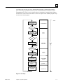
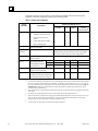
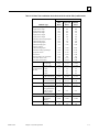
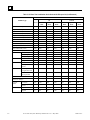
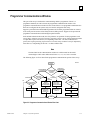
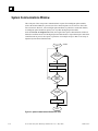
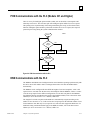
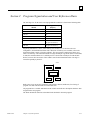
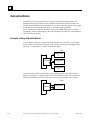
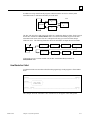
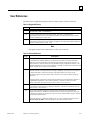
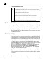
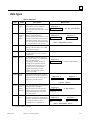
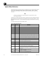
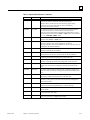
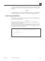
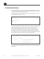
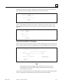
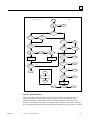
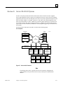
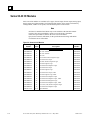
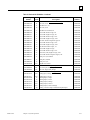
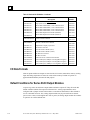
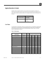
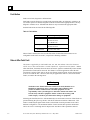
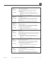
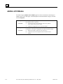
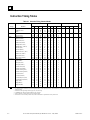
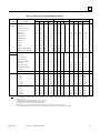
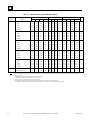
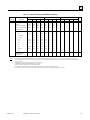
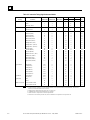
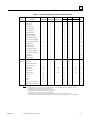
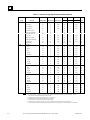
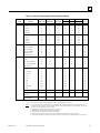
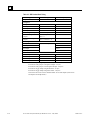
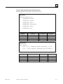
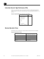
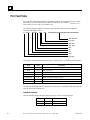
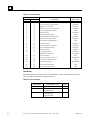
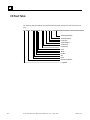
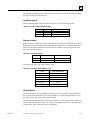
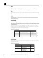
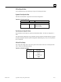
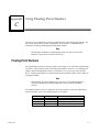
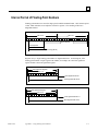
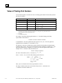
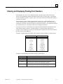
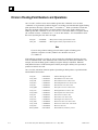
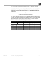
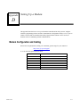
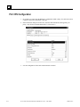
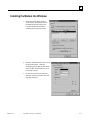
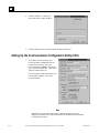
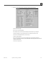
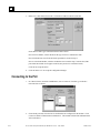
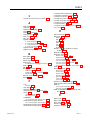
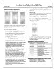


![取扱説明書[PDF:3.6MB]](http://vs1.manualzilla.com/store/data/006628547_3-e54ea06345f6aab36157749c619a5a32-150x150.png)