1
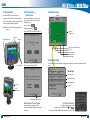
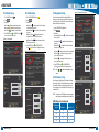
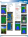
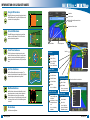
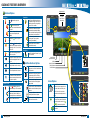
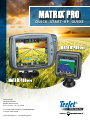
Q u i c k S ta r t - u p G u i d e
TeeJet Technologies
1801 Business Park Drive
Springfield, Illinois 62703 USA
Tel: (217) 747-0235 • Fax: (217) 753-8426
For a complete English User Manual, go to www.teejet.com
or order part number 98-05238
© TeeJet Technologies 2011 ● 98-01380 R0 English-US
Start
Press the POWER BUTTON to power on the console.
Upon power up, the Matrix Pro will begin its Start Up Sequence.
To turn the power off, press and briefly hold the power button until a
confirmation screen acknowledges shut down mode.
WARNING! Wait 30 seconds before restarting the console after
powering off.
USB Port with Rubber Cover
#2 Start New Job or
Continue Job
#3 Guidance Screen
Guidance Bar
Once the power up sequence has completed, the Home
screen will appear with the option to start a new job or
continue an existing job.
0.0 mph
Mark A
0.00 ac
To start a new job press New Job .
To continue the existing job press Continue .
Figure 1-1: MUST HAVE GPS BEFORE STARTING JOB
Status Bar
#1 Turn Power On
Navigation and
Guidance Options
12/14/10 3:52 AM
Home Button
Power Button
Must have valid GPS signal before starting job.
Please wait.
New Job
Home/Job Screen (or press Home Button)
Unit Setup
Vehicle View Guidance
Field View Guidance
RealView Guidance
Continue
#4 Go To Unit Setup
Zoom In/Out Buttons
Figure 1-2: Home Screen with Acquired GPS
12/14/10 3:52 AM
Do you want to start a new job data or continue last job?
The Configuration options will be displayed first. Data Management, Console Setting and Tools can be accessed through the side
tab keys.
Configuration
Vehicle
Implement
AutoSteer
Tilt
Lightbar
GPS
Configuration side tab
Starting a new job will clear the previous job data.
Power Button
New Job
Continue
Video
Side Tab Keys
Data Management side tab
Console Settings side tab
Tools side tab
USB Port
with Rubber Cover
Configuration
RealView Camera Full Screen Video View
RealView Camera Full Screen Video View
View video feed(s) and setup cameras without GPS
available. Options for Realview Guidance are not available
on this screen.
2
www.teejet.com
Light or Dark Console Screen
The console is availalbe in two color schemes.
To change to “dark”, press CONSOLE side tab
. Press Display .
Press Color Scheme DOWN arrow
and select between “Dark” or “Light” color mode.
Vehicle
Implement
AutoSteer
Tilt
Lightbar
GPS
Video
98-01380 R0
3
Configure
#5 Cultural Setup
#6 Vehicle Setup
#7 Implement Setup
1. Press CONSOLE side tab
.
2. Press Cultural .
3. Select from:
– defines the system measurements
►Units
– defines the system language
►Language
– establishes the local time zone.
►Time Zone
1. Press CONFIGURATION side tab
.
2. Press Vehicle .
3. Select from:
– selects the type of vehicle that most
►Vehicle Type
closely represents your vehicle
– sets the height of the antenna from
►Antenna Height
the ground
– sets whether the boom is
►Direction to Boom
located behind or in front of the GPS antenna
– defines the distance from the
►Distance to Boom
GPS antenna to the boom
When a SmartCable or Section Driver Module (SDM) is not
present only a single boom setup is available. Configurations
for Overlap, Delay On and Delay Off will not be available, and
Number of Sections will be set to one.
4. Press RETURN arrow
or CONSOLE side tab
return to the main Console screen.
Figure 1-3: Cultural Options
Console Settings
Display
Cultural
Sound
About
to
or CONFIGURATION
4. Press RETURN arrow
to return to the main Configuration screen.
side tab
Figure 1-4: Vehicle Setup Options
Configuration
Vehicle
Implement
AutoSteer
Tilt
Lightbar
GPS
Video
US
Language
English-US
Time Zone
UTC
Ant Height
Dir to Boom
Dist to Boom
or CONFIGURATION
4. Press RETURN arrow
to return to the main Configuration screen.
side tab
NOTE: Press
or
screens.
Front Wheel
www.teejet.com
Implement
AutoSteer
Tilt
Lightbar
GPS
Video
Config->Implement
Num Sections
15
Guidance Width
75.00 ft
Spray Width
75.00 ft
12.50 ft
Backward
0.00 ft
Config->Implement (2)
Overlap
50%
NOTE: An update of your SCM software may also be required
when updating an existing Matrix console to Matrix Pro.
Delay On
1.00 s
SCM Software Version Required
Delay Off
1.00 s
SCM Software
Version
Matrix 1.x
1.03
●
1.04
●
1.05
●
10.0
4
Vehicle
to switch between Implement setup
When a Steering Control Module (SCM) is present, AutoSteer
options will be available. For detailed setup instructions, refer
to your specific FieldPilot or auto steering installation manual
or visit www.teejet.com for the full Matrix Pro User Manual, part
number 98-05238.
Config-> Vehicle
Vehicle Type
.
1. Press CONFIGURATION side tab
2. Press Implement .
3. Select from:
►Number of Boom Sections # – establishes the number
of boom sections
►Guidance Width
– establishes the width between
guidelines
►Spray Width
– establishes the width of each boom
section for a total spray width
►Overlap
– determines the amount of overlap allowed
– establishes the timing for the boom
►Delay On
section valves to switch on
►Delay Off
– establishes the timing for the boom
section valves to switch off
Configuration
#8 AutoSteer Setup
Console->Cultural
Units
Figure 1-5: Implement Setup Options
Matrix Pro 2.x
●
98-01380 R0
5
Go
#9 Go To Guidance Screen
#10 Choose a Guidance Mode
Figure 1-15: Vehicle View Guidance
1. Press NAVIGATION & GUIDANCE OPTIONS icon
display navigation options.
2. Press GUIDANCE MODE icon
.
3. Select from:
►Straight AB
►Curved AB
►Circle Pivot
►Last Pass
►NextRow
6.0 mph
< 0.0 >
7.6 ac
Figure 1-18: Choose a Guidance Mode
0.0 mph
Mark A
0 ac
Figure 1-16: Field View Guidance
6.0 mph
Mark A
A A
0 ac
#11 Mark A and B Points
to
Figure 1-20: Mark B Point
To establish a AB guideline:
1. Drive to the desired location of Point A
1:14 PM
.
2. Press NAVIGATION & GUIDANCE OPTIONS icon
display navigation options.
Mark B
to
B
3. While the vehicle is in motion, press MARK A icon A .
4. Drive to the desired location of Point B
7.2 mph
.
5. Press MARK B icon B to establish the AB line.
6. “Would you like to name this guideline?”
Press
►Yes – to enter a name and save the guideline in the
console.
►No – to automatically generate a name and save the
guideline in the console.
The console will begin providing navigation information.
NOTE: The MARK B icon B is not available for selection
(grayed out) until the minimum distance is travelled.
Figure 1-21: Save Guideline
1:14 PM
Use CANCEL MARK icon
to cancel the Mark A command
and revert to the previous AB guideline (when established).
> 0.0 <
7.2 mph
Would you like to name this guideline?
To establish additional guidelines, follow the same steps as the
initial guideline.
Figure 1-19: Mark A Point
0.0 mph
6
< 0.0 >
www.teejet.com
0 ac
12:32 PM
Mark A
No
7.2 mph
Figure 1-22: Follow Guidance
Figure 1-17: RealView Guidance
6.0 mph
Mark A
Yes
0 ac
2.73 ac
> 0.0 <
7.2 mph
98-01380 R0
7
information on Guidance Modes
Straight AB Guidance
Straight AB guidance provides straight line guidance based on
A and B reference points. The original A and B point are used
to calculate all other parallel guidelines.
-13
8.9 <
Guidance Bar
7.2 mph
Horizon Compass
Vehicle with Real-time Representation of Active
Boom Sections
Navigation and Guidance Options
Curved AB Guidance
Curved AB Guidance provides guidance along curved lines
based on an initial AB reference line. This initial baseline is
used to calculate all other guidelines.
Navigation Guidelines
Circle Pivot Guidance
Circle Pivot guidance provides guidance around a central
location that radiates inward or outward. It is used for product
application in a center pivot field while being guided along a
circular guideline that matches a center pivot irrigation system
radius.
GPS Status
Painted Coverage Area
-13
8.9 <
7.2 mph
Status Bar
Red = no GPS
Yellow = GPS only
Green = DGPS,WAAS/
RTK, GLONASS
Peach = Glide/ClearPath
Last Pass Guidance
Last Pass Guidance offers true last pass navigation. The
console will automatically detect the nearest “applied” guideline
and establish adjacent pass based on that guideline.
Guidance Mode
Straight AB Guidance
Curved AB Guidance
Circle Pivot Guidance
Last Pass Guidance
NextRow Guidance
NextRow Guidance indicates where the NextRow is located
and provides guidance at row ends to the next adjacent row.
When the operator marks the end of the row and begins
turning to the next row, a Straight AB guidance line is provided
in the next row. When the vehicle is in the NextRow guidance
is turned off.
No Guidance
No Guidance turns off guidance.
8
www.teejet.com
AutoSteer Status
Green = Engaged
Yellow = Enabled
NextRow
Red = Disabled
No icon = No Guidance
No icon = no auto steering
system installed on system
Bounded Area Status
Outside Boundary =
Currently traveling outside
bounded area
Inside Boundary = Currently
traveling inside bounded
area
No icon = No boundary
established
BoomPilot Status
Red = Off/Manual
Green = Automatic
Yellow = All On
No icon = Single Boom
Section (no SmartCable or
SDM installed on system)
Press a Status Bar icon for more information.
-13
8.9 <
7.2 mph
GGA Rate: 5 Hz
VTG Rate: 5 Hz
Num Sats: 10
HDOP: 1
PRN: 135
GGA Quality: 2
Receiver: 1
98-01380 R0
9
Guidance Features Overview
Navigation Activity &
Boom Status
Guidance Options
Guidelines
Boundaries
Mark Boundary. Establishes application area
and determines no apply zones. Boundary is
established to the outside of an applied pass.
Grayed = GPS is unavailable.
Mark A
. Marks the first point of the
guideline.
A
B
Mark B
. Marks the end point of the
guideline. Grayed = minimum distance has not
been traveled.
Finish Boundary. Finalizes boundary process.
Boundaries can also be closed by travelling to
within a swath width of the starting point. Grayed =
minimum distance has not been traveled.
Cancel Mark A. Cancels the Mark A process.
Reverts to previous AB guideline (when
established).
B
NextRow Mark B
the row.
A
Azimuth Degree
. Establishes a straight
guideline measured by degrees clockwise from
a north base line. North = 0, East = 90, South =
180, West = 270.
A
Next Straight AB or Azimuth Degree Guideline.
Shows the next straight guideline saved in the
current job.
Next Curved AB Guideline. Shows the next
Curved AB guideline saved in the current job.
Next Circle Pivot Guideline. Shows the next
Circle Pivot AB guideline saved in the current
job.
Curved Lookahead. Provides an indication of
where the current steering will take the vehicle
using a ‘pointer’ as guidance
Return to Point
Mark Point
. Establishes a point at the
vehicle location. Grayed = GPS is unavailable.
Return to Point. Provides distance back to an
established point. (Switch to Vehicle View to
provide navigation back to an established point.)
Cancel Point. Deletes the Marked Point.
No GPS
1 deg
GPS Status
Cross Track Error
Current Activity
12:32 PM
No GPS
1 deg
Speed
Area
Area
Time
Time
Swath #
Heading
-13
> 0.0 <
Swath #
7.2 mph
Heading
Cancel Boundary. Cancels the new mark
boundary process. Reverts to previous
boundary (when established).
. Marks the end point of
A+ Nudge. Shifts the existing guideline to the
vehicle’s current position.
12:32 PM
Speed
Delete Boundary. Deletes all established
boundaries from current job.
BoomPilot
BoomPilot. Selects BoomPilot mode. Grayed =
GPS is unavailable.
RealView Guidance Options
Video Camera Select. Selects one of up to
eight camera views if a Video Selection Module
(VSM) is attached.
Home/Job Screen
(or press Home Button)
Unit Setup
Vehicle View Guidance
Field View Guidance
RealView Guidance
Split Camera View. Selects one of two sets of
four camera inputs (A/B/C/D or E/F/G/H) to
divide the screen into four separate video feeds.
Guidance Over Video Setup. Access to turn on
Guidance Over Video or Steering Angle and
adjust guidelines.
Guidance Over Video. Places three-dimensional
guidelines over the video feed for navigational
assistance.
Steering Angle. Displays the direction in which
the steering wheel needs to be adjusted.
Up & Down Icons. Used to adjust the guidance
lines to match the camera’s view.
Screen Options
Vehicle View Zoom In/Out. Icons or buttons
adjust the vehicle’s view or perspective to the
horizon from vehicle view to bird’s eye view.
Field View Zoom In/Out. Icons or buttons
increase/decrease the area displayed on the
screen.
Pan. Touching the screen allows operator to
focus on specific map areas without moving the
vehicle. Arrows on screen move the view
in the corresponding direction.
A
A
A
B
World View. Extends screen view to the widest
area available.
10
www.teejet.com
98-01380 R0
11
Guidance Features Details
Figure 1-7: Save Guideline
A A+ Nudge Feature
-13
To adjust a AB guideline to your current location:
1. Press NAVIGATION & GUIDANCE OPTIONS icon
display navigation options.
> 0.0 <
7.2 mph
Would you like to name this guideline?
Yes
A Azimuth Degree
No
To establish the azimuth guideline:
2. Press AZIMUTH icon A to enter azimuth degree.
3. Use the entry screen to establish the Azimuth degree.
4. Press:
to save the settings
►Accept
►Cancel
to leave the keypad without saving
5. “Would you like to name this guideline?”
Press
►Yes – to enter a name and save the guideline.
►No – to automatically generate a name.
The console will begin providing navigation information.
-13
To establish a field boundary:
1. Drive to a desired location at the perimeter of the field/
area.
to
2. Press A+ NUDGE icon A to adjust the guideline to the
current location.
1. Press NAVIGATION & GUIDANCE OPTIONS icon
display navigation options.
Figure 1-10: Save Boundary - Field View
Field Boundary
to
Figure 1-8: Follow Guidance
0 deg
> 0.0 <
7.2 mph
to
2. Press NAVIGATION & GUIDANCE OPTIONS icon
display navigation options.
3. While the vehicle is in motion, press BOUNDARY
.
icon
4. Travel the perimeter of the field/area.
5. Finish boundary:
►Travel to within one swath width of the starting point. The
boundary will close automatically (the white guideline will
turn black).
►Press BOUNDARY FINISH icon . A straight line will
complete the boundary between your current location and
the starting point.
6. Press:
►Yes – to save the boundary.
►No – to delete the boundary.
Mark A
7.2 mph
Area bounded = 14.45 ac
Press “Yes” to save the marked
boundary or “No” to delete the
boundary.
Yes
No
Figure 1-11: Boundaries Complete
-13
Mark A
7.2 mph
Figure 1-9: Boundary in Progress
-13
Mark A
7.2 mph
To establish additional azimuth guidelines, follow the same
steps as the initial azimuth guideline.
Figure 1-6: Azimuth Degree
-13
12
> 0.0 <
If a swath was applied while creating an external or initial
boundary, the boundary line will be to the exterior of the applied
swath. If a swath was applied while creating an interior or
additional boundary, the boundary line will be to the interior of
the applied swath.
7.2 mph
Enter Azimuth (Deg)
1
2
3
Clear
4
5
6
<--
7
8
9
0
.
+/-
www.teejet.com
NOTE: On the external or initial boundary, the BOUNDARY
FINISH icon
is not available for selection (grayed
out) until the minimum distance is travelled (five-times
the swath width).
To create an interior boundary, follow the same steps as the
initial boundary.
to cancel the new field
Use CANCEL BOUNDARY icon
boundary process and revert to the previous boundary (when
established).
Use DELETE BOUNDARY icon
for the current job.
to delete all field boundaries
In correspondence to your current location, the IN BOUNDARY
icon
or OUT BOUNDARY icon
is displayed on the
Status Bar once the boundary is established.
98-01380 R0
13
Matrix
FieldPilot
BoomPilot
Optional Accessory
To show other saved guidelines:
1. Drive to the desired location of Return Point
.
2. Press NAVIGATION & GUIDANCE OPTIONS icon
display navigation options.
to
.
1. Press NAVIGATION & GUIDANCE OPTIONS icon
display navigation options.
GPS Antenna
78-50155
78-50190 w/GLONASS
to
Figure 1-13: Next Guideline
Figure 1-12: Return Point Established - Vehicle View
Mark A
-13
8 Pos.
45-05765 8 Pos.
Speed/Sense Cable
.
2. Press NEXT GUIDELINE icon
32-50008
Switch
Speed Cable
16-00022 RealView Camera
Mark A
+12V
Camera
7.2 mph
1.7 mph
RS-232
TJ CAN
(Terminated)
45-07703
SCM Power I/O
SCM Power I/O
45-07703
DC: xx/xx
Power
78-08075
Steering Control
Module (SCM)
CAN
45-08117 CAN Extension Cable 20'/6m
GPS In
COM 1
45-10103
DC: xx/xx
Name: Stream Edge
Total: 4
14
.
to delete the
www.teejet.com
CAN Tee
45-08117 CAN Extension Cable 20'/6m
3A Fuse
Engage / Disengage
32-04020
DC: xx/xx
91-07011
Steering
Wheel
Switch
Kit
BoomPilot
Harness
Part number
dependent on
Rate Controller
32-04040
Remote
Engage/
Disengage
Switch
32-04020
Optional
Footswitch
45-10103
Harness
Steering
(A+B)
To show distance and guidance to the established point:
Use CANCEL RETURN TO POINT icon
established point.
45-07716
DC: xx/xx
POWER IN
Pattern: Curved AB
2. Press the RETURN TO POINT icon
Remote
Steering Valve
Co
nn
(+ ecto
12
v) to
1. Press NAVIGATION & GUIDANCE OPTIONS icon
display navigation options.
Tilt Gyro Module
CAN Harness
78-08076
Articulated
Gyro Module
(AGM)
78-08072
Voltage
Regulator
45-05381
DC: xx/xx
45-05381
Battery
12'/3m
w/15 Amp
Fuses
Engage/Disengage
7.2 mph
Seat Sensor
FieldPilot Interface
78-08072
DC: xx/xx
Mark A
45-07716
Tilt Gyro Module (TGM)
Harness
GPS Power
Figure 1-14: View Which Guideline is Active
-13
SCM COM 2
Steering
Wheel Sense
1.7 mph
45-05626
Power/CAN/Data
Cable
(included with
FieldPilot
and BoomPilot kits)
45-07708
SCM Harness
Valve Output
457 ft
CAN
to RS-232
To view which guideline is active, press the Guidance Mode icon
on the Status Bar.
Kit, RAM Mount
w/Suction Cup
90-02349
(Matrix Pro 570G)
90-02700
(Matrix Pro 840G)
45-05617: 20'/6m
45-05618: 60'/18m
Camera Extension Cable
78-08068: 8CH
78-08067: 4CH
Video Selector Module, CAN
A A A
8:53 AM
5 Pos.
8 Pos.
Power/DATA
45-05626
3. Press ADD POINT icon
8:21 AM
45-05786: 20'/6m
45-05787: 30'/9m
Antenna Cable
Next Guideline
To mark a return point:
Matrix Pro 840G
75-30084
75-30090 w/GLONASS
Matrix Pro 570G
75-30082
75-30083 w/GLONASS
65-05226
Kit, Bracket
RXA-30 Antenna
System Diagram
Return to Point
78-50187
Optional RXA-30
GPS Antenna
Rate Controller
Remote ABSC
Status Switch
Connection
78-05077
BoomPilot Section Driver Module
(15 sections)
to
Steering
Valve
Valves
Console
Harness
98-01380 R0
15