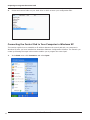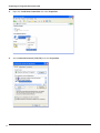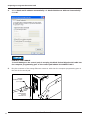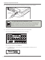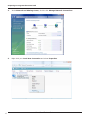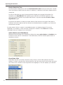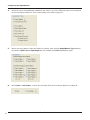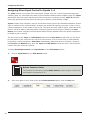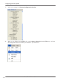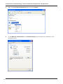
1
Control Pad Configuration
Software Manual
2562418C
REV. C 411
Printed in U.S.A.
Arjent®, Legend®, Raydian®, SmartSiren®, Solaris®, Impaxx®, and Viper® are registered trademarks of Federal Signal Corp.
Convergence is a trademark of Federal Signal Corporation.
Pentium® is a registered trademark of Intel Corporation.
Windows® is a registered trademark of Microsoft Corporation in the United States and other countries.
InstallShield is a registered trademark and/or service mark of InstallShield Corporation.
Table of Contents
CHAPTER 1 Safety Messages...................................................................... 7
Safety Messages to Users of This Software.............................................................................7
Safety Messages to Installers of Federal Signal Electronic Sirens and Sound/Light Systems...........7
CHAPTER 2 Preparing to Program the Control Pad................................... 10
System Requirements........................................................................................................ 10
Installing the Software....................................................................................................... 11
Connecting the Control Pad to Your Computer in Windows XP.................................................. 12
Connecting the Control Pad to Your Computer in Windows Vista/7............................................ 16
CHAPTER 3 Exploring the Interface.......................................................... 21
An Overview of the SmartSiren Platinum Configuration Software............................................. 21
Application Header............................................................................................................ 23
Minimize Window (–) Button and Close Program (X) Buttons................................................... 23
Connection Status Pane..................................................................................................... 23
The Four Programming Modules.......................................................................................... 24
The Button Configuration Module.................................................................................... 24
The Button Selection Module.......................................................................................... 25
SignalMaster and Warn Buttons.................................................................................. 25
Slide Switch Buttons.................................................................................................. 26
The Device Selection Module.......................................................................................... 26
Device Selection Tabs................................................................................................ 27
Option Buttons and Checkboxes.................................................................................. 27
Drop-Down Lists....................................................................................................... 27
Escape Button.......................................................................................................... 28
The Button Control Module............................................................................................ 28
Inputs 1 to 4....................................................................................................................29
Horn Ring........................................................................................................................30
File Transfer Status Panes.................................................................................................. 30
Uploading Configuration Files......................................................................................... 30
Downloading Configuration Files..................................................................................... 30
CHAPTER 4 Configuring the Lightbar........................................................ 34
An Overview of the Lightbar Pane........................................................................................ 34
Lightbar Default Settings.................................................................................................... 35
Assigning Lightbar Functions to Buttons............................................................................... 35
Linking Buttons to Slide Switch Positions (Lightbar Pane)........................................................ 39
CHAPTER 5 Configuring the SignalMaster................................................. 44
An Overview of the SignalMaster Pane................................................................................. 44
SignalMaster Default Settings............................................................................................. 45
Assigning SignalMaster Control to the SignalMaster Button..................................................... 46
3
SmartSiren Platinum Series
Table of Contents
Assigning SignalMaster Control to the Warn Button................................................................ 48
Assigning SignalMaster Control to Buttons 1 to 15 and Inputs................................................. 51
Assigning SignalMaster Control to the Slide Switch................................................................ 54
CHAPTER 6 Configuring the Siren............................................................. 59
An Overview of the Siren Pane............................................................................................ 59
Siren Default Settings........................................................................................................ 60
Siren Functions for Buttons 1–15........................................................................................ 60
Siren Functions for Slide Switch 1–3.................................................................................... 63
Siren Input Control for Inputs 1–4....................................................................................... 66
CHAPTER 7 Configuring the Internal Relays............................................. 71
An Overview of the Internal Relays...................................................................................... 71
Relay Default Settings....................................................................................................... 72
Configuring the Internal Relays (Buttons 1 to 15 and Inputs).................................................. 72
Configuring the Internal Relays for the Slide Switch Buttons................................................... 76
CHAPTER 8 Configuring the External Relay.............................................. 81
An Overview of the External Relay....................................................................................... 81
Configuring the External Relay............................................................................................ 82
Configuring the External Relay for the Slide Switch Buttons.................................................... 85
CHAPTER 9 Configuring the ILS System................................................... 89
An Overview of the ILS System........................................................................................... 89
Configuring the ILS System................................................................................................ 90
Configuring the ILS System for the Slide Switch Buttons........................................................ 93
CHAPTER 10 Completing the Control Pad Configuration........................... 98
Final Steps in Completing the Configuration.......................................................................... 98
Saving Your Completed Configuration File............................................................................. 98
Printing a Record of Your Configuration File........................................................................... 99
Uploading the Configuration File to the Control Pad.............................................................. 101
Putting the Control Pad into Operation Mode....................................................................... 101
Testing the SmartSiren Platinum System............................................................................ 102
APPENDIX.............................................................................................. 103
Troubleshooting Your IP Connection in Windows XP.............................................................. 103
Resetting the IP Address in Windows XP............................................................................. 105
Troubleshooting Your IP Connection in Windows Vista/7........................................................ 108
Resetting Your IP Address in Windows Vista/7..................................................................... 110
The Default Configuration................................................................................................. 115
Button Layout Worksheet................................................................................................. 116
4
SmartSiren Platinum Series
Table of Contents
Tables of Functions
Button Control Capabilities.......................................................................................................... 31
Menu Commands.......................................................................................................................32
Lightbar Auxiliary Functions........................................................................................................ 42
SignalMaster Types....................................................................................................................57
SignalMaster ILS Directional Patterns........................................................................................... 58
Fast and Low Power Options........................................................................................................ 58
Siren Function (Buttons 1–15)..................................................................................................... 69
Siren Control (Buttons 1–15)...................................................................................................... 69
Siren Control (Horn Ring)........................................................................................................... 69
Siren Control (Inputs 1–4).......................................................................................................... 70
Siren Control (Slide Switch 1–3).................................................................................................. 70
Pins for Internal Solid State Relay................................................................................................ 79
Switch Positions for Internal Solid State Relays . ........................................................................... 79
Flash Functions for Perimeter Lights: Internal Relays...................................................................... 80
Flash Functions for Perimeter Lights: External Relay ...................................................................... 88
ILS System Functions................................................................................................................. 97
5
SmartSiren Platinum Series
6
CHAPTER 1
Safety Messages
Safety Messages to Users of This Software
People’s lives depend on your safe installation and usage of Federal Signal products. It is
important to read, understand, and follow all instructions shipped with the products. In
addition, listed below are some other important safety instructions and precautions you
should follow:
• The SmartSiren® Platinum enables installers to easily change the configuration and functions of
the sound and light warning systems of an emergency vehicle. To avoid configuration errors, it is
important to carefully read this manual before using this software.
To help you plan your configuration, use the worksheet is on page 116.
Failure to follow all safety precautions and instructions may result in property damage,
serious injury, or death to you or others.
Safety Messages to Installers of Federal Signal Electronic Sirens and
Sound/Light Systems
People’s lives depend on your proper installation and servicing of Federal Signal products. It
is important to read and follow all instructions shipped with this product. In addition, listed
below are some other important safety instructions and precautions you should follow:
Before Installation
Qualifications
• To properly install an electronic siren you must have a good understanding of automotive electrical
procedures and systems, along with proficiency in the installation and service of safety warning
equipment. Always refer to the vehicle’s service manuals when performing equipment installations on
a vehicle.
Sound Hazards
• Your hearing and the hearing of others, in or close to your emergency vehicle, could be damaged
by loud sounds. This can occur from short exposures to very loud sounds, or from longer exposures
to moderately loud sounds. For hearing conservation guidance, refer to federal, state, or local
recommendations. OSHA Standard 1910.95 offers guidance on “Permissible Noise Exposure.”
7
SmartSiren Platinum Series
Safety Messages
All effective sirens and horns produce loud sounds (120 dB) that may cause permanent hearing loss.
Always minimize your exposure to siren sound and wear hearing protection. Do not sound the siren
indoors or in enclosed areas where you and others will be exposed to the sound.
• Federal Signal siren amplifiers and speakers are designed to work together as a system. Combining
a siren and speaker from different manufacturers may reduce the warning effectiveness of the siren
system and may damage the components. You should verify or test your combination to make sure
the system works together properly and meets federal, state and local standards or guidelines.
During Installation
• Do NOT get metal shavings inside the product. Metal shavings in the product can cause the system
to fail. If drilling must be done near the unit, place an ESD-approved cover over the unit to prevent
metal shavings from entering the unit. Inspect the unit after mounting to be sure there are no
shavings present in or near the unit.
• Do NOT connect this system to the vehicle battery until ALL other electrical connections are made,
mounting of all components is complete, and you have verified that no shorts exist. If wiring is
shorted to vehicle frame, high current conductors can cause hazardous sparks resulting in electrical
fires or flying molten metal.
• To avoid a battery explosion, always disconnect the negative battery cable first and reconnect it last.
Avoid causing a spark when connecting near tot to the battery. The gases produced by a battery can
cause a battery explosion that could result in vehicle damage and serious injury.
• Be sure the siren amplifier and speaker(s) in your installation have compatible wattage ratings.
• In order for the electronic siren to function properly, the ground connection must be made to the
NEGATIVE battery terminal.
• Sound output will be severely reduced if any objects are in front of the speaker. If maximum sound
output is required for your application, you should ensure that the front of the speaker is clear of any
obstructions.
• Install the speaker(s) as far forward on the vehicle as possible, in a location which provides maximum
signaling effectiveness and minimizes the sound reaching the vehicle’s occupants. Refer to the
National Institute of Justice Guide 500-00 for further information.
• Mounting the speakers behind the grille will reduce the sound output and warning effectiveness of
the siren system. Before mounting speakers behind the grille, make sure the vehicle operators are
trained and understand that this type of installation is less effective for warning others.
• Sound propagation and warning effectiveness will be severely reduced if the speaker is not facing
forward. Carefully follow the installation instructions and always install the speaker with the projector
facing forward.
• Do NOT install the speaker(s) or route the speaker wires where they may interfere with the operation
of airbag sensors.
• Installation of two speakers requires wiring speakers in phase.
• Never attempt to install aftermarket equipment, which connects to the vehicle wiring, without
8
SmartSiren Platinum Series
Safety Messages
reviewing a vehicle wiring diagram available from the vehicle manufacturer. Insure that your
installation will not affect vehicle operation and safety functions or circuits. Always check vehicle for
proper operation after installation.
• Do NOT install equipment or route wiring or cord in the deployment path of an airbag.
• If a vehicle seat is temporarily removed, verify with the vehicle manufacturer if the seat needs to be
recalibrated for proper airbag deployment.
• Locate the control head so the vehicle, controls, and microphone can be operated safely.
• When drilling into a vehicle structure, be sure that both sides of the surface are clear of anything that
could be damaged.
After Installation
• After installation, test the siren system and light system to ensure that it is operating properly.
• Test all vehicle functions, including horn operation, vehicle safety functions and vehicle light systems,
to ensure proper operation. Ensure that the installation has not affected vehicle operation or changed
any vehicle safety function or circuit.
• After testing is complete, provide a copy of these instructions to the instructional staff and all
operating personnel.
• File these instructions in a safe place and refer to them when maintaining and/or reinstalling the
product.
Failure to follow all safety precautions and instructions may result in property damage,
serious injury, or death.
RETAIN AND REFER TO THESE MESSAGES
9
SmartSiren Platinum Series
CHAPTER 2
Preparing to Program the Control Pad
PRECAUTIONS FOR CONFIGURING THE SmartSiren Platinum CONTROL PAD
Property damage, serious injury, or death may result if the SmartSiren Platinum control
pad is improperly configured. Configuration is to be performed at the time of the software
installation. It is NOT intended for operators to “customize” the operation of the control pad
for their individual preferences. It is the installer’s responsibility to determine compatibility,
suitability, and ensure proper programming of the system. In addition, the person responsible
for programming MUST be familiar with local codes and procedures for the safe operation of
emergency-vehicle siren and lights.
System Requirements
The SmartSiren Platinum Configuration Software is supported on laptops and desktops meeting these
minimum requirements:
• 1 GHz Pentium® 3 processor or compatible (32-bit and 64-bit)
• Microsoft Windows® XP with Service Pack 2, Windows Vista or Windows 7 (32-bit and 64-bit versions)
• 512 MB RAM for Windows XP
1 GB RAM for Windows Vista and Windows 7
Depending on your system, more memory may be required.
• 15 MB available disk space
• 1024 x 768-pixel monitor resolution, 16-bit display (32-bit recommended)
• CD-ROM drive
• One free RJ-45 Ethernet port for connection to the SmartSiren Platinum control pad with the included
Ethernet cable (Federal Signal part number 1751532)
This chapter explains how to install the SmartSiren Platinum Configuration Software on your computer.
It also explains how to establish an IP address between the control pad and your computer in
Windows XP, Windows Vista and Windows 7. A local area connection (LAN) is not needed because the
SmartSiren Platinum Configuration software creates a network between your computer and the control
pad. Finally, the chapter walks you through the process of setting up the control pad for programming.
To wire the control pad for 12 Vdc power, which is needed for programming, refer to the SmartSiren
Platinum Installation, Maintenance, and Service manual, document number 2562502 or the Quick
Connect Guide, document number 2562417.
10
SmartSiren Platinum Series
Preparing to Program the Control Pad
Before you begin programming the SmartSiren Platinum control pad, read this manual to understand
the programming process and decide how you want the control pad to operate. To help you plan your
configuration, a worksheet provided in the appendix on page 116. After you finish programming the
control pad, you can also print a copy of each configuration window. See “Printing a Record of Your
Configuration File” on page 99.
Installing the Software
To install the control pad configuration software:
1.
Close all applications that are running on your computer.
Uninstall the SmartSiren Platinum Configuration Software
TE
O
N
11
If you have a version of the SmartSiren Platinum software installed on your
computer, uninstall the software before installing the latest version by selecting
Start > Control Panel > Add or Remove Programs > SmartSiren Platinum
3000 > Remove.
2.
Insert the SmartSiren Platinum Series CD into your CD or DVD drive.
3.
When the InstallShield® Wizard appears, click Next to continue. Follow the on-screen instructions
to complete the installation. If the InstallShield Wizard does not appear automatically, navigate
to the CD-ROM drive and double-click setup.exe. If you are using Windows Vista, right-click
setup. exe and choose Run as Administrator.
SmartSiren Platinum Series
Preparing to Program the Control Pad
4.
Create and name a folder on your hard drive in which to store your configuration files.
Connecting the Control Pad to Your Computer in Windows XP
This section explains how to establish an IP address between the control pad and your computer in
Windows XP after you have installed the SmartSiren Platinum Configuration Software. The network you
create by following the steps in this section enables you to program the control pad.
1.
12
In the Start menu click Connect to and select Open.
SmartSiren Platinum Series
Preparing to Program the Control Pad
13
2.
Right-click Local Area Connection and select Properties.
3.
Select Internet Protocol (TCP/IP) and click Properties.
SmartSiren Platinum Series
Preparing to Program the Control Pad
4.
Select Obtain an IP address automatically and Obtain DNS Server Address Automatically.
Click OK.
CONTROL PAD DAMAGE
To avoid damage to the control pad, do not plug the black Federal Signal serial cable into
the computer programming port on the control pad labeled PC CONNECT ONLY.
5.
Plug the connector of the orange Ethernet crossover cable into the computer programming port on
the side of the control pad.
ORANGE
ETHERNET CABLE
(P/N 751532)
PROGRAMMING
PORT ON
CONTROL PAD
14
SmartSiren Platinum Series
Preparing to Program the Control Pad
6.
Plug the other end of the cable into the RJ-485 Ethernet connector on your computer.
ETHERNET
(RS-485) PORT
ORANGE ETHERNET CABLE
(P/N 1751532)
The control pad must be connected to 12 Vdc
TE
O
N
7.
To establish the Ethernet connection in the next step, the control pad must be
wired for 12 Vdc power. For connection instructions, refer to the SmartSiren
Platinum Installation, Maintenance, and Service manual, document number
2562502 or the Quick Connect Guide, document number 2562417.
Set up the control pad for programming by putting it into Program Mode:
a) Press and hold Button 6 while powering up the control pad.
6
b) During the long beep, release Button 6.
c) Press Button 6 again. The first LED on the control pad lights to indicate you are in
Programming Mode.
15
SmartSiren Platinum Series
Preparing to Program the Control Pad
d) Press Button 13. In approximately 30 seconds the first LED blinks and the control pad beeps
to indicate that your Ethernet port is on.
13
If you cannot connect to the Convergence Network, refer to the troubleshooting instructions in the
appendix on page 103.
Connecting the Control Pad to Your Computer in Windows Vista/7
This section explains how to establish an IP address between the control pad and your computer in
Windows Vista and Windows 7 after you have installed the SmartSiren Platinum Configuration Software.
The network you create by following the steps in this section enables you to program the control pad.
1.
16
In the Start menu, right-click Network and select Properties.
SmartSiren Platinum Series
Preparing to Program the Control Pad
17
2.
In the Network and Sharing Center, click the link Manage Network Connections.
3.
Right-click your Local Area Connection and select Properties.
SmartSiren Platinum Series
Preparing to Program the Control Pad
18
4.
Select Internet Protocol Version 6 and click Properties.
5.
Select Obtain an IPv6 address automatically and click OK.
SmartSiren Platinum Series
Preparing to Program the Control Pad
CONTROL PAD DAMAGE
To avoid damage to the control pad, do not plug the Federal Signal serial cable into
the computer programming port on the control pad labeled PC CONNECT ONLY.
6.
Plug the connector of the orange Ethernet crossover cable into the computer programming port
on the side of the control pad.
ORANGE
ETHERNET CABLE
(P/N 751532)
PROGRAMMING
PORT ON
CONTROL PAD
7.
Plug the other end of the cable into the RJ-485 Ethernet connector on your computer.
ETHERNET
(RS-485) PORT
ORANGE ETHERNET CABLE
(P/N 1751532)
The control pad must be connected to 12 Vdc
TE
O
N
19
To establish the Ethernet connection in the next step, the control pad must be
wired for 12 Vdc power. For connection instructions, refer to the SmartSiren
Platinum Installation, Maintenance, and Service manual, document number
2562502 or the Quick Connect Guide, document number 2562417.
SmartSiren Platinum Series
Preparing to Program the Control Pad
8.
Set up the control pad for programming by putting it into Program Mode:
a) Press and hold Button 6 while powering up the control pad.
6
b) During the long beep, release Button 6.
c) Press Button 6 again. The first LED on the control pad lights to indicate you are in
Programming Mode.
d) Press Button 13. In approximately 30 seconds the first LED blinks and the control pad beeps
to indicate that the Ethernet port is on.
13
If you cannot connect to the Convergence Network, refer to the troubleshooting instructions in the
appendix on page 108.
20
SmartSiren Platinum Series
CHAPTER 3
Exploring the Interface
An Overview of the SmartSiren Platinum Configuration Software
The SmartSiren Platinum 3000 Configuration Software is a Microsoft Windows-based application that
enables you to configure how the SmartSiren Platinum control pad and SmartSiren Platinum amplifier
operate the Federal Signal warning devices installed in an emergency vehicle. The serial and non-serial
controlled warning devices operate as part of a system that communicates though the Federal Signal
in-vehicle Convergence™ Network. The devices include:
• SmartSiren Platinum Siren Amplifier/Relay Module
• Model 660100 RS485 Relay Module/Two Channel Flasher
• Lightbars and SignalMaster™ directional/warning lights
• Exterior and interior perimeter warning lights
• Siren, PA, radio, horn-ring transfer
• Automatically activated and timed switches and relays
With the control pad serving as the command center, the SmartSiren Platinum Siren Amplifier/Relay
Module acts as the communications hub of the Convergence Network. With solid-state relays and LEDs
that light to indicate signal transmission between circuits, the siren amplifier does more than amplify
sound. It coordinates the operation and communication of all devices on the network according to the
configuration file you created using the configuration software.
The configuration software displays a GUI (graphical user interface) version of the SmartSiren Platinum
control pad. The interface also includes programmable button-control versions of the four input relays
and horn ring circuit in the SmartSiren Platinum Siren Amplifier. The software enables you to easily
choose what functions the buttons control and how devices and buttons operate without having to
determine logic or perform complicated rewiring.
The application stores the configuration information in a file on your hard drive in a location of your
choice. You can create and name additional configuration files for uploading to the same or other
SmartSiren Platinum control pads. For easy reference, you can also print the screen version of your
system configuration. The elements that make up the interface are illustrated below and described in the
next pages.
21
SmartSiren Platinum Series
Exploring the Interface
Application Header with file name
(page 23)
Close Program Button
(page 23)
Button Selection Module
(page 25)
Button Configuration Module
(page 24)
Device Selection Tab
(page 27)
Minimize Window Button
(page 23)
Connection Status Pane
(page 23)
Inputs 1 to 4
(page 29)
Horn Ring Transfer
(page 30)
Checkbox
(page 27)
Escape Button
(page 28)
Option Button
(page 27)
File Transfer Status
(page 30)
Button Control Module
(page 28)
22
Timer Drop-Down List
(page 27)
Device Selection Module
(page 26)
SmartSiren Platinum Series
Exploring the Interface
Application Header
The application header at the top of the window displays the file name for the file you open The example
below displays the name of the default configuration file (Default.scc) included with the software that
you will modify for your requirements.
Minimize Window (–) Button and Close Program (X) Buttons
One of the first things you will recognize is the Minimize Window button and the Close Program
button in the upper right corner of the interface.
The Minimize (–) button works the same way as it does in other Microsoft Windows-based applications.
By clicking the button, you shrink the window to an icon on the taskbar. This enables you to tuck away
the application without closing it. When you are ready to work with the application, you can quickly
access it by clicking the icon.
The Close Program (X) button works the same as its counterpart in other Windows applications. When
you are ready to close the application, click the button. Click Yes or No in the pop-up box in response to
the question “Do you want to save changes to configuration?” In the dialog box that appears in response
Yes, select a folder for the configuration file, type a new file name, then click Save.
Connection Status Pane
The Connection Status Pane in the upper right corner is the first
pane to check when using the application. It tells you if the control
pad is connected to the Convergence Network. It also displays the
firmware version of the control head, and the date and time of the last
saved configuration file. The control pad, however, must be connected
and powered up to read in a configuration file from your computer. For
information on the system’s wiring, refer to the SmartSiren Platinum
Installation, Maintenance, and Service manual, document number
2562502 or the Quick Connect Guide, document number 2562417.
23
SmartSiren Platinum Series
Exploring the Interface
If the control head firmware is incompatible with the version of the configuration software that you are
using, an error message appears.
For customer support, please call:
Service Department
Federal Signal Corporation
Phone: 1-800-433-9132
Fax: 1-800-343-9706
Email: [email protected]
7 a.m. to 5 p.m., Monday through Friday (CT)
The Four Programming Modules
The SmartSiren Platinum is contained within an integrated workspace, which means each programming
module is displayed within a larger window. The four programming modules are: the Button
Configuration Module, the Button Selection Module, the Device Selection Module, and the
Button Control Module. The default configurations are listed in the chapters for each Device
Assignment Pane. In addition, the appendix has a table on page 116 of the default configurations for
every button.
The Button Configuration Module
The Button Configuration Module displays all devices
available in the Convergence Network, It also displays
functions assigned to the devices that are controlled the
button shown in the header. The Button Configuration
Module also displays device assignments for the four Input
circuits and the Horn Ring Transfer circuit as well.
The information is arranged in a directory tree. To expand
information about a device, click the plus sign (+) next to it.
To collapse the category, click the negative sign (–).
If the tree extends beyond the bottom of the module, a scroll
bar appears to the right. Click and hold the bar, then drag it
up and down to see the entire tree.
The illustration on the right displays the default settings for
Button 8. The button is configured to act as a Push On/
Off switch. When the button is pressed, the perimeter lights
connected to Relay 8 stay on without flashing (Steady On).
The circuit is supplying +12 Vdc during its “on” state (Active
High) and is open during its “off” state (Open Off).
24
SmartSiren Platinum Series
Exploring the Interface
The Button Selection Module
The module is the software version of the 17 buttons and three slide-switch positions on the control
pad. It also has “virtual” buttons representing the four Input circuits and the Horn Ring Transfer
circuits available in the SmartSiren Platinum Siren Amplifier. The Button Selection Module is the
starting point; you must first click a button to make the other options in the Device Selection
Module available for selection.
Corresponds to
control pad
Corresponds to
circuit connections
on the rear of the
SmartSiren Platinum
Siren Amplifier
When you assign a function to a button in the Device Selection Module, the
name of the button and the assigned function are displayed in the directory
tree in the Button Configuration Module (page 24). Functions include
devices, such as lightbars and sirens, and the way the devices operate. You
can assign up to ten functions to all buttons except Slide Switch Position 3,
which has a limit of 20 functions.
You can easily change the name of any button by right-clicking it, dragging the cursor over the
default name to highlight it, and typing a new name. The number of characters, including spaces,
are limited by the size and shape of the buttons. Specifically, the SignalMaster and Warn buttons,
and Buttons 1–15, are limited to 40 characters. The Slide Switch buttons are limited to 44
characters, and the Input buttons are limited to 24 characters.
Although most buttons work the same, some buttons are dedicated to certain devices or have
additional options. These buttons are the SignalMaster and Warn buttons, the Slide Switch
buttons, and buttons that also function as timers, which are described in the next three sections.
Button control for these unique buttons are discussed further in “The Button Control Module” on
page 28. See also “Button Control Capabilities” on page 31.
SignalMaster and Warn Buttons
You can assign a device to any of the buttons except the SignalMaster and Warn buttons in the
upper left corner. The buttons are dedicated to SignalMaster-equipped lightbars or standalone
SignalMaster lightbars. The SignalMaster Pane in the Device Selection Module has options
assignable to these buttons. For more information, see “Chapter 5: Configuring the SignalMaster”
on page 44.
25
SmartSiren Platinum Series
Exploring the Interface
Slide Switch Buttons
The three Slide Switch buttons correspond to the slide switch positions on the control pad. Each
position acts as a momentary switch that turns on and off devices assigned to them. To program
the slide switch to operate as a progressive switch, assign the same functions from the previous
slide switch position to the next position, then add new functions. Up to ten functions can be
assigned directly to Slide Switch 1 and 2, and up to twenty to Slide Switch 3.
In addition, Buttons 1 to 5 and Buttons 14 and 15 can be programmed to activate when
the operator puts the slide switch into a position linked to one or more of these buttons. This
feature enables the operator to turn functions on and off or skip steps in selecting a step-through
SignalMaster warn or directional pattern without changing the position of the slide switch. Linking
a button also extends the number of assignable functions available to a slide switch button with
the additional 10 functions of the linked button. The pane below shows the buttons available for
activation when a slide switch button is selected.
The Device Selection Module
The Device Selection Module is where you assign devices and functions to the buttons in the
Button Selection Module. The devices, identified by tabs at the top of their panes are: Lightbar,
SignalMaster, Siren, Relay, External Relay, and ILS System. The functions determine how and
what they turn on, operate, and turn off. By default, each time you launch the application, it opens
with the Lightbar pane. The pane that is ready for configuration moves in front of the other panes.
The lightbar pane and the others behind it, however, are not active, and therefore not configurable,
until you click a button in the Button Selection Module.
Select a tab to access a device. The tab is
lighter in color to indicate that the pane
available for configuration. The orange bar
is added in Windows XP.
The flow of the selection
process is right to left. Click
a box or option button to
select or deselect.
Esc is green to indicate
the pane is active and can
accept your selections
Options are dimmed
until you select a device
Options are grouped
by device, function,
and similarity.
26
Buttons for activation by a slide
switch position appear when a slide
switch button is selected.
SmartSiren Platinum Series
Exploring the Interface
Device Selection Tabs
To select a pane in background, click the Device Selection Tab on the top of the pane. The tab
of an active pane is lighter than the others. In addition, in Windows XP the tab is topped with an
orange bar
To help you find what you need, devices and their functions are grouped by similarity. For
example, in the SignalMaster Pane lightbar types, SAE and non-SAE warn patterns, and
speed and dimming options are grouped within boxes. A gap also separates Front and Rear
SignalMaster types.
In general, the direction in which you select items is from devices on the right of the pane to
functions on the left. Options that are dimmed and disabled become available as you select the
devices that use them.
In some panes a device or option is unavailable because it is already assigned. To prevent
duplication, for example, a siren tone that is assigned to a button in the Siren Pane remains
unavailable until you reassign it to a new button.
Option Buttons and Checkboxes
Most devices and functions are selected by clicking the empty option button or checkbox next
to them to insert a dot or a checkmark. To de-select them, click the selected option button or
checkbox to clear it.
Drop-Down Lists
Drop down lists are for functions that have many choices, such as flash patterns and timer
settings. To select a function from a drop-down list, click the arrow next to the list box and move
your cursor over a function in the drop-down list to highlight it. The box displays your selection.
27
SmartSiren Platinum Series
Exploring the Interface
Escape Button
When you click a button in the Button Control Module for the first time,
the legend Esc on the Escape button in the upper right corner of the Device
Selection Module changes from gray to green. The change in color lets you
know that the pane is active and ready for your selections.
The Escape button enables you to cancel your changes in
a pane while returning you to the Lightbar Pane. You can
also use the button to deselect default settings or your saved
settings in a pane with one click.
To cancel your changes in a pane after clicking the Escape
button, click OK in the Saving Button Configuration pop-up.
To keep your selections, click Cancel or the X in the popup.
The Button Control Module
The Button Control Module enables you to select how a button operates when pressed. See also
“Button Control Capabilities” on page 31.
28
•
as a Momentary button that turns on a function when pressed and held, and turns off the
function when released.
•
as a Push On/Off button that turns on a function when
pressed and turns off the function when pressed again.
•
as an Exclusive button that turns on a function when
pressed and turns off the button that was pressed
previously in the same row.
•
as a Security Timer that requires the sequential press of
two buttons to turn on a function that turns off after a set
duration. The first button, which is the Security Timer,
must be selected from the buttons with the capability
shown in the table on page 31. The drop-down list of timer
durations has a choice of 4, 8, 12, 16, and 20 seconds.
To turn on the security timer, Button 14, which is the
second “enable” button, must be pressed within 4 seconds
after the first button is pressed. If Button 14 controls
another function, such as a lightbar flash pattern, a second
press of Button 14 turns on the function.
To turn off the Security Timer, press the first button again or let it time out.
•
as a Timer with a set duration for a function to stay on. The durations are the same as for the
Security Timer.
SmartSiren Platinum Series
Exploring the Interface
The Button Control Module is not available for:
•
the SignalMaster button because the button acts as a Push On/Off switch that controls the
default step-through warning patterns. The button controls only the “step-through” selection
of the Left, Right, Center Out directional patterns. A step-through button activates a flash
pattern, siren tone, or other function in a sequence each time you press it, starting with the first
function.
•
the SignalMaster Warn button because the it functions as a Push On/Off switch that selects
one warn pattern or functions as a button that steps through the assignment of two or more
warn patterns.
•
the slide switch because each switch position acts as a momentary button.
Inputs 1 to 4
You can assign to the Input buttons any of the devices and functions in the Device Selection Module.
Each input button corresponds to one of the four input connections on the back of the SmartSiren
Platinum Siren Amplifier. The connections are located below the pins for the discrete SignalMaster.
Input 1 and 2 are active-low inputs that activate a switch when pulled to ground. Input 3 and 4 are
active-high inputs that activate a switch when pulled to 12 Vdc battery voltage. The inputs are most
commonly used for switches that send a signal to the SmartSiren Platinum system when a condition in
the vehicle changes. Changes may include the opening of a trunk or door, a rise in vehicle temperature,
or the release of a gun lock.
SM
+12v
Inputs 1 to 4 (gray)
on back of the
SmartSiren Platinum
Siren Amplifier
1 2 3 4 5
11 12 13 14 1
AUX
Inputs 1 to 4 in
SmartSiren Platinum
configuration software
29
SmartSiren Platinum Series
6
2
7 8
3 4
INPUT
Exploring the Interface
Horn Ring
SPKR
RING
RADIO
PARK
DISABLE
+
-
The Horn Ring button is for the horn-ring transfer circuit connected through pins 2 and 8 on the 12- pin
connector on the SmartSiren Platinum siren amplifier. The default setting for the slide switch is to
transfer the horn ring activation of the siren in Slide Switch 2 and 3. Each press of the horn button on
the steering wheel steps through the Siren Function selected for the Horn Ring button. In addition,
Slide Switch 2 is configured as Siren Dependent Enabled.
Pin 12
Pins 2 and 8 (gray) in the 12-pin
connector on the back of the
SmartSiren Platinum Siren Amplifier
SPKR
HORN
RADIO
PARK
DISABLE
+
-
Pin 6
CONTROLS
File Transfer Status Panes
The File Transfer Status Panes at the bottom of the SmartSiren Platinum 3000 Configuration Software
window displays information about the transfer progress of configuration files between the control pad
and your computer.
Uploading Configuration Files
The file upload process begins when you select Program Control Head from the System menu.
The uploaded file replaces the file in the flash memory of the control pad. The file is ready to control
the configured devices in the Convergence Network. For additional menu commands, see the table
on page 32.
Downloading Configuration Files
The file download process begins when you select Read Control Pad Configuration from the
System menu. The command transfers a configuration file from the control pad to your computer for
editing.
The next chapters describe how to configure the control pad using each pane in the Device
Selection Module. For an overall view of the default settings, see the table on page 115.
30
SmartSiren Platinum Series
Exploring the Interface
Button Control Capabilities
The table below shows the choices for how a button and circuit can operate when activated, the
number of functions available, and the character limit of the user-defined button legends.
Buttons 1 to 5 and Buttons 14 and 15 can be programmed to activate when the operator puts
the slide switch into a position linked to one or more of these buttons.
SignalMaster
Warn
SignalMaster
Types
Warn Patterns
1–14
Step Through
Selection of
SAE Warn
Patterns:
Left, Right,
Center Out
Up to four
step-through
selections
®
Platinum Series
Push On/Off for
one selection
Button 15
Momentary
Push On/Off
Push On/Off
Security Timer
Security Timer
Timer
Timer
10 functions
10 functions
40 characters
40 characters
40 characters
40 characters
Button 6
Button 7
Button 8
Button 9
Button 10
Button 11
Button 12
Button 13
Momentary
Momentary
Momentary
Momentary
Momentary
Momentary
Momentary
Momentary
Push On/Off
Push On/Off
Push On/Off
Push On/Off
Push On/Off
Push On/Off
Push On/Off
Push On/Off
Exclusive
Exclusive
Exclusive
Exclusive
Exclusive
Exclusive
Exclusive
Exclusive
10 functions
10 functions
10 functions
10 functions
10 functions
10 functions
10 functions
10 functions
40 characters
40 characters
40 characters
40 characters
40 characters
40 characters
40 characters
40 characters
Slide Switch 1
Slide Switch 2
Slide Switch 3
Button 1
Button 2
Button 3
Button 4
Button 5
10 functions
10 functions
20 functions
Momentary
Momentary
Momentary
Momentary
Momentary
Momentary
Momentary
Momentary
Push On/Off
Push On/Off
Push On/Off
Push On/Off
Push On/Off
Progressive
Progressive
Progressive
Exclusive
Security Timer
Security Timer
Security Timer
Security Timer
Can attach
functions
of Buttons
1–5, 14, 15,
SignalMaster,
and Warn
Can attach
functions
of Buttons
1–5, 14, 15,
SignalMaster,
and Warn
Can attach
functions
of Buttons
1–5, 14, 15,
SignalMaster,
and Warn
Security Timer
Timer
Timer
Timer
Timer
Timer
10 functions
10 functions
10 functions
10 functions
10 functions
40 characters
40 characters
40 characters
40 characters
44 characters
44 characters
44 characters
Input 1
Active Low
31
SmartSiren
Button 14
Momentary
Input 2
Active Low
40 characters
Input 3
Active High
Input 4
Active High
On Power Up
24 characters
Momentary
Momentary
Momentary
Momentary
Push On/Off
Push On/Off
Push On/Off
Push On/Off
Security Timer
Security Timer
Security Timer
Security Timer
Timer
Timer
Timer
Timer
24 characters
24 characters
24 characters
24 characters
SmartSiren Platinum Series
Horn Ring
Exploring the Interface
Menu Commands
File Menu
Open: Enables you to select and open a configuration file
stored on your hard drive and loads it the random access
memory (RAM) of your computer for editing or uploading to
the control pad.
Save: Saves a configuration file over the open configuration
file.
Save As: Saves a configuration file in a location of your
choice.
Print Preview: Displays and zooms a preview of the page
layout of the SmartSiren Platinum interface.
Page Setup: Opens a dialogue box of print settings that you
can set to print a copy of the selected configuration window.
Print: Prints a copy of the configuration window.
Exit: Closes the SmartSiren Platinum software application
without saving the configuration file.
System Menu
System Option: Loads the default configuration file
containing the factory settings.
continued on next page
32
SmartSiren Platinum Series
Exploring the Interface
Menu Commands (continued)
System Menu
Communication > Program Control Pad:
Uploads a configuration file from your computer
to the flash memory of the control head to control
devices on the network.
Read Control Pad Configuration: Downloads
the configuration file from the control head to your
computer so that you can edit it.
System Menu
Screen Size: Enables you to determine how
large the SmartSiren Platinum application
interface appears on the screen. Your screen
resolution must be set to at least 1024 x 768
pixels to display the Large size.
Help Menu
Help Manual: Displays a pdf of the control
pad configuration software manual.
About: Displays the software version,
description, and copyright.
33
SmartSiren Platinum Series
CHAPTER 4
Configuring the Lightbar
An Overview of the Lightbar Pane
The lightbar pane is the first pane to appear when you launch the application. It has selections for a
full-featured, serially-controlled lightbar, such as the Federal Signal Arjent® S2, Legend®, Raydian® S2,
Valor™, and Vision™ SLR. The lightbar auxiliary functions in the pane are not dimmed because you can
assign them to more than one button. For example, if the takedown lights are assigned to Button 2,
they remain available for assignment to other buttons.
Pane for all other buttons
Pane for Slide Switch Buttons
34
SmartSiren Platinum Series
Configuring the Lightbar
Lightbar Default Settings
Before you begin, you may want to review these lightbar default settings. For an keypad view of the
default settings, see the table in the appendix on page 115.
Button
Button Control
Pattern
Auxiliary Function
Slide Switch 1
Momentary*
Lightbar Pattern 10
Front Light Cutoff
Slide Switch 2
Momentary*
Lightbar Pattern 17
Slide Switch 3
Momentary*
Lightbar Pattern 26
Button 1
Push On/Off
Left Alley
Button 2
Push On/Off
Takedowns
Button 3
Push On/Off
Right Alley
Button 4
Timer
Button 14
Push On/Off
Dimming
Button 15
Push On/Off
Rear Light Cutoff
Flash Takedown/Alley
Intersection Pattern 22
* The Button Control Module is not available because the option cannot be changed.
Verify features before configuring the lightbar
TE
O
N
Federal Signal lightbars may not have all the features available in the lightbar pane.
To make the software configuration of the control pad quick and accurate, determine
what hardware features and DIP switch settings are in the lightbar before you begin.
Assigning Lightbar Functions to Buttons
Buttons 1 to 5 and Buttons 14 and 15 can be programmed to activate when the operator puts the
slide switch into a position linked to one or more of these buttons. If you are configuring this feature,
first determine which buttons and functions to activate and their corresponding slide switch positions.
See “Linking Buttons to Slide Switch Positions (Lightbar Pane)” on page 39.
To assign lightbar functions:
1.
Click any button except SignalMaster and Warn:
TE
O
N
35
Button Function Limits
The functions for all buttons (except Slide Switch 3, which accepts a limit of 20)
are limited to a maximum of 10.
SmartSiren Platinum Series
Configuring the Lightbar
2.
If the lightbar pane is not in front of the other Device Selection panes, click the Lightbar tab.
3.
Select how you want the button to operate by clicking an option button in the Button Control
pane. If you want the button to act as a timer, select the duration from the drop-down list.
4.
Click the arrow next to the drop-down list of 30 flash patterns. Move your cursor over a pattern
to highlight and select it. The SmartSiren Platinum Siren Amplifier mimics the corresponding flash
pattern number available in the lightbar model on the Convergence Network.
The flash patterns are classified as either Lightbar for the Slide Switch buttons or Intersection
for all other buttons except SignalMaster and Warn. They are the same patterns; the different
classification emphasizes how they are used. The intersection pattern is typically a high activity
pattern that is assigned to a Timer button with an eight second duration.
36
SmartSiren Platinum Series
Configuring the Lightbar
Available flash patterns
TE
O
N
Some lightbars have fewer or more flash patterns than are available in the dropdown list. Lightbars that have fewer patterns are restricted to the last pattern
available in the pattern library within the lightbar. Lightbars that have more
patterns are restricted to the number available in the drop-down list.
For more information about flash patterns, consult the instruction manual for
your model of lightbar.
5.
37
Select Lightbar Auxiliary functions for the button. For a description of the functions, see the table
on page 42.
SmartSiren Platinum Series
Configuring the Lightbar
6.
Verify your button settings in the Button Configuration Module.
7.
When you are finished, press CTRL + S, or select Save or Save As from the File menu, and save
the configuration file in the folder you created on your hard drive.
Pop-Up Message: “Overwriting the Default Configuration”
TE
O
N
38
When you select Save for the first time, the message “Trying to overwrite
protected default configuration” appears. Click OK. In the Save As dialog box,
navigate to the folder you created for your configuration files and save the file
under a new name. When you click Save again before closing the application,
it updates your renamed file by overwriting it.
SmartSiren Platinum Series
Configuring the Lightbar
Linking Buttons to Slide Switch Positions (Lightbar Pane)
Buttons 1 to 5 and Buttons 14 and 15 can be programmed to activate when the operator puts the
slide switch into a position linked to one or more of these buttons. This feature enables the operator to
turn functions on and off without changing the position of the slide switch. Linking a button also extends
the number of assignable functions available to a slide switch button with the additional 10 functions of
the linked button.
To link a button for activation by a slide switch position:
1.
Click a Slide Switch Button.
2.
If the lightbar pane is not in front of the other Device Selection panes, click the Lightbar tab.
Note: The Button Control Module is unavailable for assignment because each position acts as a
momentary switch that turns on and off devices assigned to them. To program the slide switch to
operate as a progressive switch, assign the same functions from the previous slide switch position
to the next position, then add new functions. Up to ten functions can be assigned directly to Slide
Switch 1 and 2, and up to twenty to Slide Switch 3.
3.
Click the arrow next to the drop-down list of 30 flash patterns. Move your
cursor over a pattern to highlight and select it. The SmartSiren Platinum
Siren Amplifier mimics the corresponding flash pattern number available in
the lightbar model on the Convergence Network.
The flash patterns are classified as either Lightbar for the Slide Switch
buttons or Intersection for all other buttons except SignalMaster and
Warn. They are the same patterns; the different classification emphasizes
how they are used. The intersection pattern is typically a high activity
pattern that is assigned to a Timer button with an eight second duration.
Available flash patterns
TE
O
N
Some lightbars have fewer or more flash patterns than are available in the dropdown list. Lightbars that have fewer patterns are restricted to the last pattern
available in the pattern library within the lightbar. Lightbars that have more
patterns are restricted to the number available in the drop-down list.
For more information about flash patterns, consult the instruction manual for
your model of lightbar.
39
SmartSiren Platinum Series
Configuring the Lightbar
40
4.
Select Lightbar Auxiliary functions for the button. For a description of the functions, see the table
on page 42.
5.
Click a button to activate it (green) in the selected slide switch position. Select additional buttons
if you want to turn on or off their assigned functions along with the function assigned to the slide
switch position.
6.
Verify your button settings in the Button Configuration Module. The buttons activated by the
slide switch position is listed under Control Head in the directory tree.
SmartSiren Platinum Series
Configuring the Lightbar
7.
When you are finished, press CTRL + S, or select Save or Save As from the File menu, and save
the configuration file in the folder you created on your hard drive.
Pop-Up Message: “Overwriting the Default Configuration”
TE
O
N
41
When you select Save for the first time, the message “Trying to overwrite
protected default configuration” appears. Click OK. In the Save As dialog box,
navigate to the folder you created for your configuration files and save the file
under a new name. When you click Save again before closing the application,
it updates your renamed file by overwriting it.
SmartSiren Platinum Series
Configuring the Lightbar
Lightbar Auxiliary Functions
Function
Description
Right Alley
White light directed to the right side of the vehicle.
Left Alley
White light directed to the left side of the vehicle.
Work Light
White light directed to the rear of the vehicle.
Steady Burn
One or more lights that stay on and do not flash.
Front Light Cutoff
Turns off light on the front of the lightbar.
Rear Light Cutoff
Turns off light on the rear of the lightbar.
White Light Cutoff
Turns off all white lights: alley, takedown, work lights, scene,
and cruise lights.
Takedowns
White light directed to the front of the vehicle.
Flash Takedown/Alley
Flashes the takedown and alley lights.
Scene Light
White lights typically used in pairs to illuminate the work areas
around the perimeter of the vehicle.
Scene Right
Scene light on the front right of the lightbar
Scene Left
Scene light on the front left of the lightbar
Dimming
Dims the lights approximately 50 percent to prevent blinding
approaching drivers at night.
Cruise Light
The outer ends of the lightbar dim to eliminate the disorienting
effect of flashing lights.
continued on next page
42
SmartSiren Platinum Series
Configuring the Lightbar
Lightbar Auxiliary Functions (continued)
Function
Jog Right (Vision SLR)
Description
Takedown LED pods rotate to the right 1.875 degrees
(192 steps) with each press of the control pad button assigned
to the function. To rotate the takedowns to a position, press and
hold the control pad button. Release the button when the pod
reaches the position you want.
Alley LED pod moves backward with a press of the control pad
button assigned to the function.
Jog Left (Vision SLR)
Takedown LED pods rotate to the right 1.875 degrees
(192 steps) with each press of the control pad button assigned
to the function. To rotate the takedowns to a position, press and
hold the control pad button. Release the button when the pod
reaches the position you want.
Alley LED pod moves forward with a press of the control pad
button assigned to the function.
43
SmartSiren Platinum Series
CHAPTER 5
Configuring the SignalMaster
An Overview of the SignalMaster Pane
The SignalMaster Pane has seven types of SignalMaster lightbars of which a maximum of four can be
assigned to the network. The button you select determines which of four SignalMaster panes opens on
your desktop. The SignalMaster and Warn buttons are dedicated only to SignalMaster lights.
Pane for SignalMaster button
Pane for Warn button
44
SmartSiren Platinum Series
Configuring the SignalMaster
Pane for Slide Switch buttons
Pane for Buttons 1–15
and Inputs 1–4
SignalMaster lights build directional patterns by sequentially activating six or eight amber light heads.
Each lamp remains lit until the pattern is completed. SignalMaster lights also flash up to 14 different
warn patterns.
SignalMaster types are either standalone lightbars or are integrated into the front or rear of a fullfeatured Federal Signal lightbar. Lightbar models include the Arjent S2, Legend, Raydian S2, Valor, and
Vision SLR. When part of a full-featured lightbar, SignalMaster light heads can be any color, except when
they also serve as Stop/Turn/Tail LEDs, Worklights, and Takedown lights.
SignalMaster Default Settings
Before you begin, you may want to review these SignalMaster default settings. For an keypad view of
the default settings, see the table in the appendix on page 115.
Button
Button Control*
Signal Type
Pattern
SignalMaster
Momentary
Rear Lightbar
Rear External Discrete,
8-Head Version
Step-Through selection of Left,
Right, Center Out patterns
(not configurable)
Warn
Momentary
Rear Lightbar.
Rear External Discrete,
8-Head Version
Step-through warning Patterns 1
through 4
* The Button Control Module is not available because the option cannot be changed.
45
SmartSiren Platinum Series
Configuring the SignalMaster
Verify features before configuring the lightbar
TE
O
N
Federal Signal ILS lightbars may not have all the features available in the lightbar pane.
To make the software configuration of the control pad quick and accurate, determine
what hardware features and DIP switch settings are in the lightbar before you begin.
Refer to “Setting Configuration Options” for the Rear ILS lightbar in Doc. No. 2562422
and “Setting Configuration Options” for the Front ILS lightbar in Doc. No. 2562423.
Assigning SignalMaster Control to the SignalMaster Button
When you click the SignalMaster button, a SignalMaster pane with default step-through SAE directional
patterns appears in the Device Selection Module. Select up to four networked SignalMaster types and
the application takes care of assigning the directional patterns for you, in which each press of the button
steps through a selection of Left, Right, Center Out.
To assign SignalMaster control to the SignalMaster button.
1.
46
Click the SignalMaster button. The SignalMaster pane moves to the front.
SmartSiren Platinum Series
Configuring the SignalMaster
47
2.
Select the types of SignalMaster installed in the vehicle. Up to four different types can be
assigned to the Convergence Network. The types are described in the table on page 57.
3.
Verify your button settings in the Button Configuration Module.
4.
When you are finished, press CTRL + S, or select Save or Save As from the File menu, and
save the configuration file in the folder you created on your hard drive.
SmartSiren Platinum Series
Configuring the SignalMaster
Pop-Up Message: “Overwriting the Default Configuration”
TE
O
N
When you select Save for the first time, the message “Trying to overwrite
protected default configuration” appears. Click OK. In the Save As dialog
box, navigate to the folder you created for your configuration files and save
the file under a new name. When you click Save again before closing the
application, it updates your renamed file by overwriting it.
Assigning SignalMaster Control to the Warn Button
When you select the Warn button, a SignalMaster pane appears in the Device Selection Module with
four step functions, each with 14 selectable warning patterns. SAE directional warn patterns are Warn
Patterns 1 through 4. Non-SAE Emergency Warn Patterns are Warn Patterns 5 through 14.
Buttons 1 to 5 and Buttons 14 and 15 can be programmed to activate when the operator puts the
slide switch into a position linked to one or more of these buttons. This feature enables the operator to
turn selected directional patterns on and off or skip steps in selecting a step-through SignalMaster warn
or directional pattern without changing the position of the slide switch. See “Assigning SignalMaster
Control to the Slide Switch” on page 54.
To assign a Signalmaster function to the Warn button:
1.
48
Click the Warn button. The SignalMaster pane moves to the front.
SmartSiren Platinum Series
Configuring the SignalMaster
2.
Select the types of SignalMaster lights installed in the vehicle. Up to four different types can be
assigned to the Convergence Network. They are described in the table on page 57.
3.
To select Warn Pattern step functions, click the arrow next to the drop-down list. Move your cursor
over a pattern to highlight and select it. If you assign only one step function, the button acts as
a push on/off button. If you assign more than one step function, each press of the button steps
through an assigned pattern. A press of the button after the last assigned step function turns off
the button.
49
SmartSiren Platinum Series
Configuring the SignalMaster
4.
Verify your settings in the Button Configuration Module.
5.
When you are finished, press CTRL + S, or select Save or Save As from the File menu, and save
the configuration file in the folder you created on your hard drive.
Pop-Up Message: “Overwriting the Default Configuration”
TE
O
N
50
When you select Save for the first time, the message “Trying to overwrite
protected default configuration” appears. Click OK. In the Save As dialog box,
navigate to the folder you created for your configuration files and save the file
under a new name. When you click Save again before closing the application, it
updates your renamed file by overwriting it.
SmartSiren Platinum Series
Configuring the SignalMaster
Assigning SignalMaster Control to Buttons 1 to 15 and Inputs
If you select Buttons 1 to 15 and the Input Buttons a pane appears with 16 different warn patterns,
including Split Left and Split Right, and the options to increase build speed or dim the lights. For a
description of Fast and Low Power, see the table “Fast and Low Power Options” on page 58.
To assign a SignalMaster function to a button:
1.
Click the any button except SignalMaster and Warn.
TE
O
N
51
Button Function Limits
The selections for all buttons (except Slide Switch 3, which accepts a limit of
20) are limited to a maximum of 10.
2.
Select how you want the button to operate by clicking an option button in the Button Control
pane. If you want the button to act as a timer, select the duration from the drop-down list.
3.
If the lightbar pane is not in front of the other Device Selection panes, click the Lightbar tab.
SmartSiren Platinum Series
Configuring the SignalMaster
52
4.
Select the types of SignalMaster installed in the vehicle. Up to four different types can be assigned
to the Convergence Network. They are described in the table on page 57.
5.
Select one warn pattern. When the button is pressed, each selected SignalMaster Type displays
the pattern. Split Left and Split Right are not available for Front SignalMaster types.
6.
Select Fast or Low Power, or both. See the table “Fast and Low Power Options” on page 58.
SmartSiren Platinum Series
Configuring the SignalMaster
7.
Verify your settings in the Button Configuration Module.
8.
When you are finished, press CTRL + S, or select Save or Save As from the File menu, and save
the configuration file in the folder you created on your hard drive.
Pop-Up Message: “Overwriting the Default Configuration”
TE
O
N
53
When you select Save for the first time, the message “Trying to overwrite
protected default configuration” appears. Click OK. In the Save As dialog box,
navigate to the folder you created for your configuration files and save the file
under a new name. When you click Save again before closing the application,
it updates your renamed file by overwriting it.
SmartSiren Platinum Series
Configuring the SignalMaster
Assigning SignalMaster Control to the Slide Switch
When you click a Slide Switch button, a SignalMaster pane appears with selections associated with
the SignalMaster and Warn buttons. See “Assigning SignalMaster Control to the to the SignalMaster
Button” on page 46 and “Assigning SignalMaster Control to the Warn Button” on page 48).
Warn 1 (First Step Function) through Warn 4 (Fourth Step Function) enable you to link the Warn
patterns you selected in the SignalMaster pane for the Warn button to a Slide Switch Button.
Left Arrow, Right Arrow, and Center Out enable you to link any of the three directional patterns
associated with the SignalMaster button to a Slide Switch Button.
The button associated with a slide switch position activates when the operator puts the slide switch into
a position linked to the button. This feature enables the operator to turn patterns on and off or skip
steps in selecting a step-through SignalMaster warn or directional pattern without changing the position
of the slide switch. Linking a button also extends the number of assignable functions available to a slide
switch button with the additional 10 functions of the linked button.
Warn Button
step-through warning patterns
SignalMaster Button
Left, Right, Center Out step-through
SAE directional patterns
54
SmartSiren Platinum Series
Configuring the SignalMaster
To link a button for activating a warning or directional pattern:
55
1.
Click a Slide Switch Button.
2.
Select a SignalMaster step function (with its associated warn pattern) and assign it to the button
you want activated. In the example below, Button 1, activated by Slide Switch Position 1, turns
on the warn pattern assigned to the Fourth Step Function, which is the fourth push of the Warn
Button.
3.
To continue, click another Slide Switch Button, select a function, and click another button
(Buttons 1 to 5 and Buttons 14 and 15) to activate.
SmartSiren Platinum Series
Configuring the SignalMaster
4.
When you are finished, verify your settings in the Button Configuration Module. The activated
Button 1 is listed under Control Head in the directory tree. The SignalMaster Step Function
assigned to Button 1 is the warn pattern assigned to the Fourth Step (fourth press) of the Warn
Button.
5.
When you are finished, press CTRL + S, or select Save or Save As from the File menu, and save
the configuration file in the folder you created on your hard drive.
Pop-Up Message: “Overwriting the Default Configuration”
TE
O
N
56
When you select Save for the first time, the message “Trying to overwrite
protected default configuration” appears. Click OK. In the Save As dialog box,
navigate to the folder you created for your configuration files and save the file
under a new name. When you click Save again before closing the application,
it updates your renamed file by overwriting it.
SmartSiren Platinum Series
Configuring the SignalMaster
SignalMaster Types
Function
Description
Front Lightbar
Six or eight SignalMaster light heads that are built into the
front of a serially-controlled Federal Signal lightbar.
Rear External Serial
A standalone serially-controlled SignalMaster that is mounted
on the exterior of the vehicle facing the front. The lightbar is
connected to a serial port on the SmartSiren Platinum Siren
Amplifier through a RS-485 cable.
Rear Lightbar
Six or eight SignalMaster light heads that are built into the rear
of a serially-controlled Federal Signal lightbar.
Rear External Serial
A standalone serially-controlled SignalMaster lightbar that
is mounted on the exterior of the vehicle facing the rear.
The lightbar is connected to a serial port on the SmartSiren
Platinum Siren Amplifier through an RS-485 cable.
Rear Upper ILS
A standalone Solaris ILS SignalMaster lightbar that is mounted
on the inside of the upper rear windshield. The lightbar is
connected to a serial port on the SmartSiren Platinum Siren
Amplifier through an RS-485 cable.
Rear Lower ILS
A standalone Solaris ILS SignalMaster lightbar that is mounted
on the inside of the lower rear windshield. The lightbar is
connected to a serial port on the SmartSiren Platinum Siren
Amplifier through an RS-485 cable.
Rear External Discrete
6-Head Version
8-Head Version
A non-serially-controlled standalone SignalMaster lightbar that
is mounted facing the rear of the vehicle.
The 6-Head Version has wires that connect to SM pins 2
through 7 on the SmartSiren Platinum Siren Amplifier.
The 8-Head Version has wires that connect to SM pins 1
through 8 on the SmartSiren Platinum Siren Amplifier.
+12v
SM
1 2 3 4 5
11 12 13 14 1
AUX
57
SmartSiren Platinum Series
6
2
7 8
3 4
INPUT
Configuring the SignalMaster
SignalMaster ILS Directional Patterns
Function
Description
Split Left
Only available with the Rear ILS and Rear External Discrete
(standalone) SignalMaster. Displays a chasing pattern from the center
of the SignalMaster to the left, directing traffic to proceed around the
vehicle to the left.
Split Right
Only available with the Rear ILS and Rear External Discrete
(standalone) SignalMaster. Displays a chasing pattern from the center
of the SignalMaster to the right, directing traffic to proceed around the
vehicle to the right.
6-HEAD SIGNALMASTER
8-HEAD SIGNALMASTER
SPLIT LEFT
SPLIT LEFT
DRIVER SIDE
3
2
1
4
2
2
1
SPLIT RIGHT
SPLIT RIGHT
1
3
PASSENGER SIDE
3
1
2
3
4
Fast and Low Power Options
Function
58
Description
Fast
Increases the build speed and the urgency of the warning pattern.
Low Power
To decrease power consumption and for nighttime operation, lowpower mode turns on a single lamp at a time, instead of building the
pattern. The feature is available only with the Rear External Discrete
SignalMaster.
SmartSiren Platinum Series
CHAPTER 6
Configuring the Siren
An Overview of the Siren Pane
The button you select determines which of four Siren panes opens on your desktop. The sections that
follow describe the functions that are available depending on the button selected.
Inputs 1–4
Horn Ring
Button 1–15
Slide Switch 1–3
59
Configuring the Siren
Siren Default Settings
Before you begin, you may want to review these siren default settings. For an keypad view of the default
settings, see the table in the appendix on page 115.
Button
Siren Function
Button Control
Button 6
Siren: Standby
Exclusive
Button 7
Siren: Radio
Exclusive
Button 9
Siren: Wail
Exclusive
Button 10
Siren: Yelp
Exclusive
Button 11
Siren: Priority
Exclusive
Button 12
Siren: Manual
Momentary
Button 13
Siren: Air Horn
Momentary
Slide Switch 1
Horn Ring Transfer
Momentary*
Slide Switch 2
Horn Ring Transfer
Momentary*
Slide Switch 3
Siren Dependent Enabled
Horn Ring Transfer
Momentary*
Inputs 1 through 4
Activated Button
Button 1
Momentary
* The Button Control Module is not available because the option cannot be changed
Assigning Siren Functions to Buttons 1–15
The Siren Pane for Buttons 1–15 and the Horn Ring button has a variety of siren functions, including
eight siren tones, an electronic air horn, radio rebroadcast, and public address. Two functions for
activating siren tones are also available.
NOTE: The Standby siren function, which turns off all siren tones, except Air Horn and Manual, is
available with Buttons 1 and 6.
To assign a siren function to a button:
60
1.
Click the a button in the range of 1 through 15.
2.
Select how you want the button to operate by clicking an option
button in the Button Control pane. If you want the button to act as
a timer, select the duration from the drop-down list. Some buttons
have the Button Control option to be Exclusive. They turn on a
function when pressed and turn off the button that was pressed
previously in the same row.
SmartSiren Platinum Series
Configuring the Siren
3.
If the Siren pane is not in front of the other Device Selection panes, click the Siren tab.
4.
Select a Siren Function. A function is dimmed because it is assigned to other buttons. For a
description of the functions, see the table “Siren Function (Buttons 1–15) on page 69.
5.
Select how the siren is controlled by the button. A function is dimmed because it is assigned to
other buttons. For a description of the Siren Control options, see “Siren Control (Horn Ring)” and
“Siren Control (Buttons 1–15)” on page 69.
Horn Ring
Buttons 1–15
61
SmartSiren Platinum Series
Configuring the Siren
6.
Verify your settings in the Button Configuration Module.
7.
When you are finished, press CTRL + S, or select Save or Save As from the File menu, and save
the configuration file in the folder you created on your hard drive.
Pop-Up Message: “Overwriting the Default Configuration”
TE
O
N
62
When you select Save for the first time, the message “Trying to overwrite
protected default configuration” appears. Click OK. In the Save As dialog box,
navigate to the folder you created for your configuration files and save the file
under a new name. When you click Save again before closing the application,
it updates your renamed file by overwriting it.
SmartSiren Platinum Series
Configuring the Siren
Assigning Siren Functions to Slide Switch 1–3
The control of siren tones, rather than the tones themselves, are selectable functions for the Slide
Switch. One option is Siren Dependent Enabled, which restricts siren activation to the slide switch
position you select. For example, if you press a button that is assigned a siren tone, the tone only
activates when you place the slide switch in the position that is Siren Dependent Enabled.
The Horn Ring Transfer option enables the driver to step through each Siren Function assigned to
the Horn Ring in the Button Configuration Module with each press of the horn button on the steering
wheel. Functions can include siren tones, such as Yelp and Wail, Radio rebroadcast through the siren
speakers, and Public Address, which transmits the operator’s voice through the microphone to the
siren speakers.
To assign siren functions to a slide switch button:
1.
Click a Slide Switch button.
TE
O
N
The functions for all buttons (except Slide Switch 3, which accepts a limit of 20)
are limited to a maximum of 10.
2.
If the Siren pane is not in front of the other Device Selection panes, click the Siren tab.
3.
Select Siren Dependent or Horn Ring Transfer or both.
TE
O
N
63
Button Function Limits
Button Control for the Slide Switch
The Button Control Module is unavailable for the Slide Switch because each
switch position acts as a momentary button.
SmartSiren Platinum Series
Configuring the Siren
64
4.
Click a button to activate it (green) in the selected slide switch position. Select additional buttons
if you want to turn on or off their assigned functions along with the function assigned to the slide
switch position.
5.
Verify your settings in the Button Configuration Module.
SmartSiren Platinum Series
Configuring the Siren
6.
When you are finished, select Save or Save As from the File menu, and save the configuration file
in the folder you created on your hard drive.
Pop-Up Message: “Overwriting the Default Configuration”
TE
O
N
65
When you select Save for the first time, the message “Trying to overwrite
protected default configuration” appears. Click OK. In the Save As dialog box,
navigate to the folder you created for your configuration files and save the file
under a new name. When you click Save again before closing the application,
it updates your renamed file by overwriting it.
SmartSiren Platinum Series
Configuring the Siren
Assigning Siren Input Control to Inputs 1–4
The Input buttons are not part of the control pad. Instead, they are “virtual” buttons that represent
switches (page 70) connected to the back of the SmartSiren Platinum Siren Amplifier (page 29). Input
1 and 2 are active low inputs that activate when the input pin is pulled to ground. Input 3 and 4 are
active high inputs that activate when the input pin is pulled to 12 Vdc battery voltage.
Inputs 1–4 are most commonly used for circuits that send a signal to the SmartSiren Platinum system
when a condition in the vehicle changes. Changes may include the opening of a trunk or door, a rise in
vehicle temperature, or the release of a gun lock. The inputs are often used for police vehicle anti-theft
devices, intrusion alarms, and temperature monitoring systems for K9 vehicles. Similarly, the Park
Detect circuit sends a signal to the SmartSiren Platinum Siren Amplifier when the vehicle transmission
is shifted to park or neutral.
The siren pane for the Input and Park Detect buttons has a Siren Mute function that you can select
for each button. If the vehicle driver turns on a siren function, such as a siren tone or public address,
by pressing a control pad button, Siren Mute automatically deactivates all siren functions, except for
the Air Horn and Manual tones, when the Input and Park Detect circuits are active. Siren functions
resume when the circuits are inactive.
To assign Siren Input Control to an Input button or the Park Detect button:
1.
Click an Input Button or the Park Detect button.
TE
O
N
2.
66
Button Function Limits
The functions for all buttons (except Slide Switch 3, which accepts a limit of 20)
are limited to a maximum of 10.
If the siren pane is not in front of the other Device Selection panes, click the Siren tab.
SmartSiren Platinum Series
Configuring the Siren
3.
Select how you want the Input circuits to operate. The module is not available for the Park
Detect circuit because it operates as a momentary switch.
4.
Select Siren Mute if you do not want siren tones to be audible when the input circuit is active or
the vehicle transmission is in park or neutral.
Leave the checkbox empty or deselect Siren Mute if you want siren functions, such Public
Address, to be audible when the vehicle is parked or a siren tone to sound as an alarm when a
condition in the vehicle changes.
67
SmartSiren Platinum Series
Configuring the Siren
5.
Verify your settings in the Button Configuration Module.
6.
When you are finished, select Save or Save As from the File menu, and save the configuration file
in the folder you created on your hard drive.
Pop-Up Message: “Overwriting the Default Configuration”
TE
O
N
68
When you select Save for the first time, the message “Trying to overwrite
protected default configuration” appears. Click OK. In the Save As dialog box,
navigate to the folder you created for your configuration files and save the file
under a new name. When you click Save again before closing the application,
it updates your renamed file by overwriting it.
SmartSiren Platinum Series
Configuring the Siren
Siren Functions: Buttons 1–15
Function
Description
Wail
Continuous wailing up-and-down tone.
Wail Coast Down
Wail tone that falls in frequency after the tone is turned off.
Yelp
Continuous rapid warbling tone.
Yelp Coast Down
Rapid warbling tone that falls in frequency after the tone is turned off.
Priority
Continuous rapid yelp tone.
High/Low
Distinctive two-tone sound.
Radio
Incoming radio messages are amplified by the siren and rebroadcast
over the siren speaker.
Standby
Turns off all siren tones, except Air Horn and Manual. Standby is
available with Buttons 1 and 6.
Air Horn
A traffic-clearing loud blast of sound.
Manual
Peak-and-wail tone.
Siren Control: Buttons 1–15
Function
Description
On Power-Up
Each press of the horn button steps through a siren tone—
Wail, then Yelp, and finally Priority—until the fourth press
turns off the siren tone.
Siren Dependent Disable
Turns off the Siren Dependent Enable, which restricts siren
activation to a slide switch position.
Siren Control: Horn Ring
Function
Horn Ring On Power-Up
69
Description
Turns on the Horn Ring Transfer function when the SmartSiren
Platinum system is powered up.
SmartSiren Platinum Series
Configuring the Siren
Siren Control: Slide Switch 1–3
Function
Description
Siren Dependent Enabled
Restricts siren activation to the slide switch position you
select. For example, if you press a button that is assigned
a siren tone, the tone only activates when you place the
slide switch in the position that is Siren Dependent
Enabled.
Available when the horn detection circuit is connected
either to pin 2 and pin 8 on the 12-pin connector on the
rear of the SmartSiren Platinum Siren Amplifier or to pin
10 on the back of the control pad.
Horn Ring Transfer
The default setting for the slide switch is to transfer the
horn ring activation of the siren in Slide Switch 2 and 3.
Each press of the horn button on the steering wheel cycles
through the Siren Function selected for the Horn Ring
button. In addition, Slide Switch 2 is configured as Siren
Dependent Enabled.
Siren Control (Inputs 1–4)
Function
Siren Mute
Description
When selected for an Input circuit, this function deactivates
the all siren functions, except Air Horn and Manual, when
the circuit is active.
1 AND 2
GROUND ACTIVE
(ACTIVE LOW)
3 AND 4
+12 V ACTIVE
(ACTIVE HIGH)
+12 V
−GND
70
SmartSiren Platinum Series
CHAPTER 7
Configuring the Internal Relays
An Overview of the Internal Relays
The internal solid state relays in the Relay Pane connect to pins on the back of the SmartSiren Platinum
Siren Amplifier (page 79). The ten 10-ampere relays can be configured as active high (pulled to 12 Vdc
battery voltage) or active low (pulled to ground). The four three-ampere relays are active high only.
The internal relays are commonly used for non-serial controlled devices or small flashing lights.
Pane for all other buttons
Pane for SignalMaster button
71
SmartSiren Platinum Series
Configuring the Internal Relays
Relay Default Settings
Before you begin, you may want to review these relay default settings. For an keypad view of the default
settings, see the table in the appendix on page 115.
Button
Relay
Button Control
Relay Function
Active State
Off State
Button 1
Active H/L
Relay 6
Push On/Off
Steady On
Active High
Open Off
Button 2
Active H/L
Relay 7
Push On/Off
Steady On
Active High
Open Off
Button 3
Active H/L
Relay 8
Push On/Off
Steady On
Active High
Open Off
Button 5
Active H/L
Relay 10
Security Timer:
8 Seconds
Steady On
Active High
Open Off
Button 8
Active H/L
Relay 9
Push On/Off
Steady On
Active High
Open Off
Configuring the Internal Relays (Buttons 1 to 15 and Inputs)
To assign a relay function to a button:
1.
Click a button in the Button Configuration Module.
TE
O
N
2.
72
Button Function Limits
The functions for all buttons (except Slide Switch 3, which accepts a limit of
20) are limited to a maximum of 10.
If the Relay pane is not in front of the other Device Selection panes, click the Relay tab.
SmartSiren Platinum Series
Configuring the Internal Relays
3.
Select how you want the button to operate the relay by clicking an option button in the Button
Control pane. If you want the button to act as a timer, select the duration from the drop-down
list. Buttons 1–13 have the additional Button Control option to be Exclusive. They turn on a
function when pressed and turn off the button that was pressed previously in the same row.
4.
Select a relay for configuration. The relay is highlighted so that you can easily see it for editing.
The other relays dim until you complete the configuration of the relay by selecting the options on
the right. For a description of the options, see the tables on pages 79 and 80.
“Edit Relay Function?”
TE
O
N
73
If you try to change the settings for a relay output stored in the Button
Configuration Module, a prompt asks you to verify the change before you
continue. Click Yes to retain the check next to the relay and clear the selections
on the right half of the screen. Click No to clear all selections.
SmartSiren Platinum Series
Configuring the Internal Relays
5.
If the relay controls one or more flashing lights, select Steady On or a flash rate.
TE
O
N
74
Changing your relay selections
Selections become available as you progress through the pane. You must
complete all selections before you can go back and edit your selections.
6.
Select an active state. Active High/Low selections are not available for Relays 11–14, which are
active high only.
7.
If you selected a flash rate for two or more lights, select whether they flash in synch (Phase A) or
alternate (Phase B).
8.
Select the Off State of the relay.
SmartSiren Platinum Series
Configuring the Internal Relays
9.
Verify your settings in the Button Configuration Module.
10. When you are finished, select Save or Save As from the File menu, and save the configuration file
in the folder you created on your hard drive.
Pop-Up Message: “Overwriting the Default Configuration”
TE
O
N
75
When you select Save for the first time, the message “Trying to overwrite
protected default configuration” appears. Click OK. In the Save As dialog box,
navigate to the folder you created for your configuration files and save the file
under a new name. When you click Save again before closing the application,
it updates your renamed file by overwriting it.
SmartSiren Platinum Series
Configuring the Internal Relays
Configuring the Internal Relays for the Slide Switch Buttons
1.
Click a Slide Switch button.
TE
O
N
76
Button Function Limits
The functions for all buttons (except Slide Switch 3, which accepts a limit of 20)
are limited to a maximum of 10.
2.
If the Siren pane is not in front of the other Device Selection panes, click the Siren tab.
3.
Select a relay for configuration. The relay is highlighted so that you can easily see it for editing.
The other relays dim until you complete the configuration of the relay by selecting the options on
the right. For a description of the options, see the tables on pages 79 and 80.
SmartSiren Platinum Series
Configuring the Internal Relays
77
4.
Click a button to activate it (green) in the selected slide switch position. Select additional buttons
if you want to turn on or off their assigned functions along with the function assigned to the slide
switch position.
5.
Verify your settings in the Button Configuration Module.
SmartSiren Platinum Series
Configuring the Internal Relays
6.
When you are finished, select Save or Save As from the File menu, and save the configuration file
in the folder you created on your hard drive.
Pop-Up Message: “Overwriting the Default Configuration”
TE
O
N
78
When you select Save for the first time, the message “Trying to overwrite
protected default configuration” appears. Click OK. In the Save As dialog box,
navigate to the folder you created for your configuration files and save the file
under a new name. When you click Save again before closing the application,
it updates your renamed file by overwriting it.
SmartSiren Platinum Series
Configuring the Internal Relays
Pins for Internal Solid State Relay
AUX
2
1
4
3
+12v
10 8 6
9 7 5
SM
1 2 3 4 5
11 12 13 14 1
AUX
ACTIVE HIGH/LOW
RELAYS 1–10
6 7 8
2 3 4
INPUT
ACTIVE HIGH
RELAYS 1–4
Switch Positions for Internal Solid State Relays
INVERSE OFF
ACTIVE HIGH
ACTIVE LOW
ON
OFF
ON
+12 V
+12 V
+12 V
OUT
OFF
OUT
OPEN OFF
−GND
79
+12 V
+12 V
OUT
OUT
−GND
−GND
+12 V
OUT
OUT
OUT
−GND
OUT
−GND
Function
Description
Active High
The normally closed (NC) relay supplies +12 Vdc during the “on” state.
Active Low
The NC relay supplies ground during the “on” state.
Open Off
The NC relay is open during the “off” state, a condition similar to an open
electromechanical relay.
Inverse Off
The NC relay alternates from its former polarity to the other each time it
is in the “off” state.
SmartSiren Platinum Series
Configuring the Internal Relays
Flash Functions for Perimeter Lights: Internal Relays
80
Function
Description
Flashing (FPM)
Five common flash patterns from 75 FPM to 300 FPM are available
for perimeter lights.
Steady On
One or more lights stay on and do not flash.
Phase A
Two or more lights flash in synch.
Phase B
Two or more lights flash alternately with a 90-degree phase shift.
SmartSiren Platinum Series
CHAPTER 8
Configuring the External Relay
An Overview of the External Relay
The External Relay is the Federal Signal Model 660100 Relay Module/Two-Channel Flasher. It is used
either in place of, or in addition to, the SmartSiren Platinum Siren Amplifier in the Convergence Network.
The Model 660100 connects to the SmartSiren Platinum Siren Amplifier through an RS-485 serial cable.
The relay controls up to four different devices. Two of the devices can be flashing perimeter lights, such
as the Impaxx® or Viper® that are activated into the built-in two-channel flasher. There are 12 selectable
flash patterns and two options to alternate the flashing of two or more lights. For more information, see
Federal Signal Doc. No. 2562431.
Pane for SignalMaster button
Pane all other buttons
81
Configuring the External Relay
Configuring the External Relay
There are no default settings for the External Relay.
To assign an External Relay function to a button:
1.
Click a button in the Button Configuration Module.
TE
O
N
82
Button Function Limits
The functions for all buttons (except Slide Switch 3, which accepts a limit of 20)
are limited to a maximum of 10.
2.
If the External Relay pane is not in front of the other Device Selection panes, click the External
Relay tab.
3.
Select how you want the button to operate by clicking an option button in the Button Control
pane. If you want the button to act as a timer, select the duration from the drop-down list. Some
buttons have the additional Button Control option to be Exclusive. They turn on a function when
pressed and turn off the button that was pressed previously in the same row.
SmartSiren Platinum Series
Configuring the External Relay
4.
Select one relay per button. If you are using the two-channel flasher, skip this step and select
the option Activate Relays 3 and 4 into 2-Channel Flasher.
Relays are available when
Activate Relays 3 and 4 into
2-Channel Flasher is not selected.
Option for small flashing lights
connected to Relays 3 and 4.
83
5.
If you have selected the two-channel flasher, select a Relay Function flash pattern. For
information on these options, see the table on page 88.
6.
If you have selected a Relay Function flash pattern for a series of two or more lights, select if
you want the lights to alternately flash the pattern.
SmartSiren Platinum Series
Configuring the External Relay
7.
Verify your settings in the Button Configuration Module.
8.
When you are finished, press CTRL + S, or select Save or Save As from the File menu, and save
the configuration file in the folder you created on your hard drive.
Pop-Up Message: “Overwriting the Default Configuration”
TE
O
N
84
When you select Save for the first time, the message “Trying to overwrite
protected default configuration” appears. Click OK. In the Save As dialog
box, navigate to the folder you created for your configuration files and save
the file under a new name. When you click Save again before closing the
application, it updates your renamed file by overwriting it.
SmartSiren Platinum Series
Configuring the External Relay
Configuring the External Relay for the Slide Switch Buttons
1.
Click a Slide Switch button.
TE
O
N
Button Function Limits
The functions for all buttons (except Slide Switch 3, which accepts a limit of 20)
are limited to a maximum of 10.
2.
If the External Relay pane is not in front of the other Device Selection panes, click the External
Relay tab.
3.
Select a relay for configuration. The relay is highlighted so that you can easily see it for editing.
The other relays dim until you complete the configuration of the relay by selecting the options on
the right. For a description of the options, see the tables on pages 75 and 76.
Relays are available when
Activate Relays 3 and 4 into
2-Channel Flasher is not selected.
Option for small flashing lights
connected to Relays 3 and 4.
85
SmartSiren Platinum Series
Configuring the External Relay
86
4.
Click a button to activate it (green) in the selected slide switch position. Select additional buttons
if you want to turn on or off their assigned functions along with the function assigned to the slide
switch position.
5.
Select a relay. If you are using the two-channel flasher, skip this step and select the option
Activate Relays 3 and 4 into 2-Channel Flasher.
SmartSiren Platinum Series
Configuring the External Relay
87
6.
If you have selected the two-channel flasher, select a Relay Function flash pattern. For
information on these options, see the table on page 88.
7.
If you have selected a Relay Function flash pattern for a series of two or more lights, select if you
want the lights to alternately flash the pattern.
8.
Verify your settings in the Button Configuration Module.
SmartSiren Platinum Series
Configuring the External Relay
9.
When you are finished, press CTRL + S, or select Save or Save As from the File menu, and save
the configuration file in the folder you created on your hard drive.
Pop-Up Message: “Overwriting the Default Configuration”
TE
O
N
When you select Save for the first time, the message “Trying to overwrite
protected default configuration” appears. Click OK. In the Save As dialog
box, navigate to the folder you created for your configuration files and save
the file under a new name. When you click Save again before closing the
application, it updates your renamed file by overwriting it.
Flash Functions for Perimeter Lights: External Relay
88
Function
Description
Flashing (FPM)
Five common flash patterns from 75 FPM to 300 FPM are
available for perimeter lights. Unique flash patterns, such as
FedPulse 75 and Action Flash, vary depending on whether
the Federal Signal light is a solid color model or split color
combination model. For more details, refer to the instructions
included with the lights.
Alternate Relay 3 and 4
Alternates the flashing of the lights connected to Relays 3
and 4.
SmartSiren Platinum Series
CHAPTER 9
Configuring the ILS System
An Overview of the ILS System
The ILS System comprises three models of single-level LED lightbars—Front ILS, Rear Lower ILS,
and Rear Upper ILS—that mount on the inside of the windshield of an emergency vehicle. They have
many of the features of a full-featured Federal Signal Lightbar including a library of flash patterns, Front
and Rear Light Cut-Off, Takedown lights, Steady Burn LEDs and SignalMaster capability (see “Chapter 5:
Configuring the SignalMaster” on page 44).
Each ILS lightbar is connected to the Convergence Network through a CAT5 serial communication cable
that connects to the back of the SmartSiren Platinum Siren Amplifier.
89
SmartSiren Platinum Series
Configuring the ILS System
Verify features before configuring the lightbar
TE
O
N
Federal Signal ILS lightbars may not have all the features available in the lightbar pane.
To make the software configuration of the control pad quick and accurate, determine
what hardware features and DIP switch settings are in the lightbar before you begin.
Refer to “Setting Configuration Options” for the Rear ILS lightbar in Doc. No. 2562422
and “Setting Configuration Options” for the Front ILS lightbar in Doc. No. 2562423.
Configuring the ILS System
There are no default settings for the ILS System.
To assign an ILS System function to a button:
1.
Click a button in the Button Configuration Module.
TE
O
N
2.
90
Button Function Limits
The functions for all buttons (except Slide Switch 3, which accepts a limit of 20)
are limited to a maximum of 10.
Select how you want the button to operate by clicking an option button in the Button Control
pane. If you want the button to act as a timer, select the duration from the drop-down list.
Buttons 1–13 have the additional Button Control option to be Exclusive. They turn on a
function when pressed and turn off the button that was pressed previously in the same row.
SmartSiren Platinum Series
Configuring the ILS System
3.
If the ILS System pane is not in front of the other Device Selection panes, click the ILS System
tab.
4.
Select the ILS lightbars in the Convergence Network. The dimmed options for the ILS System on
right side of the pane become available when you select the type of lightbar that uses them. For a
description of the ILS System functions, see the table on page 97.
5.
Select a flash pattern for the ILS System. All ILS lightbars assigned to the button flash the same
selected pattern.
Available flash patterns
TE
O
N
Some lightbars have fewer or more flash patterns than are available in the dropdown list. Lightbars that have fewer patterns are restricted to the last pattern
available in the pattern library within the lightbar. Lightbars that have more
patterns are restricted to the number available in the drop-down list.
For more information about flash patterns, consult the instruction manual for
your model of lightbar.
91
SmartSiren Platinum Series
Configuring the ILS System
92
6.
Select functions for the ILS System. All ILS lightbars assigned to the button will operate the
function.
7.
Verify your settings in the Button Configuration Module.
SmartSiren Platinum Series
Configuring the ILS System
8.
When you are finished, press CTRL + S, or select Save or Save As from the File menu, and save
the configuration file in the folder you created on your hard drive.
Pop-Up Message: “Overwriting the Default Configuration”
TE
O
N
When you select Save for the first time, the message “Trying to overwrite
protected default configuration” appears. Click OK. In the Save As dialog box,
navigate to the folder you created for your configuration files and save the file
under a new name. When you click Save again before closing the application,
it updates your renamed file by overwriting it.
Configuring the ILS System for the Slide Switch Buttons
1.
Click a Slide Switch button.
TE
O
N
2.
93
Button Function Limits
The functions for all buttons (except Slide Switch 3, which accepts a limit of 20)
are limited to a maximum of 10.
If the ILS pane is not in front of the other Device Selection panes, click the ILS tab.
SmartSiren Platinum Series
Configuring the ILS System
94
3.
Click a button to activate it (green) in the selected slide switch position. Select additional buttons
if you want to turn on or off their assigned functions along with the function assigned to the slide
switch position.
4.
Select the ILS lightbars in the Convergence Network. The dimmed options for the ILS System on
right side of the pane become available when you select the type of lightbar that uses them. For a
description of the function, see the table on page 97.
SmartSiren Platinum Series
Configuring the ILS System
5.
Select a flash pattern for the ILS System. All ILS lightbars assigned to the button will flash the
same pattern.
Available flash patterns
TE
O
N
Some lightbars have fewer or more flash patterns than are available in the dropdown list. Lightbars that have fewer patterns are restricted to the last pattern
available in the pattern library within the lightbar. Lightbars that have more
patterns are restricted to the number available in the drop-down list.
For more information about flash patterns, consult the instruction manual for
your model of lightbar.
6.
95
Select functions for the ILS System. All ILS lightbars assigned to the button will operate the
function.
SmartSiren Platinum Series
Configuring the ILS System
96
7.
Verify your settings in the Button Configuration Module.
8.
When you are finished, press CTRL + S, or select Save or Save As from the File menu, and save
the configuration file in the folder you created on your hard drive.
SmartSiren Platinum Series
Configuring the ILS System
ILS System Functions
Function
97
Description
Front ILS
A single-level LED lightbar that mounts on the inside of the
front windshield. It uses ROC (Reliable On Board Circuitry)
technology, and Solaris® S2 reflectors.
Rear Lower ILS
A single-level LED lightbar that mounts on the rear deck of an
emergency vehicle. It uses ROC (Reliable On Board Circuitry)
technology, and Solaris® S2 reflectors.
Rear Upper ILS
A single-level LED lightbar that mounts on the upper part of the
rear windshield of an emergency vehicle. It uses ROC (Reliable
On Board Circuitry) technology, and Solaris® S2 reflectors.
Front Light Cutoff
Turns off light on the front of the lightbar.
Rear Light Cutoff
Turns off light on the rear of the lightbar.
Flashing Takedown
Flashes the takedown and alley lights.
Dimming
Dims the lights approximately 50 percent to prevent blinding
approaching drivers at night.
Takedown
White light directed to the front of the vehicle.
Steady Burn
One or more lights that stay on and do not flash.
SmartSiren Platinum Series
CHAPTER 10
Completing the Control Pad Configuration
Final Steps in Completing the Configuration
When you are finished configuring the SmartSiren Platinum control pad and network devices, there a few
more steps before the SmartSiren Platinum system is ready to be put to work. To successfully complete
your task, the topics in this chapter should be followed in the order they are presented.
Saving Your Completed Configuration File
If you have not already saved your configuration file, select Save or Save As from the File Menu, and
save the configuration file in the folder you created on your hard drive.
98
SmartSiren Platinum Series
Completing the Control Pad Configuration
Printing a Record of Your Configuration File
The Print command in the File Menu prints a copy of the configuration window for the button and
assigned device you select.
To print a record of your configuration:
99
1.
Click a button and the tab of a device assigned to it to display settings for the button.
2.
Select Page Setup to open a dialogue box of print settings. Select the paper size, orientation,
margins, and printer, then click OK.
SmartSiren Platinum Series
Completing the Control Pad Configuration
100
3.
In the File menu select Print Preview to display a preview of the page layout of the window you
want to print.
4.
If the page displays correctly, click the print icon the upper left corner. Continue printing the
window for each button until you have a complete record.
SmartSiren Platinum Series
Completing the Control Pad Configuration
Uploading the Configuration File to the Control Pad
Uploading the configuration file stores the file in the flash memory of the control pad.
To upload a configuration file:
1.
In the System menu select Program Control Head.
2.
Wait until the progress bar fills from left to right. When the upload is complete, the file is stored in
the flash memory of the control pad.
Putting the Control Pad into Operation Mode
For the SmartSiren Platinum system to follow the instructions in the configuration file, the control pad
must be put into Operation Mode.
1.
Press Button 13. The first LED blinks and the control pad beeps to indicate you are in
Programming Mode.
13
2.
101
Remove 12 Vdc power from the control pad, then reapply it. The control pad is in Operation Mode
and ready to control the SmartSiren Platinum system.
SmartSiren Platinum Series
Completing the Control Pad Configuration
Testing the SmartSiren Platinum System
SOUND HAZARD
All effective sirens and horns produce loud sounds (120 dB) that may cause permanent
hearing loss. Always minimize your exposure to the sound of the siren and horn and wear
hearing protection. Do not sound the siren or horn indoors or in enclosed areas where you
and others will be exposed to the sound.
LIGHT HAZARD
To be an effective warning device, an emergency warning system produces bright light that
can be hazardous to your eyesight when viewed at a close range. Do not stare directly into
this lighting product at a close range or permanent damage to your eyesight may occur.
After programming the control pad, test the emergency warning system to ensure that it is operating
properly. Also test all vehicle functions, including horn operation, vehicle safety functions, and vehicle
lighting systems to ensure proper operation. Ensure that the installation has not affected the vehicle
operation or changed any vehicle safety functions or circuits. After testing is complete, provide a copy of
these instructions to the instructional staff and all operating personnel.
Do not test the sound and light system of the vehicle while driving. Operating the vehicle warning
systems may pose a hazard to the operator and other drivers if the systems do not function as
expected. Test the vehicle only in a controlled environment.
102
SmartSiren Platinum Series
APPENDIX
IP Connection Troubleshooting, Control-Pad
Default Configuration and Worksheet
Troubleshooting Your IP Connection in Windows XP
If the Connection Status Pane displays the message “Not Connected to Smart Siren Platinum Control
Pad” after you have properly connected the system and tried to establish an IP connection between the
control pad and your computer:
1.
Check the IP connection between the control pad and your computer:
a) To power the control pad, turn the ignition key to the accessories position. When powered on,
the control pad automatically provides a IP address to the computer.
b) In the Start menu click Connect to and select Open.
103
SmartSiren Platinum Series
IP Connection Troubleshooting, Control-Pad Default Configuration and Worksheet
c) Right-click Local Area Connection and select Status.
d) Click the Support tab. The IP Address, Subnet Mask, and Default Gateway should match
the information in the illustration below. Click Close to exit. If they do not match those in the
illustration, see “Resetting the IP Address in Windows XP” on page 105.
104
SmartSiren Platinum Series
IP Connection Troubleshooting, Control-Pad Default Configuration and Worksheet
Resetting the IP Address in Windows XP
If the IP Address, Subnet Mask, and Default Gateway do not match the illustration in step 6 on
page 107, reset the network connection by disabling and enabling it:
105
1.
In the Start menu click Connect to and select Open.
2.
Under LAN or High-Speed Internet, right-click Local Area Connection and select Disable.
SmartSiren Platinum Series
IP Connection Troubleshooting, Control-Pad Default Configuration and Worksheet
106
3.
Wait for the connection to be disabled, then right-click Local Area Connection and select
Enable.
4.
Wait for Windows XP to reconnect to the network.
SmartSiren Platinum Series
IP Connection Troubleshooting, Control-Pad Default Configuration and Worksheet
107
5.
Right-click Local Area Connection again and select Status.
6.
The IP Address, Subnet Mask, and Default Gateway should match the information in the
illustration below.
SmartSiren Platinum Series
IP Connection Troubleshooting, Control-Pad Default Configuration and Worksheet
Troubleshooting Your IP Connection in Windows Vista/7
If the Connection Status Pane displays the message “Not Connected to Smart Siren Platinum Control
Pad” after you have properly connected the system and tried to establish an IP connection between the
control pad and your computer:
1.
Set up and verify the IP connection between the control pad and your computer:
a) To power the control pad, turn the ignition key to the accessories position. When powered on,
the control pad automatically provides a IP address to the computer.
b) In the Start menu, right-click Network and select Properties.
c) In the Network and Sharing Center, click the link Manage Network Connections.
108
SmartSiren Platinum Series
IP Connection Troubleshooting, Control-Pad Default Configuration and Worksheet
d) To check your IPv6 Address, IPv6 Subnet Mask, and IPv6 Default Gateway, right-click
your Local Area Connection and select Status.
e) In the Network Connection Status window, click Details.
109
SmartSiren Platinum Series
IP Connection Troubleshooting, Control-Pad Default Configuration and Worksheet
f) In the Network Connection Details the IPv6 Address, IPv6 Subnet Mask, and IPv6
Default Gateway should match the information in the illustration below. Click Close to exit.
If they do not match those in the illustration, see “Resetting Your IP Address in Windows
Vista/7” in the next section.
Resetting Your IP Address in Windows Vista/7
If the IPv6 Address, IPv6 Subnet Mask, and IPv6 Default Gateway do not match the illustration
above, reset the network connection by disabling and enabling it.
1.
110
In the Start menu, right-click Network and select Properties.
SmartSiren Platinum Series
IP Connection Troubleshooting, Control-Pad Default Configuration and Worksheet
111
2.
In the Network and Sharing Center, click the link Manage Network Connections.
3.
Select your Local Area Connection and click Disable this network device.
SmartSiren Platinum Series
IP Connection Troubleshooting, Control-Pad Default Configuration and Worksheet
112
4.
Wait for the connection to be disabled, then right-click Local Area Connection and click Enable
this network device.
5.
Wait for Windows Vista to reconnect to the network.
SmartSiren Platinum Series
IP Connection Troubleshooting, Control-Pad Default Configuration and Worksheet
113
6.
To check your IPv6 Address, IPv6 Subnet Mask, and IPv6 Default Gateway, right-click Local
Area Connection and select Status.
7.
In the Network Connection Status window, click Details.
SmartSiren Platinum Series
IP Connection Troubleshooting, Control-Pad Default Configuration and Worksheet
8.
114
In the Network Connection Details the IPv6 Address, IPv6 Subnet Mask, and IPv6 Default
Gateway should match the information in the illustration below.
SmartSiren Platinum Series
IP Connection Troubleshooting, Control-Pad Default Configuration and Worksheet
The Default Configuration
When you launch the SmartSiren Platinum Configuration Software, it loads a ready-to-use default
configuration file. The illustration below shows the buttons and the default settings assigned to them.
You can use the settings as they are or modify them.
Signal
Master
Warn
SmartSiren
Step-Through
Warning
Patterns
1 to 4
Rear
Lightbar
Left, Right,
Center Out
Rear
Lightbar
8-Head
Discrete
®
Platinum Series
Button 14
Button 15
Button Control:
Push On/Off
Button Control:
Push On/Off
Lightbar:
Dimming
Rear Light
Cutoff
8-Head
Discrete
Button 6
Button 7
Button 8
Button 9
Button 10
Button 11
Button 12
Button 13
Button Control:
Exclusive
Button Control:
Exclusive
Button Control:
Push On/Off
Button Control:
Exclusive
Button Control:
Exclusive
Button Control:
Exclusive
Button Control:
Momentary
Button Control:
Momentary
Siren: Standby
Siren: Radio
Active Hi/Low
10 A Relay 9
Siren: Wail
Siren: Yelp
Siren: Priority
Siren: Manual
Siren: Air Horn
Relay Function:
Steady On
Active Hi
Open Off
Slide Switch 1
Slide Switch 2
Slide Switch 3
Button 1
Button 2
Button 3
Button 4
Button 5
Button Control:
Momentary
Button Control:
Momentary
Button Control:
Progressive
Button Control:
Push On/Off
Button Control:
Push On/Off
Button Control:
Push On/Off
Lightbar
Pattern 10
Lightbar
Pattern 17
Flash Takedown/Alley
Lightbar:
Left Alley
Lightbar:
Takedowns
Lightbar:
Right Alley
Button Control:
Timer:
8 Second
Button Control:
Security Timer:
8 Seconds
Front Light
Cutoff
Horn Ring
Transfer
Lightbar
Pattern 26
Active Hi/Low
10 A Relay 6
Active Hi/Low
10 A Relay 7
Active Hi/Low
10 A Relay 8
Lightbar:
Intersection
Pattern 22
Active Hi/Low
10 A Relay 10:
Relay:
Active Hi/Low
10 A Relay 1
Relay:
Active Hi/Low
10 A Relays
1–3
Siren
Dependent
Enabled
Relay Function:
Steady On
Relay Function:
Steady On
Active Hi
Active Hi
Open Off
Open Off
Horn Ring
Transfer
Relay Function: Relay Function:
Steady On
Steady On
Active High,
Active High
Open Off
Open Off
Steady On
Active High
Open Off
Active Hi/Low
10 A Relays
1–5
Relay Function:
Steady On
Active High,
Open Off
115
Input 1
Active Low
Input 2
Active Low
Input 3
Active High
Input 4
Active High
Button Control:
Momentary
Button Control:
Momentary
Button Control:
Momentary
Button Control:
Momentary
SmartSiren Platinum Series
Horn Ring
Relay Function:
Steady On
Active High
Open Off
116
Warn
Button 7
Slide Switch 2
SignalMaster
Button 6
Slide Switch 1
Slide Switch 3
Button 8*
Button 1
Button 9
Button 2
Button 10
Button 3
Button 11
BUTTON LAYOUT WORKSHEET
Platinum Series
®
SmartSiren
Button 4
Button 12
Button 14
Button 5
Button 13
Button 15
2645 Federal Signal Drive, University Park, IL 60484-3167
Tel.: (800) 264-3578 • Fax: (800) 682-8022
www.fedsig.com
© 2011 Federal Signal Corporation