1
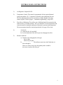
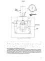
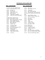
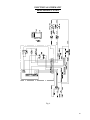
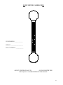
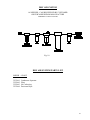
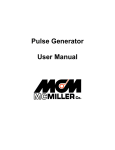
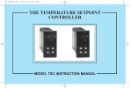
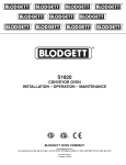
MODEL CS325B ASPHALT ROLLING
THIN FILM OVEN
OPERATING INSTRUCTIONS
1998
JAMES COX AND SONS, INC.
1085 Alpine Way
P.O. Box 674
Colfax, CA 95713
PAGE
Revised February 28, 2002
CONTENTS
2.
Model CS325B
3.
Important Precautions
4.
Getting Started: Electrical and Air Requirements
5.
Operating Instructions
6.
System Checks: 1) Air Regulator
2)
3)
4)
5)
Temperature Control
Flow Meter Calibration
Air Nozzle
Moisture Indicator
7.
Control Panel Layout-Front Fig.1
8.
Control Panel Layout-Back Fig.2
9.
Controller Programming
11.
ASTM Spec D 2872-97
19.
Parts List
20.
Electrical Schematic 60Hz Fig.6
21.
Electrical Schematic 50Hz Fig.7
22.
Motor Control Settings 50Hz Fig.8
23.
Air Schematic Fig.9
24.
Flow Meter Calibration Chart
25.
Dry Air System Schematic Fig.10
26.
Temperature Sensor Modification
27.
Troubleshooting
28.
F.A.Q. ( Frequently Asked Questions )
29.
Calibration
30.
Warranty
1
James Cox & Sons, Inc. 1997
MODEL CS325B ASPHALT ROLLING THIN FILM
OVEN
The Model CS325B Precision oven is designed for the specific requirements of the Asphalt
Rolling Thin Film Tests as specified in State of California Test Method 346-E, AASHO T-240
and ASTM D2872.
Repeatability of the aforementioned test is directly related to the accuracy with which the oven
temperature can be maintained to the specified standard temperature of 325° F (163° C), and the
reproducibility of the thermal rise-time of the system within the time period allocated from load
time to assumed equilibrium of the system. The CS325B has been designed to optimize the
precision of performance with regard to maintenance of setpoint while attaining high-speed
recovery from thermal disturbances caused by reloading.
The oven temperature is sampled by a precision sensor exposed to the supervised environment
at a location which is representative of the desired specimen location. The thermal mass of the
sensor is extremely low, having a thermal/electrical time constant measurable in seconds.
The system is a fully stabilized closed loop thermal/electrical feedback control system. The
system has fast response, tight control limits and freedom from overshoot. There are no
mechanical relays, contactors, commutators, mechanically operated or thermal-pressure magnetic
devices utilized. The entire system is fully electronic, noiseless and non-mechanical in nature.
There is nothing to wear or fatigue. High speed of response is assured by complete control of a
2000 watt heating element. Thermal conduction and radiation losses are low and virtually all
applied power is consumed in replacing losses due to the air vents required for dissipation of
expended volatile from the specimens.
Every precaution has been taken in the preparation of this publication. Cox & sons assumes no
responsibility for errors or omissions. Neither is any liability assumed for damages resulting from
use of the information contained herein.
2
IMPORTANT
1. Do not open door with blower or rack-motor on.
2. Disconnect oven power supply at source when working inside the cabinet to
avoid electrical shock.
3. Turn sample rack with control button to prevent damage to gear reducer.
4.
The air nozzle will cause breakage if the sample containers are not placed
firmly against the rack backstop.
3
ELECTRICAL REQUIREMENTS
Electrical: Maximum load, 2 KVA. Power factor, 0.90.
2000 Watt heating element.
Standard: 208 - 240 VAC, 60 Cycle, single phase. 3 Wire grounded neutral.
Optional: 220 VAC, 50 Cycle, single phase.
Thermal Protection: Electrical circuits fully protected by temperature switch and fuses in
both legs. The thermal protection on the switch is 425° F.
The switch allows the heat to shut down at 425° F and turn
back on at 375° F repeatedly until the problem is resolved.
See page 20, Fig.6, 60Hz or page 21, Fig.7 50Hz for
Electrical Schematic.
AIR REQUIREMENTS
Air System Requirements:
a)
b)
c)
d)
Air supply to this unit should not exceed 125 PSI
Supply dry clean air. See page 25, Fig.10 for example
If air supply is contaminated, install an air filter
If moisture or oil fumes are present, install a dehydrator
4
OPERATING INSTRUCTIONS
Step 1: Push Power Button
Push Power Blower and Sample Rack Buttons.
Step 2: Set air pressure by using pressure regulator knob. Pull Knob out to
release lock. Turn until it reads 50 PSI on pressure gauge. Push knob
to re-lock. Set air flow tube by using flow meter control knob, turning
counter-clockwise. Bring ball up to the calibrated set point.
See page 24.
Step 3: Allow oven to come up to temperature and stabilize at 163° C.
Oven is now ready to install test samples. Turn blower and sample rack
off, leaving power button on. Put bottles in rack, close door and turn
on blower and sample rack. Oven will return to 163° C in 10 minutes.
The test should be performed following the AASHO T-240 and ASTM
D2872 procedures. See page 11 ASTM Specs.
NOTE: Your oven temperature controller has been programmed at our facility to
perform applicable tests. You should not need to change any controller
settings, if you do need to adjust temperature refer to page 9.
5
CONTROL PANEL-SYSTEM CHECKS
1)
Air Regulator: Setpoint 50 PSI.
2)
Temperature Control: The control is programmed for the required thermal
rising time and the 163° C setpoint as required by the rolling thin film test.
The only adjustment that may be necessary is a slight change in the temperature setpoint. Refer to page 9, “Controller Programming”, steps 4 & 5
3)
Flow Meter Calibration: The air flow rate of 4000ml should be measured at the
outlet nozzle by a suitable method. The oven should be at room temperature and
correction made to standard conditions of barometric pressure and temperature.
This measurement should be checked periodically. See page 24 for chart
4)
Air Nozzle:
a) Clean with No. 60 twist drill.
b) Use the shank end of the drill to prevent enlarging the orifice.
5)
Moisture Indicator:
a) Contains color-changing blue silica gel;
•dry air-blue
•moist air-pale pink
b)
The indicator reactivates itself when dry air
flows through it.
However, in time it may lose this quality and it would be
necessary to replace the silica gel.
6
CONTROL PANEL LAYOUT
FRONT
Fig. 1
7
CONTROL PANEL LAYOUT
BACK
Fig. 2
8
CONTROLLER PROGRAMMING
Step 1: To enter into program A.
Push the PAR button once, this puts you into program A.
Step 2: To enter into program 1, 2, or 3.
For instance, you want program 2, you press PAR button four times,
the control will then flash “CNFP” or “NO” on screen. At this point you
need to press the UP button on the controller two times, which puts you
into program 2. If you want to program 3, press the UP button three
times.
Step 3: Programming the 1, 2, or 3.
For instance, if programming is needed to program 2; after entering into
program 2, press the PAR button once, twice, three times, etc., until
required letters appear on the screen. Press the UP or DOWN button to
obtain the correct number needed.
Press the PAR button repeatedly until “CNFP” or “NO” flashes on the
screen. At this point, press the UP or DOWN button to enter in another
program and repeat procedure or press PAR button when “CNFP” or
“NO” is on screen. When the program is complete, “END” will appear
on the screen; the controller will then display “TEMP”.
TEMPERATURE ADJUSTMENT
Step 4: After the oven has been running and temperature is stabilized on
controller, make a comparison to an ASTM thermometer. If there is
a difference, you need to enter program 1. After entering program 1,
press the PAR button six times. SHFE should appear on the screen. At
this time you would press the UP or DOWN button depending on the
oven temperature; UP to cool and DOWN to heat.
Step 5: To end procedure, press the PAR button until “CNFP” or “NO” appears
on the screen. Press PAR once again, “END” will appear and controller
will return to normal display.
9
CONTROL PANEL PROGRAM
A
PROP
Proportional Band
0.5
INTT
Integral Time
70
DERT
Derivative Time
2
(CNFP or NO)
______________________________________________________________________
1
TYPE
Input Sensor Type
R385
SCAL
Temp. Scale Units
°C
DEPE
0.0
FLTR
Digital Filtering
3
SPAN
Input Slope
1.000
SHFT
Input Offset
±
SPLO
Setpoint Lower Limit
50.0
SPHI
Setpoint Upper Limit
200.00
SPRP
Ramp Rate
25
____________________________________________________________________
2
OP
CYCT
OPAC
OPLO
OphI
OpfL
OPDP
Access Output Power
Cycle Time
Control Action
0
Output Lower Upper
Limit Range
Sensor Fail Power
Preset
Output Power Dampening
On/Off Control Hysteresis
Auto Tune Dampening
Code
1
REV
65
0
3
ChyS
1.0
tcod
4
_______________________________________________________________________
3
SP-ENT
OP-ENT
DEV-RED
UDSP-RED
CODE
Access Code Number
0
PID-ENT
TRNF-LOC
Enable Auto/Man Transfer
LOC
TUNE-LOC
Enable Auto-tune
LOC
10
ASTM SPEC D 2872-97
Standard Test Method for
Effect of Heat and Air on a Moving Film of Asphalt
( Rolling Thin-Film Oven Test )
11
Designation: D 2872 - 97
AMERICAN SOCIETY FOR TESTING AND MATERIALS
1 X Barr Harbor Dr. West Conshohocken, PA 19428
Reprinted from the Annual Book of ASTM Standards. Copyright ASTM
Standard Test Method for
Effect of Heat and Air on a Moving Film of Asphalt (Rolling
Thin-Film Oven Test) 1
This standard is issued under the fixed designation D 2872; the number immediately following the designation indicates the year of original
adoption or, in the case of revision, the year of last revision. A number in parentheses indicates the year of last reapproval. A superscript epsilon
(E) indicates an editorial change since the last revision or reapproval.
Scope
1.1 This test method is intended to measure the effect of heat and air on a moving film of
semi-solid asphaltic materials. The effects of this treatment are determined from measurements
of the selected properties of the asphalt before and after the test.
1.2 The values stated in inch-pound units are to be regarded as the standard.
1.3 This standard does not purport to address all of the safety concerns, if any associated with
its use. It is the responsibility of the user of this standard to establish appropriate safety and
health practices and determines the applicability of regulatory limitations prior to use.
2. Referenced Document
2.1 ASTM Standard:
D 113 Test Method for Ductility of Bituminous Materials 2
D 2171 Test Method for Viscosity of Asphalt's by Vacuum Capillary Viscometer 2
E I Specification for ASTM Thermometers 3
3. Summary of Test Method
3.1 A moving film of asphaltic material is heated in an oven for 85 min at 325°F (163°C). The
effects of heat and air are determined from changes in physical test values as measured before
and after the oven treatment. An optional procedure is provided for determining the change in
sample mass.
3.2 Precision values for this test method have been developed for viscosity at 140°F (60°C);
and ductility at 60° (15.6°C).
4. Significance and Use
4.1 This test method indicates approximate change in properties of asphalt during conventional
hot-mixing at about 302°F (150°C) as indicated by viscosity and other rheological measurements.
It yields a residue, which approximates the asphalt condition as incorporated in the pavement. If
the mixing temperature differs appreciably from the 302°F (150°C) level, more or less effect on
properties will occur. This test method also can be used to determine mass change, which is a
measure of asphalt volatility.
5. Apparatus 4
5.1 Oven—This shall be a double-walled electrically heated convection-type oven. Its inside
dimensions shall be 15 in. (381 mm) high, 19 in. (483 mm) wide, and 17-1/2 ± 1/2 in. (445 ± 13
mm) deep (with the door closed). The door shall contain a symmetrically located window with
dimensions of 12 to 13 in. (305 to 330 mm) wide by 8 to 9 in. (203 to 229 mm) high. The
window shall contain two sheets of heat-resistant glass separated by an air space. The window
should permit an unobstructed view of the interior of the oven. The top of the upper heating
element shall be 1 ± 1/8 in. (25 ± 3 mm) below the oven floor.
12
5.1.1 The oven shall be vented at the top and bottom. The bottom vents shall be located
symmetrically to supply incoming air around the heating elements. They shall have an open area
2
of 2.31 ± 0.11 in (15.0 ± 0.7 cm 2 ). The top vents shall be symmetrically arranged in the upper
part of the oven and have an open area of 1.45 ± 0.07 in 2 (9.3 ± 0.45 cm 2 ).
5.1.2 The oven shall have an air plenum covering the sidewalls and ceiling. The air space shall
be 1-1/2 in. (38.1 mm) deep from the walls and ceiling. At a midpoint in the width of the oven,
and 6 in. (152.4 mm) from the face of the circular metal carriage to its axis, a squirrel cage-type
fan 5-1/4 in. (133 mm) OD by 2-7/8 in. (73 mm) wide shall be turned at 1725 rpm by an
externally mounted motor. The squirrel cage fan shall be set so that the fan turns in an opposite
direction to its vanes. The airflow characteristics of the fan-plenum system shall be suction from
the floor of the oven through the wall plenums and exhaust of the air through the fan. Figures 3
and 4 show details of this plenum system.
5.1.3 The oven shall be equipped with a proportional control thermostat capable of maintaining
325°F (163°C) temperature within ±1.0°F (±0.5.C). The sensing element of the thermostat shall
be placed 1 in. (25.4 mm) from the left side and approximately 1-1/2 in. (38.1 mm) from the
ceiling of the interior of the plenum-enclosed oven so that the end of the sensing element is at a
point approximately 8 in. (203.2 mm) from the rear interior wall of the oven. The thermometer
shall be hung or affixed to a mounting in the ceiling which is 2 in. (50.8 mm) from the right side
of the oven at a midpoint in the depth of the oven. The thermometer shall hang down into the
oven so that the bulb of the thermometer is within 1 in. of an imaginary line level with the shaft
of the circular metal carriage. The heating controls shall be capable of bringing the fully loaded
oven back to the test temperature within a 10-min period after insertion of the samples in a
preheated oven.
5.1.4 The oven shall be provided within a 12-in. (304.8mm) diameter, vertical circular carriage
(see Fig. 4 for details). This carriage shall be provided with suitable openings and clips for firmly
holding eight glass containers in a horizontal position (see Fig 5). The vertical carriage shall be
mechanically driven through a 3/4-in. (19-mm) diameter shaft at a speed of 15 ± 0.2 r/min.
5.1.5 The oven shall be equipped with an air jet positioned to blow heated air into each bottle
at its lowest point of travel. The air jet shall have an outlet orifice 0.04 in. (1.016 mm) in
diameter (No. 60 drill) connected to a 25 (7.6-m) length of 5/16 in. (8-mm) outside diameter
refrigeration copper tubing. This tubing shall be coiled to lie flat on the bottom of the oven and
lead to a source of fresh, dried, dust-free regulated air.
5.2 Flowmeter—The flowmeter may be any suitable type capable of accurately measuring the
airflow at a rate of 4000 mL/min. The flowmeter shall be located downstream of all regulating
devices and upstream of the copper coil. The flowmeter shall be positioned so it is maintained at
approximately room temperature. The airflow shall be calibrated periodically using a wet-test
meter or other displacement method. This calibration shall be based on airflow exiting the air jet
and shall be conducted with the oven off and at room temperature.
1This test method is under the jurisdiction of ASTM Committee D-4 on Road and Paving Materials and is the direct responsibility of
Subcommittee D04.46 on Durability and Distillation Tests. Current edition approved April 10, 1997. Published April 1998. Originally
published as D 2872 - 70. Last previous edition D 2872 - 88 ( 1995)ei.
2 Annual Book of ASTM Standards, Vol. 04.03.
3 Annual Book of ASTM Standards, Vol. 14.03.
4 Complete equipment may be obtained from James Cox and Sons Inc., P.O. Box 674, Colfax, CA 95713.
13
D 2872
FIG. 3 Schematic of Air Flow Front View
Note 1—Activated silica gel treated with an indicator is a satisfactory desiccant for the dried air.
5.3 Thermometer—This shall be an ASTM Loss on Heat Thermometer conforming to the
requirements for Thermometer 13C as prescribed in Specification E 1. This thermometer shall be
used to make all temperature measurements required by this test method.
5.4 Container—The container in which the sample is to be tested shall be of heat-resistant
glass conforming to the dimensions shown in Fig 5.
5.5 Cooling Rack—A wire or sheet metal rack constructed of stainless steel or aluminum,
which allows the sample containers to cool in a horizontal position, with each container in the
same horizontal plane. The rack shall be constructed in a way that allows air to flow freely
around each container with at least 1 in. (2.5 cm) clearance between containers and at least 1 in.
(2.5 cm) clearance between the containers and any solid surface.
14
D 2872
Fig. 4 Circular Carriage
FRONT VIEW
MATERIAL—
PYREX BRANO TUBING
STANOARO WALL
64 MM O.D.
WALL THICKNE55
24MM ± 3 MM
SIDE VIEW
6. Preparation of Oven
6.1 Position the air outlet orifice so that it is 1/4 in.
(6.35 mm) from the opening of the glass container. The
orifice shall also be so positioned that the jet blows
horizontally into the central arc of the opening of the
circling glass container.
6.2 Position the thermometer specified in 5.3 so that the
end of the bulb of the thermometer is within 1 in. (25.4
mm) of an imaginary line level with the center of the shaft
holding the revolving carriage.
6.3 Level the oven so that the horizontal axes of the
glass containers when in position in the carriage are level.
6.4 Preheat the oven for a minimum of 16 h prior to
testing with the control thermostat adjusted to the setting
that will be used during the test. This setting shall be
selected such that when the oven is fully loaded and the air
is on, the oven will equilibrate at 325 ± 1°F (163 ± 0.5.C),
as indicated by the test thermometer.
NOTE 2—Because the presence of sample containers affects the temperature
distribution in the oven, containers must be present in the oven when the thermostat
seeing is determined. The use of empty containers is acceptable for this purpose.
SAMPLE BOTTLE
FIG. 5 Sample Bottle
15
D 2872
Test Method
Single-operator precision:
Viscosity at 140°F (60°C)
Ductility at 60°F (15.6°C)A
Multilaboratory precision:
Viscosi1y at 140°F (60°C)
Ductility at 60°F (15.6°C)^
Standard Deviation (1s)
...
3 rrn
..
6 an
Acceptable Range of
Two Results (d2s)
Coefficient of Variation
(Percent of mean)
(1s %)
...
Acceptable Range of Two
Results (percent of mean)
(d2s %)
2.3
9 un
…
...
16 cm
...
6.5
...
4.2
11.9
.. .
A This is based on the analysis of data resulting from tests by 16 laboratories on two asphalt's ranging born 13 to 30 cm.
7. Procedure
7.1 The sample as received shall be free of water. Heat the sample in its container with a loosely
fitted cover in an oven not to exceed 302°F (150°C) for the minimum time necessary to ensure
that the sample is completely fluid. Manually stir the sample but avoid incorporating air bubbles.
7.2 Pour 35 ± 0.5 g of the sample into each of the required glass containers, providing sufficient
material for characterizing tests which are to be run on the residue.
7.3 Immediately after pouring the sample into a glass container, turn the container to a
horizontal position, without rotating or twisting. Place the container in a clean cooling rack,
which is maintained in a draft free, room temperature location, away from ovens or other sources
of heat.
NOTE 3—For maximum precision in determining mass change, the cooling rack should be in a location that is the same temperature and
humidity as the balance used for measuring the mass of the containers.
7.3.1 Allow the glass sample containers to cool in the cooling rack for a minimum of 60 min,
and a maximum of 180 min.
7.3.2 When mass change is being determined, use two separate containers for this
determination. After cooling, separately place each of these containers vertically on an analytical
balance, and determine its mass to the nearest 0.001 g.
7.4 With the oven at operating temperature and the airflow set at 4000 ± 200 mL/min, arrange
the containers holding the asphalt in the carriage so that the carriage is balanced. Fill any unused
spaces in the carriage with empty containers. Close the door and rotate the carriage assembly at a
rate of 15 ± 0.2 r/min. Maintain the samples in the oven and the air flowing and the carriage
rotating for 85 min. The test temperature 325 ± 1°F (163 ± 0.5.C) shall be reached within the first
10 min; otherwise, discontinue the test.
7.5 At the conclusion of the testing period, remove any samples for mass change determination
and place them horizontally in the cooling rack. Then, remove each remaining glass sample
container, one at a time, and transfer its contents to a collection container having a capacity at
least 30 % greater than the total expected volume of residue. This transfer shall be accomplished
by first pouring out any residue that will flow freely from the glass sample container and then
scraping out as much of the remaining residue as practical. While the residue is being removed
from each sample container, the oven door shall remain closed, with the heater power on, the air
16
on, and the remaining samples rotating in the carriage. The final container shall be removed from
the oven within 5 min of removal of the initial container.
NOTE 4—Any scraping tool or technique may be used, as long as an average of 90 % or more of the residue is removed from the sample
containers. It has been determined that circumferential scraping tends to be more effective than lengthwise scraping
7.6 After removing the residue from each of the glass containers, gently stir the collection
container to homogenize the residue without introducing air into it. Test the residue within 72 h
of performing the RTFO test.
7.7 If the mass change is being determined, allow the designated residue sample containers to
cool on the cooling rack for a minimum of 60 min and a maximum of 180 min. After cooling,
place each container vertically on an analytical balance and determine its mass to the nearest
0.001 g. Discard the residue from mass change determination, and do not use it for other tests.
NOTE 5—To improve mass change precision, the containers used for determining mass change should be handled with clean gloves or tongs,
and transfer to the balance should be done with tongs, to prevent temperature changes which could distort the mass measurement.
8. Report
8.1 Report the results from RTFO test in terms of the physical changes in the asphalt brought
about by this method. These values are obtained by performing appropriate ASTM tests on the
asphalt before and after the moving film oven cycle.
8.2 When determined, report the average mass change of the material in the two containers as a
mass percent of the original material. Report this calculated result to the nearest 0.001 %. A mass
loss shall be reported as a negative number while a mass gain shall be reported as a positive
number.
Note 6—This test can result in either a mass loss or a mass gain. During the test, volatile components evaporate, causing a decrease in mass,
while oxygen reacts with the sample, causing an increase in mass. The combined effect determines whether the sample has an overall mass gain
or an overall mass loss Samples with a very low percentage of volatile components usually will exhibit a mass gain, while samples with a high
percentage of volatile components usually will exhibit a mass loss.
17
9. Precision and Bias
9.1 Criteria for judging the acceptability of the viscosity at l 40°F (60° C) and the ductility at 60°F
(15.6°C) test results on the residue after heating are given in Table 1. The values given in Column 2
are the standard deviations that have been found to be appropriate for the materials and conditions
of test described in Column 1. The values given in Column 3 are the limits that should not be exceeded
by the difference between the results of two properly conducted tests. The values given in Column 4
are the coef6~cients of variation that have been found to be appropriate for the materials and
conditions of test described in Column 1. The values given in Column 5 are the limits that should
not be exceeded by the difference between the results of two properly conducted tests expressed as
a percent of their mean.
9.2 The precision of the loss of mass determinations has not been determined.
10. Keywords
10.1 aging; asphalt cement; rolling thin-film oven test (RTFOT)
The American Society for Testing and Materials takes no position respecting the validity of any patent rights asserted in connection with any
item mentioned in this with any standard. Users of this standard are expressly advised that determination of the validity of any such patent
rights, and the risk of infringement of such rights, are entirely their own responsibility.
This standard is subject to revision at any time by the responsible technical committee and must be reviewed every five years and it not revised
either reapproved or withdrawn. Your comments are invited either for revision of this standard or for additional standards and should be
addressed to ASTM Headquarters. Your comments will receive careful consideration at a meeting of the responsible technical committee,
which you may attend. It you feel that your comments have not received a fair hearing you should make your views known to the ASTM
Committee on Standards, 100 Barr Harbor Drive, West Conshohocken, PA 19428
18
CS325B RTF OVEN PARTS LIST
Item #
Item Description
325:01B
325:01A
325:02
325:03
325:04
325:06
325:07
325:08
set)
325:09B
325:09A
325:10
325:11
325:12
325:13
325:14
325:15
325:16
325:17
325:20
325:21
325:26
325:27
325:28
Bodine Rack Motor 60cycle
Dayton Rack Motor 50cycle
Heating Coil
Power Switch
Sample Rack Switch
Blower Switch
Sample Rack Assembly
Sample Rack Spindle Bushing-(1
Blower Motor 60cycle
Blower Motor 50cycle
Blower Motor Flexible Coupling
Blower Spindle Housing
Blower Shaft-3/8 Diameter
Blower Bushings
Squirrel Cage
Top Motor Mount
Air Heating Coil
Flow Meter Adjustment Valve
Moisture Indicator
Air Regulator
Sample Bottles-Clear
Sample Bottles-Frosted
Air Nozzle
Item #
Item Description
325:29
325:30
325:31
325:32
325:33
325:33B
inch)
325:35
325:36
325:37
325:38
325:39
325:40
325:41
325:42
325:44
325:51A
325:51B
325:53
325:54
325:55
325:56
325:57
325:58
Rack Shaft
Rack Fingers-(set of 8)
Transformer
Rack Spindle Housing
Silicon Gasket for Door (per inch)
Silicon Gasket for Door Glass (per
Plastic Handle for Door
Handle Assembly (include. #35)
Silica Gel-1LB can
Pyrex Plate
Thermometer
Chain
Transite Plate
Latch-Set (inside)
DC Motor Control
RTD Sensor
RTD Sensor
Controller-Series B
lst Micro Switch Cvr
Jar Tongs
Drive Gear 25B15 (small 60Hz)
Drive Gear 25B25 (medium 50Hz)
Drive Gear 25B30 (large 60Hz )
19
ELECTRICAL SCHEMATIC
60 Hz ASPHALT OVEN
Fig. 6
20
ELECTRICAL SCHEMATIC
50 Hz ASPHALT OVEN
Fig. 7
21
MOTOR CONTROL
SETTINGS & LOCATION
50 Hz
Fig. 8
22
AIR SCHEMATIC
Fig. 9
23
FLOW METER CALIBRATION
OVEN MODEL# _____________
SERIAL# ___________________
Date of Calibration ____________
ADJUST CENTER OF BALL TO ___________ ON FLOW METER THIS
WILL EQUAL A CALIBRATED FLOW FOR 4000 ML.
24
DRY AIR SYSTEM
AS NEEDED - CAN BE SUPPLIED BY CUSTOMER
OR PURCAHSED FROM MANUFACTURE
FOR PRICE CONTACT SALES
Fig. 10
DRY AIR SYSTEM PARTS LIST
ORDER
#-PART
325:DA1
325:DA2
325:DA3
325:DA4
Condensate Seperator
Filter
Oil Coalescing
Desiccant Dryer
25
CS325 RTF OVEN MODIFICATION
The ASTM Specification requires the Control Temperature Sensor be mounted
1 inch (25.44mm) from the left side and approximately 1.5 inches (38.1mm) from the
ceiling of the interior plenum. The end of the sensing element should be at a point
approximately 8 inches (203.2mm) from the rear interior wall of the oven. The location
of this sensor, as required by the ASTM specification, makes it impossible to control
the temperature in the 10 minute ramp time allowed without over-shooting the required
set point of 163° C (it over-shoots approximately 2° C).
The basic problems are the location of the control sensing element and insufficient
air flow pass the sensor. ASTM requires the temperature is to be measured at mid point
of the oven by a certified thermometer. The control sensor should also be located near the
bulb of the thermometer.
In the original oven design, prior to the addition of the blower system, the control
sensor was placed next to the thermometer in the center of the oven. At that time the
oven conformed to the 10 minute ramp specification without over-shoot.
The temperature controller we now use is a programmable Microprocessor unit with
PID tuning constants, over-shoot suppression, dampening, ramping, etc. Using
this state-of-the-art control with various programs, we still have approximately 2° C
of over-shoot.
We realize this is an ASTM standard test and they require the control sensor at a
specific location. We are furnishing the unit with two control sensors. For the most
precise control and no over-shoot, we use the one located near the bulb of the thermometer and the ASTM sensor with wiring installed but not connected. We are
leaving the choice of which sensor to use up to our customers. If you wish to use the
ASTM location sensor, (with over-shoot), disconnect the power from the oven and
exchange the wiring at the temperature controller terminal block connector numbers
10, 11, and 12.
ASTM sensor color code: Red 10
Red
11
White 12
26
Troubleshooting
In Case of apparent malfunction, please check the following points first.
1. Noisy Rack Motor ?
Check chain for adjustment, the Sprocket on
the Rack may be tight (adjust to .020), or
you may have a bad motor.
2. Noisy Blower Motor ?
Check Graphite Bushings (they may be
worn), Squirrel cage may be out of balance
or it needs to be tightened, Improper
adjustment, Bad Motor.
3. Rack will not Turn ?
Bad Rack Motor, Check fuse, Sprocket is
loose on Motor, Bad Rack Switch
4. Power on, but no Heat ?
Bad RTD Sensor, Bad connections to
heating coils, Check Fuse, Bad Switch,
Check for broken wire from RTD to
Controller.
5. No Power to Oven ?
Check wiring from your service panel to
oven, Check Fuses, See Schematic for your
Oven. See Page 20 Fig.6 or 21 Fig.7 in your
User Manual.
27
F.A.Q.
Frequently Asked Questions
1. Power Requirements ?
See Page 4 in the User Manual.
2. What is the Max. Air Pressure ?
Air supply to this unit should not exceed 125
PSI, See Page 4 in the User Manual.
3. What PSI should I set the Regulator to ?
Turn regulator until Pressure Gauge reads 50
PSI, See Page 4, 5 in the User Manual.
4. Has the Flow Meter been Calibrated ?
Yes, to 4000ml we calibrate before shipping,
See Page 24 in the User Manual.
5. Do we offer On Site Service ?
Yes, Please call (530)346-8322 for On Site
Service Quotation.
6. Can I Mount a Hood Vent to Oven ?
Yes, as long s it doesn't Touch the oven or
interfere with the performance of Oven.
7. Witch RTD should I be using ?
See Page 26 in the User Manual.
28
CALIBRATION
1. Temperature:
Our units are supplied with a digital readout. You need to have an ASTM Loss on
Heat Thermometer positioned in the RTF Oven per ASTM D 2872-97. The thermometer
must reflect the same temperature as the digital readout. The RTD in the digital readout will
have a faster reacting time than the thermometer. Our units are preset at the factory. You
may need to make some fine tuning adjustments as humidity, elevation, and room
temperatures are factors in proper temperature settings.
2. Flow Meter:
We suggest using a Mass Flowmeter for calibration of you flowmeter. You can
purchase these units from Omega at (1-800) 826-6342. We use a Certified Mass Flow Meter
to calibrate our units prior to shipment.
3. Rack Rotation:
Our 60 cycle units are preset from the factory.
Our 50 cycle units use a variable DC Speed Control and the Rpm’s of the Rack and
Blower Motors require calibration on installation. You can purchase an optical tachometer
from the Cole-Parmer Instrument Co. (1-800) 323-4340, catalog no. E-87500-10.
29
WARRANTY
James Cox & Sons, Inc. warrants all manufactured products to be free of mechanical and
electrical defects in materials and workmanship for a period of one year from the date of
acceptance by the purchaser. If the date of acceptance is unduly prolonged, the warranty
period wi11 automatically commence thirty (30) days from the date of delivery at the
customer's site.
James Cox & Sons, Inc. wi11 replace or repair free of charge, but not including
transportation costs, installation or any other service charges, components or assemblies that
are manufactured by us which our inspection reveals to be defective, provided they are
returned to our plant within the warranty period. The warranty extends only to those
products that have been assembled and installed according to our instructions or by a
qualified service engineer. All standard components are covered under the same warranty.
Other non-standard, major items which are not manufactured by us but have been requested
by the customer as an addition to a standard unit will carry the remaining portion of the
warranties of the original manufacturer.
This warranty does not cover normal wear of parts or damage resulting from any of the
following: negligent use or misuse of the product, use on improper voltage or current, use
contrary to operating instructions, or disassembly, repair or alteration by any person other
than an authorized service engineer.
The terms of the warranty are revoked if any part or assembly is physically modified in any
manner whatsoever by the customer or agency other than James Cox & Sons, Inc. without
written permission.
Assistance agreements are available for products that require on-site repair. The agreements
provide emergency service when deemed necessary by the customer. Tourist-class round trip
airline transportation wi11 be charged at cost, along with current daily rates for field service
personnel.
30