1
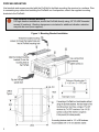
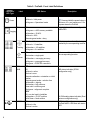
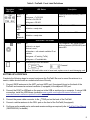
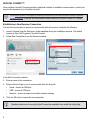
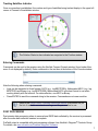
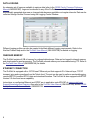
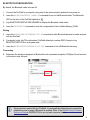
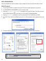
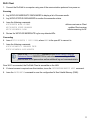
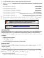
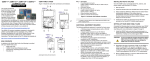
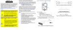
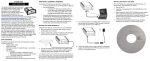
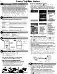
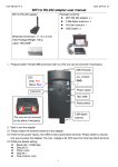
ProPak6™ QUICK START GUIDE GM-14915125 Rev 1 August 2013 ProPak6 - Front This guide provides the basic information needed to set up and use a NovAtel® ProPak6. USER MANUALS For detailed information on the installation and operation of the NovAtel receiver, download the ProPak6 User Manual (OM-20000148). For detailed information on the logs and commands used to configure the NovAtel receiver, download the OEM6 Family Firmware Reference Manual (OM-20000129). Both manuals are available from: www.novatel.com/support/firmware-software-and-manuals/productmanuals-and-doc-updates/oem6-family. BOX CONTENTS The following is provided with the ProPak6 (NovAtel part number): • • • • • • ProPak6 receiver with built in Wi-Fi, Bluetooth®, USB 2.0 and 4 GB of onboard memory 12 VDC power adapter (CLA) with slow blow fuse (01017663) Null modem serial cable (01017658) DB9 male extension cable (01018520) I/O DB9 male interface cable (01018519) Mounting bracket and screws (70023096, quantity 2 and 28523058, quantity 4) Additional Equipment Required The additional equipment listed below is required for a typical setup (refer to ProPak6 User Manual (OM20000148) for further details). • A standard 12 VDC power outlet or 9-36 VDC power supply capable of at least 14 W • A Windows computer with a RS-232 DB-9, Ethernet or USB port • A quality GNSS antenna, such as NovAtel’s 700 or ANT series • An antenna cable with a TNC male connector at the receiver end such as NovAtel’s GPS-C016 model • A cellular antenna and SIM card (model dependant) ProPak6 - Back 1 PROPAK6 MOUNTING Use brackets and screws provided with the ProPak6 to facilitate mounting the receiver to a surface. Prior to connecting any cables and installing the ProPak6 in a fixed position, attach the supplied mounting brackets to the ProPak6. High Vibration ProPak6 Mounting For high vibration installations, mount the ProPak6 directly using 1/4” 20-UNC threaded screws (4 locations). Vibration dampeners or isolators for additional vibration reduction may also be used (user supplied). Figure 1: Mounting Bracket Installation 2 GETTING TO KNOW THE PROPAK6 Refer to ProPak6 User Manual (OM-20000148) for details on all ProPak6 connectors, labelling and LEDs as well as detailed installation and operation instructions. Refer to the OEM6 Firmware Reference Manual - OM-20000129 for details regarding any ProPak6 logs or commands. Table 1: ProPak6 - Back Connector Definitions Connector Type GNSS Antenna Connector Label ANT 1 GNSS GPS1 and GPS2 antennas (TNC) (model dependant) ANT 2 or or GNSS GPS1 antenna (TNC) and external oscillator (BNC) (model dependant) ANT1 External Oscillator Description OSC 4-pin LEMO power connector Power PWR EXP. 9-pin LEMO expansion port for CAN1 and CAN2 Expansion USB DEVICE USB Device (Type micro B) connector (high speed only) 480 Mbps Ethernet RJ45 connector Ethernet I/O 4 Event Input/3 Event Output (DB9 female connector) I/O port is configurable I/O COM1 COM1, COM2, COM3/IMU DB9 male communications port COM2 RS-232 (RS-422 selectable via software) COM3/IMU Serial Communication Ports 3 Table 2: ProPak6 - Front Label Definitions Button/ Connector/ LED Type Label N/A Power LED States Off Power button and status LED Solid red = Valid power Press and hold the power button a Solid green = Operational mode N/A Off Solid green = >40% memory available Logging Description minimum of 3 s and maximum of 10 s to power down the ProPak6 Logging button with user configurable status LED Solid amber = 20-40% Solid red = <20% Alternate green/amber = busy Off = 0 satellites Solid red = 1-3 satellites Tracking Indicates number of satellites being tracked by the corresponding receiver Solid amber = 4-5 satellites Solid green = 6+ satellites Off = no fix Blink amber = single point Position Indicates satellite position status for the corresponding receiver Solid amber = converging accuracy Solid green = converged accuracy Blink green = PSR/PDP corrections INS INS ALN Off Solid red = active Blink red = error Alternate red/amber = orientation or initial position Alternate green/amber = solution free Solid amber = aligning Blink amber = high variance Green solid = solution good Blink green = alignment complete INS status indication (SPAN configuration only) ALN Off = no dual card/<4 satellites Solid amber = FLOAT solution Solid Green = fixed solution HOST Off Solid red = idle Blink red = active 4 ALIGN heading status indication (Dual antenna configuration only) USB Host (Type A) connector ProPak6 built in USB Host with status LED Table 2: ProPak6 - Front Label Definitions Button/ Connector/ LED Type Label LED States COM 1, 2 Off and 3 Blink green = Tx RS-232 Description Transmit/Receive indication (COM 1, 2 and/or 3) Blink red = Rx RS-232 Solid green = RS-422 Off Wi-Fi Wi-Fi radio status LED Solid blue = ready state Off Bluetooth Bluetooth radio status LED Solid blue = ready state CELLULAR - OPTIONAL CELL Off Fully integrated TNC cellular modem antenna connector (GPRS/HSPA) and status LED Solid red = no signal Blink red = error Solid amber = cell network available-IP not available Blink green = IP activity (Tx/Rx) Solid green = IP available/idle SIM Push-push style SIM card holder Open Covered Remove SIM card holder cover to insert card; replace cover to avoid damaging card. SETTING UP A PROPAK6 Complete the following steps to connect and power the ProPak6. Be sure to mount the antenna to a secure, stable structure with an unobstructed view of the sky. 1. Connect GNSS antennas to the ANT1 port and ANT2 port (if equipped) found on the back of the ProPak6 and connect an external oscillator (if equipped) to the adjacent OSC port. 2. Connect the COM1 or USB port on the receiver to the USB or serial port on a computer. If using a USB connection, install the USB drivers (available www.novatel.com/support/firmware-software-andmanuals/firmware-software-updates/novatel-connect/). 3. Connect the power cable connector to the PWR port on the back of the ProPak6. 4. Connect a cellular antenna to the CELL port on the front of the ProPak6 (if equipped). 5. Configure and/or enable ports, radios and receiver settings as required (refer to ProPak6 User Manual (OM-20000148) for details). 5 NOVATEL CONNECT™ Once installed, NovAtel Connect provides a graphical interface to establish communication, control and monitor the operation of your NovAtel receiver. Go to www.novatel.com/support/firmware-software-and-manuals/firmware-software-updates/ novatel-connect/ to access and download the latest version of NovAtel Connect PC Utilities. Establishing a New Receiver Connection The first time a serial port is opened to communicate with the receiver, complete the following: 1. Launch Connect from the Start menu folder specified during the installation process. The default location is Start | All Programs | NovAtel Connect. 2. Select New Connection from the Welcome window. In the New Connection window: 3. Enter a name for the connection. 4. Select a Device Type to use to communicate from the drop list: • • • Serial - choose a COM port USB - choose a COM port Network - choose a receiver and define network settings 5. Click the OK button to save the new connection. 6 Detailed instructions for using NovAtel Connect are available from within the utility Help. Tracking Satellites Indicator Once a connection is established, the number and type of satellites being tracked display in the upper left corner of Connect’s Constellation window. The Solution Status is also indicated as computed in the Position window. Entering Commands Commands can be sent to the receiver using the NovAtel Connect Console window (found under View menu if not displayed by default). Enter commands in the text box at the bottom of the Console window. Note the following when entering commands: • Logs can be requested in three formats: ASCII (e.g., log BESTPOSA), Abbreviated ASCII (e.g., log BESTPOS) and Binary (e.g., log BESTPOSB). Abbreviated ASCII is the best format to use when working directly with the receiver. For data collection, use ASCII or Binary. • Press ENTER to send the command string to the receiver. Commands are not case sensitive. Refer to the OEM6 Family Firmware Reference Manual (OM-20000129) for the list of available commands and logs and the parameters to use. POST PROCESSING Post-mission data processing refers to cases where GNSS data collected by the receiver is processed after the entire data collection session is complete. ProPak6 output is compatible with post-processing software from NovAtel’s Waypoint® Products Group. For details, see www.novatel.com/Products/Waypoint Software. 7 DATA LOGGING An extensive set of logs are available to capture data (refer to the OEM6 Family Firmware Reference Manual-OM20000129). Logs can be directed to any of the ProPak6 communication ports and can be automatically generated when new or changed data becomes available or at regular intervals. Data can be collected through NovAtel Connect using the Logging Control Window. Different logging profiles can also be created to facilitate different logging requirements. Refer to the NovAtel Connect help and/or the ProPak6 User Manual (OM-20000148) for details on logging. ONBOARD MEMORY The ProPak6 contains 4 GB of memory for onboard data storage. Data can be logged to internal memory and downloaded for post-processing. The ProPak6 onboard memory can be accessed using FTP. Refer to the ProPak6 User Manual (OM-20000148) for details. ETHERNET CONNECTION The ProPak6 is equipped with a 10/100 baseT Ethernet port that supports IPv4 Internet layer, TCP/IP transport, ping and connections from the Telnet client. The port can be used to perform remote debugging, receive MRTCA (modified RTCA) data and download firmware. The ProPak6 is also equipped with NTRIP Version 2.0 client and server capability. Instructions on configuring Ethernet and NTRIP are in application note APN-057 at www.novatel.com/ Support/Knowledge and Learning. Also refer to the ProPak6 User Manual (OM-20000148) and the OEM6 Family Firmware Reference Manual-OM20000129. 8 BLUETOOTH CONFIGURATION By default, the Bluetooth radio is turned off. 1. Connect the ProPak6 to a computer using one of the communication ports and turn power on. 2. Issue the BLUETOOTHCONFIG POWER ON command to turn on the Bluetooth radio. The Bluetooth LED on the front of the ProPak6 lights blue . 3. Log BLUETOOTHSTATUS ONCHANGED to display the Bluetooth radio status. 4. Issue the SAVECONFIG command to save the configuration to Non-Volatile Memory (NVM). Pairing 5. Issue the BLUETOOTHDISCOVERABILITY ON command to allow Bluetooth devices to locate and pair with the ProPak6. 6. If prompted, enter the PIN confirmation (ProPak6 default pin number 0000). Accept or log BLUETOOTHSTATUS to verify pass code. 7. Issue the BLUETOOTHDISCOVERABILITY OFF command to turn off Bluetooth discovery. Connecting 8. Determine the serial port assigned to Bluetooth for the connected computer (COM port X) and connect to the device over this port. Once a device is paired with the ProPak6, it is automatically detected and a connection established once in range if Bluetooth is enabled. Refer to the OEM6 Family Firmware Reference Manual-OM20000129 for any log and command details. 9 WI-FI CONFIGURATION When the ProPak6 Wi-Fi radio is enabled, it can be configured to act as a Access Point (AP) or Client. Wi-Fi AP (default) 1. Connect the ProPak6 to a computer using one of the communication ports and turn power on. 2. Log WIFIAPSTATUS ONCHANGED to view connection status. 3. Issue the WIFICONFIG STATE ENABLED command to turn on the Wi-Fi radio. The LED on the front of the ProPak6 lights blue (it may take up to 10 s for the AP to become available). 4. Issue the SAVECONFIG command to save the configuration to Non-Volatile Memory (NVM). 5. On a Wi-Fi Client, scan for a ProPak6 and connect to it. When prompted, enter a password and press OK: 6. Configure network properties on the connected Client computer to use a static IP address. 10 Refer to the OEM6 Family Firmware Reference Manual-OM20000129 for log and command details. Wi-Fi Client 1. Connect the ProPak6 to a computer using one of the communication ports and turn power on. Scanning 2. Log WIFICLISCANRESULTS ONCHANGED to display a list of the scan results. 3. Log WIFICLISTATUS ONCHANGED to monitor the connection status. 4. Issue the following commands: WIFICONFIG MODE CLIENT WIFICONFIG STATE ENABLED WIFICLICONTROL SCAN defines receivers as Client enables Client receiver initiates scanning for AP 5. Review the WIFICLISCANRESULTS log for any detected APs. Connecting 6. Issue WIFICLICONFIG 1 SSID XXXX, where XXXX is the open AP to connect to. 7. Issue the following commands: WIFICLICONFIG 1 ENABLED TRUE WIFICLICONTROL APPLYCONFIG Refer to the WIFICLICONFIG command in the OEM6 Family Firmware Reference Manual-OM20000129 for instructions on connecting to WPA personal and WPA2 personal as well as additional log and command details. Once Wi-Fi is connected, the ProPak6 Client is accessible on the LAN. 8. If internet access is required over this interface, issue the SETPREFERREDNETIF WIFI command. 9. Issue the SAVECONFIG command to save the configuration to Non-Volatile Memory (NVM). 11 CELLULAR NETWORK CONFIGURATION 1. Obtain an active account and SIM card providing GSM/GPRS/HSDPA data services (recommended data plans for Network RTK are 5GB/Month Rate Plans). The Service Provider may require the following information to setup an active account. a. Product Name: ProPak6 GSM/GPRS/HSDPA b. Modem Serial Number (IMEI): Modem serial number from ProPak6 product label Example: The cellular provider may require additional activation steps. Refer to any instructions provided with the SIM card. 3. Remove the SIM card cover, insert the SIM card and replace the cover. Once the SIM card is correctly installed, secure the SIM cover to the base using a screwdriver. Screws should be torqued to 4-6 inch-pound. Failure to properly secure SIM cover will violate ProPak6 IP67 ingress rating. 4. Ensure a cellular antenna is connected to the ProPak6 and turn the ProPak6 power on. 5. Log CELLULARSTATUS ONCHANGED to display the modem and cellular connection status. 12 6. Log CELLULARINFO ONCE to display modem and network information. 7. The CELLULARCONFIG command is issued to configure cellular parameters. The following commands are issued: enables the radio CELLULARCONFIG POWER ON sets AP name1 CELLULARCONFIG APN <APN> CELLULARCONFIG USERNAME <USERNAME> sets user name1 CELLULARCONFIG PASSWORD <PASSWORD> sets APN password1 CELLULARCONFIG DATA ON CELLULARCONFIG DATAROAM ON enables/disables data connectivity on the configured APN enables/disables data connectivity when roaming 8. If internet access is required over this interface, issue the SETPREFERREDNETIF CELL command. 9. Issue the SAVECONFIG command to save the configuration to Non-Volatile Memory (NVM). Cellular data consumption and service charges are dependent on the configuration of the ProPak6 receiver and data logging rates. Refer to the OEM6 Family Firmware Reference Manual-OM20000129 for log and command details. AIRPLANE MODE Enabling Airplane Mode turns off any Wi-Fi, Bluetooth or cellular radios in the ProPak6. Airplane Mode is disabled by default (radio on). If Airplane mode is enabled and then disabled, all radios automatically return to their last state (on or off) however, any connections made before airplane mode was enabled are not restored. • • Issue the following commands: AIRPLANEMODE ENABLE AIRPLANEMODE DISABLE Log AIRPLANEMODE to view the status of Airplane mode. ENABLING SBAS The ProPak6 is capable of SBAS positioning. This positioning mode is enabled using the SBASCONTROL command, as follows: SBASCONTROL ENABLE AUTO Once enabled, the Solution type field shown in the Position window of NovAtel Connect should change from Single to SBAS. SBAS satellites display in the Constellation window. The ProPak6 tracks available SBAS satellites, including WAAS, EGNOS and other SBAS systems. 1.Optional—consult the cellular data provider to determine if required. 13 ENABLING L-BAND L-Band equipped receivers allow sub-metre accuracy. To use this positioning mode, first obtain a subscription to track the OmniSTAR L-Band signal. Various OmniSTAR services are available, for example, VBS, XP, HP and G2. To obtain a subscription, contact OmniSTAR as outlined on their Web site at www.omnistar.com. Before contacting OmniSTAR, have the OSN (OmniSTAR Serial Number, available using the LBANDINFO log) and manufacturer name (NovAtel) ready. The ASSIGNLBAND command allows OmniSTAR base station communication parameters to be setup. It should include a relevant frequency and data rate. The frequency assignment can be made in Hz or kHz. For example: Hz: assignlband omnistar 1536782000 1200 kHz: assignlband omnistar 1536782 1200 A value entered in Hz is rounded to the nearest 500 Hz. To confirm tracking an L-Band signal, log the L-Band status information by entering: log LBANDSTAT. If receiving OmniSTAR HP, the fifth field of the LBANDSTAT log should be 00c2, as shown in the following example: LBANDSTAT COM1 0 81.0 FINESTEERING 1596 235136.000 00000000 d1c2 5968 <1557854678 48.98 1098.9 0.00 00c2 0000 153860 545 0 0000 0201 154019 68000000 00000000 To specify the correction source, use the PSRDIFFSOURCE command as shown in the following example: PSRDIFFSOURCE OMNISTAR otherwise it is left at the default AUTOMATIC 14 Refer to the OEM6 Family Firmware Reference Manual (OM-20000129) for the list of available commands and logs and the parameters used. LOG REAL-TIME KINEMATIC (RTK) POSITIONING Corrections can be transmitted from a base station to a rover station to improve position accuracy to centimetre level. The base station is the GNSS receiver that is acting as the stationary reference. It has a known position and transmits correction messages to the rover station. The rover station is the GNSS receiver that does not know its exact position but which can receive correction messages from a base station to calculate differential GNSS positions. In most cases, a data link between the base station and rover station (two NovAtel receivers) is required in order to receive corrections. It is also possible to receive and use RTK corrections from established networks. SBAS and L-Band corrections can be acquired with one receiver and are exceptions to the base/rover concept, although neither are considered RTK positioning. Generally a link capable of data throughput at a rate of 19200 bits per second, and less than 4.0 s latency, is recommended. Once the base and rover are set up, configure them for RTCA, RTCM, RTCMV3, CMR+, CMR or NOVATELX corrections. Below is a NOVATELX example (replace the latitude, longitude and height coordinates shown with those of the base): Base serialconfig com2 115200 n 8 1 n on fix position [latitude] [longitude] [height] generatertkcorrections novatelx com2 (enter your own lat, long and hgt values) Rover serialconfig com2 115200 n 8 1 n on interfacemode com2 novatelx none off RT-2® with AdVance® RTK, are real-time kinematic software products developed by NovAtel. Optimal RTK performance is achieved when both the base and rovers are NovAtel products; however, AdVance RTK will operate with equipment from other manufacturers when using RTCM, RTCMV3 and CMR messaging. For more base/rover configurations, go to www.novatel.com/support/welcometo-novatel-support and Search Known Solutions for key words “rover base”. Refer to ProPak6 User Manual (OM-20000148) for additional information. SECURITY By default, minimal network/port security is set. It is the responsibility of the user to assess security requirements and configure the ProPak6 as necessary. Refer to the security section of the ProPak6 User Manual (OM-20000148) for security settings. Additional Functionality Refer to the ProPak6 User Manual (OM-20000148) for set up and installation instructions for CAN, External Oscillator and other functionality. 15 CONTACT SALES For product information, contact: novatel.com [email protected] 1-800-NOVATEL (U.S. and Canada) or 403-295-4900 China 0086-21-54452990-8011 Europe 44-1993-848-736 SE Asia and Australia 61-400-883-601 QUESTIONS OR COMMENTS For questions or comments regarding the ProPak6, please contact NovAtel using one of these methods: Email: [email protected] Web: www.novatel.com Phone: 1-800-NOVATEL (U.S. & Canada) 403-295-4500 (International) Fax: 403-295-4501 Quick Start Guide - ProPak6 OEM6, Waypoint, AdVance, NovAtel and RT-2 are registered trademarks of NovAtel Inc. ProPak6 and NovAtel Connect are trademarks of NovAtel Inc. All other brand names are trademarks of their respective holders. © Copyright 2013 NovAtel Inc. All rights reserved. Printed in Canada on recycled paper. Recyclable. Unpublished rights reserved under international copyright laws. 16