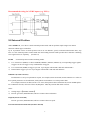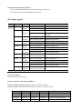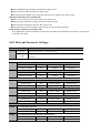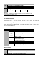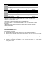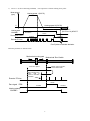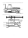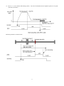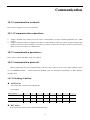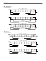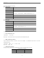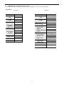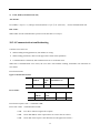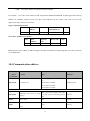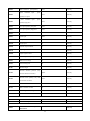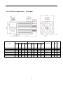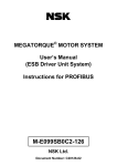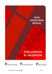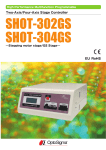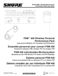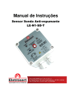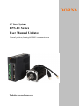
1
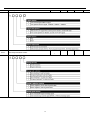
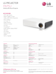
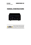
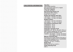
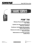
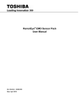
DORNA AC Servo Systems EPS-B1 Series User Manual Updates Internal position, homing & RS485 communnication Website: en.cn-dorna.com 1 Recommended wiring for 24VDC inputs (e.g. PLCs): 8.8 Internal Position When PA000.1=A, servo drive is under internal position mode and can perform simple single-axis motion functions without upper controllers. Up to 16 positions can be set. Each position can set its own distance, speed, acceleration/deceleration time, stop time etc. This internal position control mode also has homing function. Both speeds before and after contacting Zero signal can be set separately. (See PA771) PA700: 1) set internal position control switching modes Use external I/O (PTRG) to choose INPOS0, INPOS1, INPOS2, INPOS3 by corresponding trigger signals. Triggers can be one trigger or any combinations of triggers. 2) Use external I/O (PTRG) to trigger cycle run. Cycle begins with PA700.2 and ends with PA700.3. 3) Internal timer trigger cycle run. Cycle begins with PA700.2 and ends with PA700.3. ■ Distance (PA701 to PA732) Each distance is set by two parameters in pairs, for example, PA701 & PA702, PA703 & PA704 etc. Values in these paired parameters are hexadecimal, with symbols and combine to a 32-bit position data. For example, PA702 is 0x 0007, PA701 is 0x A120, then position data is 0x0007A120, means 500000 pulses. For a 5000-line encoder, each turn creates 20,000 pulses. Thus the position data means 25 turns. Notes: 1) Setting range is【0x0000, 0xFFFF】 2) Electric gear ratio (PA205/PA206) will have counter-effect on distance. ■ Speed (PA733 to PA748) Electric gear ratio (PA205/PA206) will have counter-effect on speed. ■ Acceleration/deceleration time (PA749 to PA764) 2 ■ Stop time at each position (PA765) Only available when PA700.0=2. (Internal timer trigger cycle run) This means time between CMD_OK and next action. 8.8.1 Input signals Type Name Pin Setting Definition Input Signal ZPS To be assigned ON=L electrical level External Zero signal ON (valid) OFF=H electrical level External Zero signal OFF (invalid) To be assigned ON=L electrical level Internal position control stops (valid) OFF=H electrical level Internal position control not stops (invalid) To be assigned ON=L electrical level INPOS0 signal valid OFF=H electrical level INPOS0 signal invalid To be assigned ON=L electrical level INPOS1 signal valid OFF=H electrical level INPOS1 signal invalid To be assigned ON=L electrical level INPOS2 signal valid OFF=H electrical level INPOS2 signal invalid To be assigned ON=L electrical level INPOS3 signal valid OFF=H electrical level INPOS3 signal invalid PTRG To be assigned OFF (H electrical level) to ON (L electrical level) PTRG signal valid P-POS To be assigned ON=L electrical level P-POS signal valid OFF=H electrical level P-POS signal invalid To be assigned ON=L electrical level N-POS signal valid OFF=H electrical level N-POS signal invalid To be assigned OFF (H electrical level) to ON (L electrical level) SHOME signal valid PZERO INPOS0 INPOS1 INPOS2 INPOS3 N-POS SHOME Refer to 3.4.3 for assigning pins. ■ Zero signal (ZPS) Used for homing functions only. ■ Internal position control stops (PZERO) ■ Internal position selection (INPOS0, INPOS1, INPOS2, INPOS3) INPOS0, INPOS1, INPOS2, INPOS3 combines to achieve 16-position control INPOS3 INPOS2 INPOS1 INPOS0 Position number 0 (invalid) 0 (invalid) 0 (invalid) 0 (invalid) Position 0 (PA702&PA701) 0 (invalid) 0 (invalid) 0 (invalid) 1 (valid) Position 1 (PA704&PA703) 0 (invalid) 0 (invalid) 1 (valid) 0 (invalid) Position 2 (PA706&PA705) 0 (invalid) 0 (invalid) 1 (valid) 1 (valid) Position 3 (PA708&PA707) 3 0 (valid) 1 (valid) 0 (invalid) 0 (invalid) Position 4 (PA710&PA709) 0 (valid) 1 (valid) 0 (invalid) 1 (valid) Position 5 (PA712&PA711) 0 (valid) 1 (valid) 1 (valid) 0 (invalid) Position 6 (PA714&PA713) 0 (valid) 1 (valid) 1 (valid) 1 (valid) Position 7 (PA716&PA715) 1 (valid) 0 (invalid) 0 (invalid) 0 (invalid) Position 8 (PA718&PA717) 1 (valid) 0 (invalid) 0 (invalid) 1 (valid) Position 9 (PA720&PA719) 1 (valid) 0 (invalid) 1 (valid) 0 (invalid) Position 10 (PA722&PA721) 1 (valid) 0 (invalid) 1 (valid) 1 (valid) Position 11 (PA724&PA723) 1 (valid) 1 (valid) 0 (invalid) 0 (invalid) Position 12 (PA726&PA725) 1 (valid) 1 (valid) 0 (invalid) 1 (valid) Position 13 (PA728&PA727) 1 (valid) 1 (valid) 1 (valid) 0 (invalid) Position 14 (PA730&PA729) 1 (valid) 1 (valid) 1 (valid) 1 (valid) Position 15 (PA732&PA731) ■ Trigger signal (PTRG) ■ Forward JOG under internal position mode (P-POS) ■ Reverse JOG under internal position mode (N-POS) ■ Homing activiation signal (SHOME) 8.8.2 Output Signals Type Name Pin Status Definition Output Signal HOME To be assigned Active Homing achieved Inactive Homing not achieved Active Position command achieved Inactive Position command not achieved Active Positioning command executed Inactive Positioning command not executed CMD-OK MC-OK To be assigned To be assigned All above output signals need to be assigned according to 3.4.3 ■Important: All above signals are only active under internal positioning mode. ■ Homing (HOME) When homing is achieved and positioning coordinate system is workable, this signal is ON. At powered on, this signal is OFF. When reaching next position, this signal is OFF. 4 When SHOME triggers homing command, this signal is OFF. When homing is achieved again, this signal is ON. Through inputting SZERO (stop command), homing can be stopped, this signal is OFF. ■Position command achieved (CMD-OK) When enter internal position control mode, this signal is ON. When position command is being processed, this signal is OFF. When position command is achieved, this signal is ON. This signal only means command is achieved, not the actual motor positioning. ■ Positioning command executed (MC-OK) This signal means position command execution achieved. When both CMD-OK and COIN are on, this signal is ON, otherwise OFF. 8.8.3 Relevant Parameter Settings Parameter PA000 Meaning h.□□A□ h.□□B□ Internal position control (junction instruction) Internal position control (junction instruction) ←→Position control (pulse instruction) PA701 PA702 Internal Position 0 low-place Setting Scope Unit Factory Setting Effective time 0x0000~0xFFFF pulse 0x4E20 immediate Internal Position 0 high-place Setting Scope Unit Factory Setting Effective time 0x0000~0xFFFF pulse 0x0000 immediate ~~ PA731 PA732 PA733 Internal Position 15 low-place Setting Scope Unit Factory Setting Effective time 0x0000~0xFFFF pulse 0x7100 immediate Internal Position 15 high-place Setting Scope Unit Factory Setting Effective time 0x0000~0xFFFF pulse 0x0002 immediate Setting Scope Unit Factory Setting Effective time 0~5000 rpm 100 immediate Internal position speed 0 ~~ PA748 PA749 Internal position speed 15 Setting Scope Unit Factory Setting Effective time 0~5000 rpm 700 immediate Internal position 0 acceleration/deceleration time Setting Scope Unit Factory Setting Effective time 0~500 mms 0 immediate 5 ~~ PA764 PA765 Internal position 15 acceleration/deceleration time Setting Scope Unit Factory Setting Effective time 0~500 mms 0 immediate Setting Scope Unit Factory Setting Effective time 0~65535 mms 100 immediate Internal position stop time ■Important When PA733~PA748 settings exceed highest speed of the servo motor, actual value is still restricted as servo motor’s highest speed. 8.9 Homing function Normally there should be a zero switch on working tables and is used to determine Zero positions for point-to-point controls. Homing is needed when power-on or after each processing for next movement. In internal position control mode, upper controller gives Homing-Startup (SHOME) signals and the servo driver executes homing functions automatically. Homing modes, homing speeds and deviations can all be set through PA771, PA775, PA776, PA777, and PA778. ■Homing Modes selection Parameter PA771 Meaning d.□□□0 CCW homing d.□□□1 CW homing d.□□0□ Once contact with homing switch, for Z Pulse d.□□1□ Once contact with homing switch, and look for Z Pulse d.□□2□ Once contact with homing switch, move backwards and use departure point as zero point. d.□□3□ Once contact with homing switch, not move backwards, and use departure point as zero point. d.□0□□ Homing achieved, not clear all data d.□1□□ Homing achieved, clear all position data d.0□□□ Use external zero position signal (ZPS) d.1□□□ reserved move backwards and look not move backwards, ■Relevant parameters PA771 PA775 Homing Modes selection Setting Scope Unit Factory Setting Effective time 0x0000~0x1131 ―― 0000 immediate Homing speed 1 (speed before contacting Zero position) 6 PA776 PA777 PA778 Setting Scope Unit Factory Setting Effective time 0~3000 rpm 1000 immediate Homing speed 2 (speed before contacting Zero position) Setting Scope Unit Factory Setting Effective time 0~500 rpm 30 immediate Zero position deviation low 16 place Setting Scope Unit Factory Setting Effective time 0x0000~0x1000 pulse 0 immediate Zero position deviation high 16 place Setting Scope Unit Factory Setting Effective time 0x0000~0xFFFF pulse 0 immediate ■Important 1, When PA775, PA776 settings exceed highest speed of the servo motor, actual value is still restricted as servo motor’s highest speed. 2, Zero position deviation directions are determined by homing directions. Zero position deviation = (Zero position deviation high 16 place <<16) & Zero position deviation low 16 place. 3, Homing functions are suitable for Internal position control (junction instruction) and Position control (pulse instruction). 4, During homing, servo driver does not receive pulse commands. ■Description of the homing process In internal position control mode: When SHOME is detected, motor runs at direction set by PA771.0 and speed set by PA772. When zero position signal ZPS (reference point) is detected active, motor runs at speed set by PA775 after finding Z pulse according to PA771.1 settings. When ZPS is inactive, also after detected Z pulse, motor runs at speed set by PA776 and starts counting zero position deviation pulse numbers. Motor stops and outputs HOME signal. Normally set PA775 at high speed and PA776 at low speed. Note that if PA776 is set too high, homing accuracy will be affected. 7 1) PA771.1=0, after contacting with ZPS, Motor speed (rpm) time sequences of motor looking for Z pulse: Homing speed 1 (PA775) 0 Homing start (SHOME) Zero signal(ZPS) Homing speed 2 (PA776) Deviation = (PA778<<16) & PA777 Esca latio n Active Inactive Inactive Encoder Z Pulse First Z pulse to calculate deviation Relevant positions are shown below: Mechanical moving part Mechanical Zero Swtich Motor S p e e d d o w n, move b ackwards Loo k fo r Z pulse Afte r lea vin g zero poin t, first Z pulse to calculate deviation Encoder Z Pulse Acti ve Zero signal(ZPS) Homing startup (SHOME) Inactive Inactive Rise 8 2) PA771.1=1, after contacting with ZPS, time sequences of motor not return and looking for Z pulse: Homing1 (PA775) Motor speed (rpm) Homing2 (PA776) 0 Homing start (SHOME) Deviation= (PA778<<16) & PA777 Rise Zero signal(ZPS) Valid Inva lid Inva lid Encoder Z pulse First Z pulse to calculate deviation distance after ZPS invalid Relevant positions are shown below: s Mechanical moving part Mechanical Zero swtich Mechanical part moving forward. Not looking for Z Pulse Afte r lea ving Zero switch , first Z pulse to calculate deviation. Moto r speed down Not . moving backwar ds. Encoder Z Pulse Valid Zero Signal(ZPS) Inva lid Inva lid Homing start( SHOME) Rise 9 3) PA771.1=2, Once contact with homing switch, (not look for Z Pulse) : Motor speed (rpm) move backwards and use departure point as zero point Homing1 (PA775) Homing2 (PA776) 0 Deviation= (PA778<<16) & PA777 SHOME Rise ZPS Valid Inva lid invalid Start calculate deviation Relevant positions are shown below: 10 4) PA771.1=3, once contact with homing switch, (not look for Z Pulse) not move backwards and use departure point as zero point Relevant positions are shown below: 11 Communication 10.1 Communication terminals Please refer to chapter 3.3 for CN1 connections. 10.1.1 Communication connections 1) 2) If upper controller only connects to one servo drive, connect RJ45(1) to upper controller and RJ45 (2) to a 120Ω resistor. If upper controller connects to multiple servo drives, connect RJ45(1) of first servo drive to upper controller and RJ45(2) of first servo drive to RJ45(1) of second servo drive. Connect all servo drives in this way and connect RJ45 (2) of last servo drive to a 120Ω resistor. 10.2 Communication parameters Please refer to PA015 and PA016 of the user manual. 10.3 Communication protocols When using RS-485 for serial communications, each servo drive must set its own axis number (PA015). There are two MODBUS modes: ASCII (American Standard Code for information interchange) or RTU (Remote Terminal Unit). 10.3.1 Encoding definition ASCII mode: Every 8-bits date consists of two ASCII bytes. For example: Byte symbol ‘0’ ‘1’ ‘2’ ‘3’ ‘4’ ‘5’ ‘6’ ‘7’ ASCII code 30H 31H 32H 33H 34H 35H 36H 37H Byte symbol ‘8’ ‘9’ ‘A’ ‘B’ ‘C’ ‘D’ ‘E’ ‘F’ ASCII code 38H 39H 41H 42H 43H 44H 45H 46H RTU mode: Every 8-bits data consists of two 4-bits hexadecimal bytes. 12 10.3.2 Byte structure 10bits byte box Used for 7-bits bytes 7,N,2(Modbus,ASCII) Start bit 0 1 2 3 4 5 6 Stop bit Stop bit 6 Even parity Stop bit 6 Odd parity Stop bit 7-data bits 10- bits character frame 7,E,1(Modbus,ASCII) Start bit 0 1 2 3 4 5 7-data bits 10- bits character frame 7,O,1(Modbus,ASCII) Start bit 0 1 2 3 4 5 7-data bits 10- bits character frame Byte box Used for 8-bits bytes 8,N,2(Modbus,ASCII / RTU) Start bit 0 1 2 3 4 5 6 7 Stop bit 6 7 Even parity Stop bit 6 7 Odd parity Stop bit Stop bit 8-data bits 11- bits character frame 8,E,1(Modbus,ASCII / RTU) Start bit 0 1 2 3 4 5 8-data bits 11- bits character frame 8,O,1(Modbus,ASCII / RTU) Start bit 0 1 2 3 4 5 8-data bits 11- bits character frame 13 10.3.3 Communication data structure Data format definitions are as below: ASCII mode STX Beginning byte: (3AH) ADR Communication address: 1-byte contains 2 ASCII codes CMD Command code: 1-byte contains 2 ASCII codes DATA (n-1) ……. Data content: n-word =2n-byte includes 4n ASCII codes, n<=12 DATA (0) LRC Command code: 1-byte contains 2 ASCII codes End 1 End code 1: (0DH) (CR) End 0 End code 0: (0AH) (LF) RTU mode STX Exceeds static time of 3.5 bytes ADR communication address: 1-byte CMD Command code: 1-byte DATA (n-1) ……. Data content: n-word =2n-byte, n<=12 DATA (0) CRC Command code: 1-byte End 1 Exceeds static time of 3.5 bytes Communication data formats: STX (communication start) ASCII mode: ’: ’ byte (3AH) . RTU mode: Exceeds static time of 3.5 bytes under current ommunication speed. ADR (communication address) Legal communication address is between 1 and 127. For example: To communicate with Axis 16 servo drive (hexadecimal: 10H): ASCII mode: ADR=’1’, ’0’ => ‘1’=31H, ’0’=30H RTU mode: ADR = 10H CMD & DATA (data byte) Data byte format is determined by Command code. Common command codes are as below. Communication command command Command content Explanation 03H Read N words, N<=29 Standard 03 command 06H Write 1 word Standard 06 command 10H Write N words, N<=29 Standard 10 command 14 1) Command code: 03H, read N words , N≤29 For example, from starting address of Servo drive 01H: 0200H, to read two bytes continuously. ASCII mode: Command STX Feedback ‘: ’ STX ‘0’ ADR ADR ‘1’ ‘0’ CMD CMD ‘3’ ‘0’ Starting data position (High to low) Data quantity (byte) ‘2’ ‘0’ Starting data address ‘0’ ‘0’ Data number (WORD) ‘0’ 0200H content (high ‘0’ to low) ‘2’ LRC Check (High to low) ‘F’ End 1 (0DH) (CR) End 0 (0AH) (LF) ‘8’ 15 ‘:’ ‘0’ ‘1’ ‘0’ ‘3’ ‘0’ ‘4' ‘0’ ‘0’ ‘B’ ‘1’ ‘1’ 2nd data address ‘F’ 0201H content ‘4’ (high to low) ‘0’ ‘E’ LRC Check (high to low) End 1 (0DH)(CR) End 0 (0AH)(LF) ‘8’ RTU mode: Command: Feedback: ADR 01H ADR 01H CMD 03H CMD 03H Starting data position (High to low) 02H Data number (bytes) 04H Data number (high to low) 00H CRC Check Low C5H (low place byte) CRC Check High B3H (high place byte) 00H Starting data address 02H 00H(high place byte) 0200H content B1H(low place byte) 2nd data address 0200H content 1FH(high place byte) 40H(low place byte) 2) CRC Check Low A3H(low place CRC Check High byte) D4H(high place byte) Command code: 06H, write 1 word For example: write 100 (0064H) to 01H Servo drive 01H’s starting address 0200H. ASCII mode: Command: STX ADR Feedback: ‘: ’ STX ‘0’ ADR ‘1’ ‘0’ CMD CMD ‘6’ ‘:’ ‘0’ ‘1’ ‘0’ ‘6’ ‘0’ ‘0’ ‘2’ 16 Starting data address (high to low) ‘2' ‘0’ ‘0’ ‘0’ Data content ‘0’ ‘6’ Starting data address (high to low) ‘0’ ‘0’ ‘0’ ‘0’ ‘6’ data content (high to low) ‘4’ ‘9’ LRC Check ‘3’ End 1 (0DH) (CR) (0AH) End 0 (LF) RTU mode: Command: Feedback: ADR 01H ADR 01H CMD 06H CMD 06H startingdata address (high to low) 02H 02H data content (high to low) 00H Starting data address (high to low) CRC Check Low 89H 99H Data content (high to low) 00H CRC Check High 00H 00H 64H 17 64H CRC Check Low 89H CRC Check High 99H 3) Command code: 10H, write N words, N≤29 For example: write 100 (0064H) , 102 (0066H) to servo drive Axis number 01H, starting address is 0200H. ASCII mode: Command: Feedback: STX ‘: ’ STX ‘0’ ADR ADR ‘1’ ‘1’ CMD CMD ‘0’ ‘0’ Starting data address (high to low) ‘:’ ‘0’ ‘1’ ‘1’ ‘0’ ‘0’ ‘2’ Starting data address (high to low) ‘0’ ‘2' ‘0’ ‘0’ ‘0’ Data number ( high place) ‘0’ ‘0’ Data number ( low place) ‘0’ data byte number ‘0’ ‘4’ ‘0’ ‘0’ Data number (high to low) ‘2’ LRC Check ‘6’ ‘4’ ‘0’ data2 content (high to low) ‘0’ ‘6’ ‘6’ ‘1’ LRC Check ‘D’ End 1 (0DH) (CR) (0AH) End 0 ‘0’ ‘2’ ‘0’ data1 content (high to low) ‘0’ (LF) 18 ‘9’ ‘3’ End 1 (0DH)(CR) End 0 (0AH)(LF) RTU mode: Command: Feedback: ADR 01H ADR 01H CMD 10H CMD 10H startingdata address (high to low) 02H Starting data address (high to low) 02H Data number (high to low) 00 Data number (high to low) 00H data byte number 04 CRC Check Low 40H data1 content (high to low) 00H CRC Check High 70H data2 content (high to low) 00H CRC Check Low 50H CRC Check High 11H 00H 02 00H 02H 64H 66H LRC (ASCII mode) & CRC (RTU mode) detected error value calculation ASCII mode: ASCII mode uses LRC (Longitudinal Redundancy Check) to detect error value. LRC detected error value is the sum from ADR to last data content and divided by 256, take the balance. (For example: sum is 128H, then only use 28H), and then calculate compliment number of 2. RTU mode: RTU mode uses CRC (Cyclical Redundancy Check) detected error value. Step 1: CRC register is a 16-bits register whose content is FFFFH; Step 2: Exclusive OR compute first byte of command & low place byte of 16-bits CRC register and store the result back to CRC register. Step 3: Check lowest place (LSB) of CRC register. If this place is 0, then move to the right by 1 place;If this place is 1, then CRC register value move to the right by 1 place and Exclusive OR compute with A001H. Step 4: Go back to Step 3 until Step 3 has been excuted 8 times; then to Step 5. Step 5: Repeat Step 2 to Step 4 for next byte of the Command until all bytes have been processed. At this point, CRC register content is CRC detected error value. Notes: After calculated CRC detected error value, in command, shall first fill in CRC low place, then CRC high place. 19 4) End1, End0 (communication end) ASCII mode: Use (0DH) i.e. byte as ’\r’ (carriage return) & (0AH) i.e. byte 为’\n’ (new line) , means communication end. RTU mode: When under current communication speed exceeds static time of 3.5 bytes. 10.3.4 Communication troubleshooting Common error causes are: When reading-writing parameters, data address is wrong; When writing parameters, data exceeds upper/lower limit of this parameter; Communication is interfered, data transmission error or verification error. When above communication error occurs, the servo drive will continue running, meanwhile will send back an error frame. Error frame format: Upper controller data frame: start slave address data address, information, etc comm and Verify Error frame: start slave address Response code Error code Verify Error frame response code= command+80H; Error code=00H: communication normal; =01H: servo drive cannot recognize the requrest; =02H: Given data address of the requrest does not exist in the servo drive; =03H: Given data of the request is not allowed (exceeds upper/lower limit) ; 20 =04H: servo drive starts to execute the request but failed; For example: servo drive Axis number is 03H, for parameter PA004writedata06H. As both upper/lower limit of PA004 is 0, writedata cannot be used, servo drive will send back an error frame, error code is 03 (exceeds upper/lower limit). Structure is as below: Upper controller data frame: start slave address command data address, information etc. 03H 06H 0004H verify 0006H Servo drive feedback error frame: start slave address Response code Error code 03H 86H 03H verify If data frame of slave address is 00H from upper controller, frame data is broadcasting data, servo drive will send no feedback frame. 10.4 Communication address communication address content notes Read/write hexadecimal Corresponding parameter in parameter list e.g. 0000~03E7H Parameter area PA005 address is 0005H; Readable/writable PA101 address is 0065H; PA530 address is 0212H; 0600~0628H 0600H Monitoring data (same as panel display) Motor feedback is average value for monitoring purpose read-only only. Motor speed 0601H Data is not real-time updated, Some data rpm read-only pulse read-only pulse quantity low place 21 0602H Motor feedback pulse pulse quantity command input pulse read-only pulse read-only pulse read-only pulse 0603H quantity low place pulse command input pulse 0604H quantity high place 0605H error pulse quantity low place pulse read-only 0606H error pulse quantity high place pulse read-only 0607H Speed command 0.01V read-only 0608H speed input RPM read-only 0609H Torque command 0.01V read-only 060AH torque input % read-only 060BH Internal torque feedback % read-only 060CH input signal monitor read-only 060DH output signal monitor read-only 060EH command pulse frequency 0.1Khz read-only 060FH Main circuit voltage V read-only 0610H Total running time H read-only 0611H Rotation angle read-only Encoder absolute position (only 0612H 2pulse read-only circle read-only valid for absolute encoders) Encoder circle quantity (only valid 0613H for absolute encoders) 0614H Cumulative load factor % read-only 0617H Ratio of inertias of load % read-only 0618H Effective gain monitoring read-only 0630H Current alarm read-only 0631H Current warning read-only 0780H Absolute encoder multiple-circle Unit: 1 circle information 22 read-only 0781H 0782H 0783H 0784H Absolute encoder single-circle information high place Absolute encoder single-circle information high place Motor feedback position low 16 place Motor feedback position high 16 place Unit: 1pulse read-only Unit: 1pulse read-only Unit: 1pulse read-only Unit: 1pulse read-only 0785H Motor given position low 16 place Unit: 1pulse read-only 0786H Motor given position high 16 place Unit: 1pulse read-only 23 11.4.2 130 Motor dimensions: Unit (mm) Flange face Model Shaft end LL (w/brake) LC LA LB LZ S LJ 130DNMA1-0D85C 130 145 110 9 22 18.5 130DNMA1-0001C 130 145 110 9 22 130DNMA1-01D2C 130 145 110 9 130DNMA1-01D5C 130 145 110 130DNMA1-02D2C 130 145 130DNMA1-0003C 130 145 LE LG LF1 LLF2 36 6 6 161 (220) 57 5 13 18.5 36 6 6 172 (231) 57 5 13 22 18.5 36 6 6 181 (240) 57 5 13 9 22 18.5 36 6 6 197 (256) 57 5 13 110 9 22 18.5 36 6 6 219 (278) 57 5 13 110 9 22 18.5 36 6 6 267 (326) 57 5 13 24 J LR 11.4.3 180 Motor dimensions: Unit (mm) Flange face Model Shaft end LL (w/brake) LC LA LB LZ S LJ 180DNA-30B 180 200 114.3 13 35 30 180DNA-40B 180 200 114.3 13 35 180DNA-45B 180 200 114.3 13 180DNA-55B 180 200 114.3 13 LE LG LF1 LF2 51 8 10 212 (287) 65 3.2 18 30 51 8 10 232 (307) 65 3.2 18 35 30 51 8 10 252 (327) 65 3.2 18 35 30 51 8 10 272 (347) 65 3.2 18 25 J LR 0~28 Port DI1 input signal selection 【0】Servo-on (S-ON) 【1】Control mode switch (C-MODE) 【2】Positive driving prohibited (POT) 【3】Negative driving prohibited (NOT) 【4】Deviation counter clearance (CLR) 【5】Alarm reset (A-RST) 【6】Pulse input inhibition (INHIBIT) 【7】Zero-speed restoration (ZEROSPD) 【8】Positive torque limitation (PCL) 【9】Negative torque limitation (NCL) 【10】Gain switch (GAIN) 【11】Zero signal (ZPS) 【12】Signal negation under internal position & speed control mode PA500 (CMDINV) 【13】Instruction frequency division/multiplication switch 0 (DIV0) 【14】Instruction frequency division/multiplication switch 1 (DIV1) 【15】Internal instruction speed selection 0 (INSPD0) 【16】Internal instruction speed selection 1 (INSPD1) 【17】Internal instruction speed selection 2 (INSPD2) 【18】Internal position selection 0 (INPOS0) 【19】Internal position selection 1 (INPOS1) 【20】Internal position selection 2 (INPOS2) 【21】Internal position selection 3 (INPOS3) 【22】Internal position trigger (PTRG) 【23】Internal position control positive JOG (P-POS) 【24】Internal position control negative JOG (N-POS) 【25】Internal position control homing startup (SHOME) 【26】Internal position control stop signal (PZERO) 【Other】Special function and usage 26 0 immediate PA510 h.0000~FFF0 Output signal form selection Dig 3 Dig 2 d.3210 immediate Dig0 h. DO 1 Output signal 0 Alarm Signal Output ( ALM) DO 2 Output signal selection 0 Alarm Signal Output 1 Positioning completed(COIN) 2 ZPulse collector signal (CZ ) 3 External brake null signal ( ALM) ( BK ) 4 Servo ready (S- RDY) 5 Speed compatibility 6 Motor rotation detection ( TGON) 7 (VCMP) Torque Limited(TLC) 8 Zero-speed detection 9 Warning(WARN) A B C (ZSP) Internal position , control mode: homing achieved (HOME) Internal position , control mode: position command achieved (CMD-OK ) Internal position , control mode: position achieved (MC-OK ) DO 3 Output signal selection 0~C Same as DO2 DO 4 Output signal selection 0~C Same as DO2 PA700 h.0000~FF02 Internal position mode switch 1 h.1002 immediate h. Position change over mode 0 External IO signal (POS ) 1 External IO signal( trigger) 2 selects position and external IO signal ( trigger) triggers action triggers action and position operates in a cycle Timed internal operation in a circle Position operating mode 0 Gain position 1 Absolute position Circular operating position start point 0~F Select start point of position Circular operating position end point 0~F Select End point of position 27 PA701 Internal position 0 low 16 place h.0000~FFFF PA702 Internal position 0 high 16 place h.0000~FFFF PA703 Internal position 0 low 16 place h.0000~FFFF PA704 Internal position 1 high h.4E20 immediate h.0000 immediate h.9C40 immediate h.0000~FFFF h.0000 immediate PA705 Internal position 2 low 16 place h.0000~FFFF h.EA60 immediate PA706 Internal position 2 high h.0000~FFFF h.0000 immediate PA707 Internal position 3 low 16 place h.0000~FFFF h.3880 immediate PA708 Internal position 3 high h.0000~FFFF h.0001 immediate PA709 Internal position 4 low 16 place h.0000~FFFF h.86A0 immediate PA710 Internal position 4 high h.0000~FFFF h.0001 immediate PA711 Internal position 5 low 16 place h.0000~FFFF h.D4C0 immediate PA712 Internal position 5 high h.0000~FFFF h.0001 immediate PA713 Internal position 6 low 16 place h.0000~FFFF h.22E0 immediate PA714 Internal position 6 high h.0000~FFFF h.0002 immediate PA715 Internal position 7 low 16 place h.0000~FFFF h.7100 immediate PA716 Internal position 7 high h.0000~FFFF h.0002 immediate PA717 Internal position 8 low 16 place h.0000~FFFF h.BF20 immediate PA718 Internal position 8 high h.0000~FFFF h.0002 immediate PA719 Internal position 9 low 16 place h.0000~FFFF h.0D40 immediate PA720 Internal position 9 high h.0000~FFFF h.0003 immediate PA721 Internal position 10 low 16 place h.0000~FFFF h.5B60 immediate PA722 Internal position 10 high 16 place h.0000~FFFF h.0003 immediate PA723 Internal position 11 low 16 place h.0000~FFFF h.A980 immediate PA724 Internal position 11 high 16 place h.0000~FFFF h.0003 immediate PA725 Internal position 12 low 16 place h.0000~FFFF h.F7A0 immediate PA726 Internal position 12 high 16 place h.0000~FFFF h.0003 immediate PA727 Internal position 13 low 16 place h.0000~FFFF h.45C0 immediate PA728 Internal position 13 high 16 place h.0000~FFFF h.0004 immediate PA729 Internal position 14 low 16 place h.0000~FFFF h.93E0 immediate PA730 Internal position 14 high 16 place h.0000~FFFF h.0004 immediate PA731 Internal position 15 low 16 place h.0000~FFFF h.E200 immediate PA732 Internal position 15 high 16 place h.0000~FFFF h.0004 immediate PA733 Internal position 0 speed 0~5000 1 min-1 100 immediate PA734 Internal position 1 speed 0~5000 1 min-1 100 immediate PA735 Internal position 2 speed 0~5000 1 min-1 100 immediate PA736 Internal position 3 speed 0~5000 1 min-1 100 immediate PA737 Internal position 4 speed 0~5000 1 min-1 100 immediate PA738 Internal position 5 speed 0~5000 1 min-1 100 immediate PA739 Internal position 6 speed 0~5000 1 min-1 100 immediate PA740 Internal position 7 speed 0~5000 1 min-1 100 immediate 16 place 16 place 16 place 16 place 16 place 16 place 16 place 16 place 16 place 28 pulse pulse pulse pulse pulse pulse pulse pulse pulse pulse pulse pulse pulse pulse pulse pulse PA741 Internal position 8 speed 0~5000 1 min-1 100 immediate PA742 Internal position 9 speed 0~5000 1 min-1 100 immediate PA743 Internal position 10 speed 0~5000 1 min-1 100 immediate PA744 Internal position 11 speed 0~5000 1 min-1 100 immediate PA745 Internal position 12 speed 0~5000 1 min-1 100 immediate PA746 Internal position 13 speed 0~5000 1 min-1 100 immediate PA747 Internal position 14 speed 0~5000 1 min-1 100 immediate PA748 Internal position 15 speed 0~5000 1 min-1 100 immediate PA749 Internal position 0 acceleration/deceleration time parameter 0~500 ms 0 immediate PA750 Internal position 1 acceleration/deceleration time parameter 0~500 ms 0 immediate PA751 Internal position 2 acceleration/deceleration time parameter 0~500 ms 0 immediate PA752 Internal position 3 acceleration/deceleration time parameter 0~500 ms 0 immediate PA753 Internal position 4 acceleration/deceleration time parameter 0~500 ms 0 immediate PA754 Internal position 5 acceleration/deceleration time parameter 0~500 ms 0 immediate PA755 Internal position 6 acceleration/deceleration time parameter 0~500 ms 0 immediate PA756 Internal position 7 acceleration/deceleration time parameter 0~500 ms 0 immediate PA757 Internal position 8 acceleration/deceleration time parameter 0~500 ms 0 immediate PA758 Internal position 9 acceleration/deceleration time parameter 0~500 ms 0 immediate PA759 Internal position 10 acceleration/deceleration time parameter 0~500 ms 0 immediate PA760 Internal position 11 acceleration/deceleration time parameter 0~500 ms 0 immediate PA761 Internal position 12 acceleration/deceleration time parameter 0~500 ms 0 immediate PA762 Internal position 13 acceleration/deceleration time parameter 0~500 ms 0 immediate PA763 Internal position 14 acceleration/deceleration time parameter 0~500 ms 0 immediate PA764 Internal position 15 acceleration/deceleration time parameter 0~500 ms 0 immediate PA765 Internal position stop time 0~65535 ms 100 immediate PA766 Position display low 16 place h.0000~FFFF pulse 0 immediate PA767 Position display high h.0000~FFFF 0 immediate 100 immediate PA768 PA769 16 place Position control JOG speed 0~5000 reserved 29 rpm PA770 Internal position mode switch 2 PA771 Internal position mode switch 3 b.0000~1111 b.0000 immediate b.0000~113 b.0000 immediate 1 30 Internal position mode switch 4 b.0000~1111 b.0000 immediate PA773 Internal position mode switch 5 b.0000~1111 b.0000 immediate PA774 reserved PA775 Homing speed 1 (before contacting homing switch) 0~3000 Rpm 3000 immediate PA776 Homing speed 2 (after contacting homing switch) 0~500 Rpm 30 immediate PA777 Homing deviation low 16 place h.0000~FFFF Pulse 0 immediate PA778 Homing deviation high 16 place h.0000~1000 0 immediate PA779 Positive soft limit place low 16 place data h.0000~FFFF h.0000 immediate PA780 Positive soft limit place high 16 place data h.0000~FFFF h.1000 immediate PA781 Negative soft limit place low 16 place data h.0000~FFFF h.0000 immediate PA782 Negative soft limit place high 16 place data h.0000~FFFF h.E000 immediate PA772 31 Pulse Pulse