1
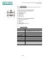
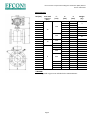
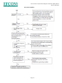
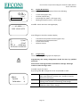
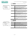
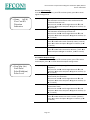
Efcon® Water compact Electro Magnetic Flowmeter (EMF) Manual
Version 231214 UK
Efcon® Water
Installation & User Manual
Electro Magnetic Flowmeter (EMF)
Page 1
Efcon® Water compact Electro Magnetic Flowmeter (EMF) Manual
Version 231214 UK
Table of content
1.1
General
1.2
Application area
1.3
Transportation
1.4
Principle of Operation
1.5
Product Description
Page
3
4
4
4
5
2
2.1
2.2
2.3
2.3.1
2.3.2
2.5
2.6
Installation
Technical specifications
Measurements
Installation
Mechanical installation
Electric installation
Maintenance
Trouble shooting
5
5
6
7
7
8
9
10, 11, 12
3
3.1
3.2
3.2.1
3.2.2
3.2.2.1
3.2.2.2
3.2.2.3
3.2.3
Commissioning
Display & Operation
Programming
Basic settings
System Settings
Signal Settings
Pulse Output settings
Totalizer settings
Calibration settings
13…16
13
13
14
14
15
15
16
16
Page 2
Efcon® Water compact Electro Magnetic Flowmeter (EMF) Manual
Version 231214 UK
1.1
General
Efcon® flowmeters are designed for measuring and controlling
wastewater flows.
Other Products from the Efcon® program are:
Samplers (several types), level controllers, pump controllers, registration
equipment, sample distributor systems, flowmeters industrial and sewers,
measurement pits, cool units, mobile systems, etc.
BEFORE YOU START:
Read the manual before you connect the meter to a power supply or
install.
In case of illegal use or use in non-defined area’s any form of warranty will
be denied. The user needs to be informed about the users manual and
application dangers.
Installing and adjusting parameters of the flowmeter should be done by
qualified personnel.
Check if the equipment is transported without transport damage. In case
of damage directly contact your supplier and do not install the equipment.
The equipment is tested in the Efcon® factory in Hei- en Boeicop,
Netherlands to different quality tests before it is transported. Required
maintenance or repair, which will not influence the warranty period, will
have to be done by trained Efcon® specialists. All equipment returned to
Efcon® needs to be cleaned, sterilised and transported in a safe enclosure
to avoid health-threatening situations. In case of service or repair, the
equipment will not be accepted by Efcon® if there is no declaration of
origin and safety added to the equipment. Extra cleaning can be refused or
will be charged! Warranty will be denied if there are mechanical,
electronic or software changes in the unit which are not performed by
Efcon®.
BASIC WARRANTY PERIODS:
12 months after delivery for Efcon® equipment ex. Works used and
installed according specifications, in a non aggressive well ventilated
environment.
Page 3
Efcon® Water compact Electro Magnetic Flowmeter (EMF) Manual
Version 231214 UK
1.2
Application area
Be aware! Wrong application or misuse can damage the equipment or
the surrounding of the unit and is not covered by any form of warranty.
Surrounding conditions:
•
Temperature: -15°C / + 50°C avoid large changes
•
Well ventilated space
•
Avoid direct sunlight, especially the liquid crystal display
•
Avoid strong vibration
•
Avoid installation near strong electromagnetic devices, such as
large motors, pumps or transformers
Use in explosion hazardous environment is prohibited
unless mentioned on product and manual!
Measured Medium:
•
Especially designed for waste water measurement
•
Minimum fluid conductivity: 50 μS/cm
•
Free of air inclusion
•
Medium temperature range: -40 °C / +150°C.
1.3
•
Transportation
For warranty claims send the system packed in the original
package and on the supplied pallet. All products should be
declared clean and safe to work on.
1.4
Principle of Operation
The operation of a magnetic flowmeter or Mag meter is based upon
Faraday’s Law, which states:
A voltage induced across any conductor as it moves at a right angle
through a magnetic field is proportional to the velocity of that conductor.
Faraday’s Formula:
E=VxBxD
E = Voltage generated in a conductor
V = Velocity of the conductor
B = The magnetic field strength
D = Length of the conductor
To apply this principle to flow measurement with a magnetic flowmeter,
the fluid being measured should be electric conductive.
As applied to the design of the flowmeter, Faraday’s Law indicates
that the voltage E is dependent if the average liquid velocity (V), the
magnetic field (B) and the length of the conductor (distance between
electrodes).
Page 4
Efcon® Water compact Electro Magnetic Flowmeter (EMF) Manual
Version 231214 UK
1.5
Product description
The Efcon EMF Compact Flowmeter consists out of mainly 2 parts: the
sensor tube and transmitter.
The sensor tube consist out of the following parts:
1) Junction box / transmitter mounting flange
2) DN Flange connection
3) Insulted Teflon lining
4) SS Electrodes
5) Measuring tube
6) Excitation coil
7) Protective shell
The transmitter consist out of the following parts:
1) Sensor tube mounting flange
2) Operation lid
3) Display
4) Cursor buttons
5) Swivels for signal & power lines
6) Connection lid
2.1
Product specifications
Sensor Range
Flow Range
Accuracy
Repeatability
Medium Conductivity
Power supply
Power rating
Protection grade
Pulse Output
Current Output
Display language
Control buttons
Low flow cut off %
Damping Time
Auto Trim
Self test function
Page 5
DN10…DN1000
0,05 m/s…10 m/s
±1% >0,5m/s,
(pulse calibrated at 0,1 – 0,5 – 1 – 2 – 5 m /s)
± 0,5%
>50μS/cm
230VAC ±2%
10VA
IP65
Open collector, maximum load 24VDC / 50mA
4-20mA, maximum load <750Ω
English
3
0,0%... 9,9% adjustable (for display or output)
0,1s… 99,9s adjust (for display
Current output self-calibration, empty/full trim. Zero
trim
Current frequency output self test
Efcon® Water compact Electro Magnetic Flowmeter (EMF) Manual
Version 231214 UK
Measurements
DN (mm)
10
15
20
25
32
40
50
65
80
100
125
150
200
250
300
350
400
450
500
600
700
800
900
1000
max work
pressure
(bar)
L*
(mm)
150
25
200
10
250
300
350
400
500
6
600
700
800
900
1000
D
(mm)
K
(mm)
90
95
105
115
140
150
165
185
200
220
250
285
340
395
445
505
565
615
670
780
895
1015
1115
1235
60
65
75
85
100
110
125
145
160
180
210
240
295
350
400
460
515
565
620
725
840
950
1050
1120
* BEWARE:
Gaskets & ground rings are not included in the measurements.
Page 6
Weight
(kg)
4
5
7
8
10
15
20
22
33
43
82
100
121
145
207
210
250
350
460
550
680
Efcon® Water compact Electro Magnetic Flowmeter (EMF) Manual
Version 231214 UK
2.3
Installation
Installation, commissioning and service should
qualified and authorized personnel.
be carried out by
2.3.1 Mechanical:
When installing a flowmeter in a pipe system beware of the following :
•
•
•
•
•
•
The sensor tube should always be 100% filled with liquid medium.
Minimum fluid conductivity: 50 μS/cm
The Free of air inclusion
Temperature range medium: -40 °C / +150°C
Use proper gaskets when making the flange connection.
Use proper grounding
Don’t install:
•
In a downward flow
•
At the highest point in a pipe system
•
In pipe systems not free of air inclusion
•
Avoid vibrations
Page 7
Efcon® Water compact Electro Magnetic Flowmeter (EMF) Manual
Version 231214 UK
Grounding:
Steel/conducting piping:
Connect the supplied yellow/green ground lines(A) on both sides of the
flowmeter to the piping. Ensure the piping is properly grounded.
Plastic or non-conducting piping:
Install the flowmeter with the supplied grounding rings(B), connect these
with the ground lines (A) on both sides. Ensure the rings are placed in the
centre so the flow isn’t interrupted by the ground rings.
2.3.2 Electric:
Before connecting the power supply, check the name plate and
connection terminals, to avoid misoperation and damage the
instrument.
To access and connect the wires to the terminals remove/open the
screw-lid. Ensure when removing the lid the tread doesn’t damage. A
damage tread can make the lid get stuck.
Feed the power line cable and output signal cable through separate
cavities.
Power Supply
•
Connect the ground line to the transmitter to screw with ground
symbol
•
Connect the 230VAC line to the L & N terminals
Current Output
The current output creates an active 4-20mA signal powered from the
transmitter, with 4 mA stands for a flow of 0 m3/h and 20mA stands for
full scale value or Qmax. The maximum current output load is 750Ω.
•
Connect the signal cable (shielded recommended) to terminals I+
and I-.
Page 8
Efcon® Water compact Electro Magnetic Flowmeter (EMF) Manual
Version 231214 UK
Pulse Output
Direct connection to PLC input
Connect the 24VDC wire to the F+ connection of the transmitter, connect
the F- connection of the transmitter to the desired digital PLC-input
(<50mA load).
Pulse Output Connecting to a relay
Use solid state relay and normal relay (Efcon® uses Omron G3R-ODX02SN)
to create a potential free contact from the pulse output. See the diagram
to the left how to wire the relays.
2.4
Maintenance
BE AWARE! Before maintenance or revision switch off power supply,
remove pressure and medium from piping.
Maintenance and reparations should be done by qualified personnel.
Avoid direct contact with wastewater. Wear protective gloves during use,
maintenance and reparation.
Check the inside of the sensor tube regularly and inspect the SS electrodes
inside the tube. Clean inside with a soft cloth.
Page 9
Efcon® Water compact Electro Magnetic Flowmeter (EMF) Manual
Version 231214 UK
2.5
Trouble shooting
No flow data shown in display
Page 10
Efcon® Water compact Electro Magnetic Flowmeter (EMF) Manual
Version 231214 UK
Instrument shows flow data inconsistent with actual flow.
Page 11
Efcon® Water compact Electro Magnetic Flowmeter (EMF) Manual
Version 231214 UK
Zero point instability
50
50
Page 12
Efcon® Water compact Electro Magnetic Flowmeter (EMF) Manual
Version 231214 UK
3.1
Display & Operation
After the first power up the display will show the following:
0,0m /h
3
∑+
0,0m
0%!
3
------ALARM-------
*
*
*
*
Current flow (upper row)
Totalizer positive flow
Percentage flow (100% = full range scale)
Blinking Exclamation mark (= alarm signal)
Press▼ to check the Alarm message display
PIPE LINE EMTY
Press ▼ again to check the totalizer display
∑
0,0m3
∑0,0m3
PV_S
0,000 m/s
E108-4S13-E4NNO
*
*
*
*
Cumulative total positive direction (upper row)
Cumulative total negative direction
Current flow velocity
Software version
3.2
Programming
To access the programming open the display lid.
Programming and setting changements should be done by qualified
personnel.
Ensure when removing the lid the tread doesn’t damage. A damage
tread can make the lid get stuck.
Press ► to enter the menu.
By pressing ▼or ▲to change the cursor and press ► to select.
Basic
→Basic
→
System
→
Calibration →
System
Calibration
Basic settings; change the Pulse value unit, number of
pulse value decimals, totalizer units, number of totalizer
decimals and damping
System settings; change signal settings, Pulse output
settings, clear totalizers, load settings, load settings
Calibration settings; Zero trim, tube trim, loop trim &
calibration factor (don’t change!)
Page 13
Efcon® Water compact Electro Magnetic Flowmeter (EMF) Manual
Version 231214 UK
3.2.1 Basic settings
Press ► to enter the menu, press ► again to enter the basic settings
menu.
→PV Units
PV Decimal
Total units
↓ Total Decimal
PV Units
PV Decimal
Total Units
Total Decimal
Damping
Pulse Value units, select which SI unit to use
Select unit with ▼or ▲ (L/s, L/m, L/h, m3/s, m3/m,
m3/h G/s, G/m or G/h) and press ◄ to select and
press ◄ again to confirm, (or ► to cancel)
Pulse Value decimals, select how many decimals to
use for the pulse value setting,
Press ▼or ▲to select how many decimals are used and
press ◄ to select and press ◄ again to confirm, (or ►
to cancel)
Total Units, select which SI unit to use
Select unit with ▼or ▲ (L/s, L/m, L/h, m3/s, m3/m,
m3/h G/s, G/m or G/h) and press ◄ to select and press
◄ again to confirm, (or ► to cancel)
Total decimals, select how many decimals to use for
the totalizers in the display.
Press ▼or ▲to select how many decimals are used and
press ◄ to select and press ◄ again to confirm, (or ►
to cancel)
Damping time, for display & output
Move cursor with ► and change value with ▼or ▲
and press ◄ to select and press ◄ again to confirm, (or
► to cancel).
3.2.2 System settings
Press ► to enter the menu, press ▼ to select System, press ► to enter
the basic settings menu.
→Signal
→
Pulse Output →
Total Set
→
↓ Load Settings
Signal
Pulse Output
Total Set
Load Settings
Signal settings, Q max (full scale value), low flow cut off
(%), Direction and indication
Pulse output settings, maximum frequency (Hz),
Liters/pulse, Pulse width and pulse level
Clear totalizers, or preset totalizers.
Load factory default settings,
Press ▼or ▲ to change from YES or NO, press ◄ to
select and press ◄ again to confirm, (or ► to cancel).
Page 14
Efcon® Water compact Electro Magnetic Flowmeter (EMF) Manual
Version 231214 UK
3.2.2.1 Signal settings
Press ► to enter the menu, press ▼ to select System, press ► to enter
Signal settings menu.
→Qmax (m3/h)
Low Cutoff%
Direction
Indication
Q max, full scale value, 20mA current flow value.
The maximum and minimum value are bound to the
flowmeter diameter size.
Move cursor with ► and change value with ▼or ▲
and press ◄ to select and press ◄ again to confirm, (or
► to cancel).
Low flow cut off, Fill at what percentage of the Qmax
the flowmeter should keep the flow at 0.
Move cursor with ► and change value with ▼or ▲
and press ◄ to select and press ◄ again to confirm, (or
► to cancel).
Flow direction, choose flow direction.
Press ▼or ▲to select Fwd. (forward) or Rev. (reverse)
press ◄ to select and press ◄ again to confirm, (or ►
to cancel)
Flow indication, select which direction to display
Press ▼or ▲to select Forward or Reverse, press ◄ to
select and press ◄ again to confirm, (or ► to cancel)
Qmax (m3/h)
Low Cutoff%
Direction
Indication
3.2.2.2Pulse Output settings
Press ► to enter the menu, press ▼ to select System, press ▼ to select
Pulse Output, press ► to enter the Pulse Output settings menu.
→Freq Max (hz)
Liter/Pulse
PulseWidth(ms)
Pulse Level
Freq Max (Hz)
Liter/Pulse
PulseWidth(ms)
Pulse Level
Maximum pulse frequency, fill in the maximum pulse
frequency
Move cursor with ► and change value with ▼or ▲
and press ◄ to select and press ◄ again to confirm, (or
► to cancel).
Liter / Pulse value, enter the desired volume per pulse
measured by the flowmeter.
Move cursor with ► and change value with ▼or ▲
and press ◄ to select and press ◄ again to confirm, (or
► to cancel).
Pulse Width, enter how long the pulse output remains
active when active.
Move cursor with ► and change value with ▼or ▲
and press ◄ to select and press ◄ again to confirm, (or
► to cancel).
Pulse Level
Press ▼or ▲to Active H or active L or Rev. (reverse)
press ◄ to select and press ◄ again to confirm, (or ►
to cancel)
Page 15
Efcon® Water compact Electro Magnetic Flowmeter (EMF) Manual
Version 231214 UK
3.2.2.3 Totalizer settings
Press ► to enter the menu, press ▼ to select System, press 2x ▼ to
select Total Set, press ► to enter the Totalizer settings menu.
Clear Total
→Clear Total
FWD Preset (m3)
REV Preset (m3)
FWD Preset
(m3)
REV Preset
(m3)
Clear Totalizer, clear the totalizer
Press ▼or ▲to No or Yes, press ◄ to select and press
◄ again to confirm, (or ► to cancel)
Forward Preset, enter a value to change the forward
totalizer.
Move cursor with ► and change value with ▼or ▲
and press ◄ to select and press ◄ again to confirm, (or
► to cancel).
Reverse Preset, enter a value to change the reverse
totalizer.
Move cursor with ► and change value with ▼or ▲
and press ◄ to select and press ◄ again to confirm, (or
► to cancel).
3.2.3 Calibration settings
Press ► to enter the menu, press ▼ to select System, press 3x ▼ to
select Calibration, press ► to enter the Pulse Output settings menu.
Before Zero Trim, the flowmeter sensor tube needs to be filled with
medium and be in quiescent state. The flowmeter needs to be powered
for more than 15 minutes (warm-up time).
→Zero Trim
Tube Trim
Loop Trim
K Character
Zero Trim
→
→
Tube Trim
Loop Trim
K Character
Fast Calibration method, to correct the flow
measurement.
Press ▼or ▲to select Yes press ◄ to select and press
◄ again to confirm, (or ► to cancel)
Tube Trim manual calibration method, trim empty
pie, full pipe & Tube region-%.
Loop trim, adjust the 4-20mA output signal, for 4mA
and 20mA
Don’t change keep on 1.00000
Page 16