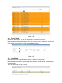
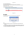
1
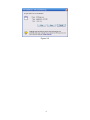
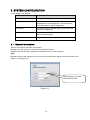
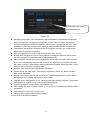
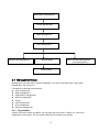
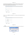
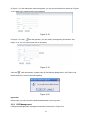
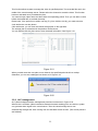
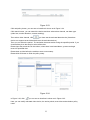
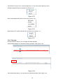
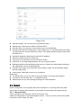
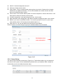
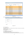
DSS Manager User’s Manual (Base)
Mobile Version
Table of Contents
1
GENERAL INTRODUCTION ........................................................................................ 5
1.1
Glossary ...............................................................................................................................................................5
1.2
Overview ..............................................................................................................................................................5
1.3
Network Connection ...........................................................................................................................................6
1.4
Environment.........................................................................................................................................................6
1.4.1
Server ..............................................................................................................................................................6
1.4.2
Manager Client-end .......................................................................................................................................6
2
LOG IN ......................................................................................................................... 7
2.1
Preparation ..........................................................................................................................................................7
2.2
Log in ....................................................................................................................................................................7
3
SYSTEM CONFIGURATION...................................................................................... 10
3.1
General Introduction .........................................................................................................................................10
3.2
Management Setup ..........................................................................................................................................12
3.2.1
Organization..................................................................................................................................................12
3.2.2
Device Management....................................................................................................................................13
3.2.3
Group Management.....................................................................................................................................15
3.2.4
User Management........................................................................................................................................17
3.2.5
CSP Management........................................................................................................................................19
3.2.6
ALP management ........................................................................................................................................20
3.2.7
E-map ............................................................................................................................................................22
3.2.8
Decoder .........................................................................................................................................................27
2
3.3
System................................................................................................................................................................28
3.3.1
General Setup...............................................................................................................................................28
3.3.2
Server Setup .................................................................................................................................................29
3.3.3
Upgrade Management.................................................................................................................................31
3.4
Running Status..................................................................................................................................................31
3.4.1
Alert Information ...........................................................................................................................................31
3.4.2
System Log ...................................................................................................................................................32
3.4.3
Device Status................................................................................................................................................33
3.4.4
User Status ...................................................................................................................................................33
3.4.5
Decoder Status List......................................................................................................................................34
3.5
Log out................................................................................................................................................................34
3
Welcome
Thank you for using our software!
1 GENERAL INTRODUCTION
In this chapter, you will find:
Heading
Content
错误!未找到引用源。
Glossary
Introduce the term definition concerning this user’s
manual.
错误!未找到引用源。
Overview
Introduce DSS (Digital Surveillance Software)
system overview.
1.3 Network Connection
Network structure, environment and etc.
1.4 Environment
Server and manager client-end environment
requirement
1.1 Glossary
English
Abbreviation
Definition
Central management software.
CMS
System management, server management,
operation realization, system allocation and
storage policy implement.
MTS
Audio/video data transfer, support stream
media.
SS
Audio/video data central storage, playback
and front-end record playback.
DMS
Device configuration, PTZ control, device
alarm receive and send out.
CU
Monitor key operation. Real-time monitor,
PTZ control, record playback, monitor plan
and alarm activation.
MU
Device
management,
user
name
management, user group management,
organization
management,
system
management, system log and running
status.
1.2 Overview
DSS (Digital surveillance software) is monitor software of strong function. It embedded multiplewindow, multiple-user and various languages. It supports audio talk, E-map, alarm centre and
matrix output. DSS is compatible with other extension devices. It has high reliability, friendly user
interface, high flexibility and sound expansibility.
The DSS platform can connect to various devices or models (such as DVR, IPC, NVS and etc).
This user’s manual applies to the manager client-end only.
DSS supports the following devices: DVR、NVS、IPC and IPS series.
5
1.3 Network Connection
Please refer to the network connection sample. See Figure 1-1.
Figure 1-1
1.4 Environment
1.4.1 Server
Hardware
① CPU Core2 Duo 2.2G
② Memory 2G
③ HDD 120G free capacity (This HDD can not be used as the storage
HDD)
④ 1000M Ethernet dual network card
Software
① Microsoft Windows 2003 Server SP2, 4G or higher version,
② Internet Explorer 6.0
1.4.2 Manager Client-end
Hardware
① Intel C4 1.7
② Memory 512M
③ HDD 1G free capacity
④100M Ethernet card
Software
① Microsoft Windows 2000
② Internet Explorer 6.0 DirectX 8 or higher
6
2 Log in
In this chapter, you will find:
Heading
Content
错误!未找到引用源。
Preparation
Something you need to know before log in to the
DSS.
错误!未找到引用源。Log
in
Introduce DSS log in steps.
2.1 Preparation
Before you log in, please make sure:
z
z
z
z
z
PC and encode device connection is right.
DSS server and encode device network connection is O.K.
DSS service has booted up.
DSS server and encode device has been connected.
There is no other software or management platform in the encode device.
2.2 Log in
There are two ways for you to log in.
Input the following address in the IE address column:
http://serverIp:8080/dss/admin
The serverip is your web server IP. 8080 is system default access port.
The click Enter button, you can go to an interface shown as in Figure 2-1.
The other way is double click the DSS Manager icon in the desktop and then you can see an
interface is shown as in Figure 2-1.
7
Figure 2-1
Please input user name, password and authentication code to log in.
Default user name is system, password is 123456.
The main interface is shown as in Figure 2-2.
Note:
z Before log in, please make sure the platform server has booted up.
(Tomcat\CMS\DMS\MTS\SS)
z For security reasons, please modify the password after you first logged in.
Click here to add or hide
the sub-menu.
Figure 2-2
If it is your first time to log in, system may pops up a dialogue box asking you to install the plugin.
In Figure 2-2, you can click here button to download the latest OCX.
System pops up the following dialogue box for you to install. See Figure 2-3.
8
Figure 2-3
9
3 SYSTEM CONFIGURATION
In this chapter, you will find:
Heading
Content
3.1 General Introduction
DSS system general introduction
3.2 Management Setup
It includes organization, device management, group
management, user management, e-map, decoder,
ALP management, CSP management.
3.3 System
It includes domain, general setup, server setup and
upgrade management.
3.4 Running status
It includes alert information, system log, device
status, decoder status.
3.5 Log out
Log out DSS.
3.1 General Introduction
There are two levels: manager and operator.
Manager can add, remove or modify client-end device and etc.
Operator can monitor video, playback recorded file and etc in the client-end.
Note:
Manager account and operator account can not be mixed used in these two log-in interface. See
Figure 3-1 and Figure 3-2.
Input Manage user name
and password here.
Figure 3-1
10
Input operator user name
and password here.
Figure 3-2
z
Manager right includes: user management, right management, organization management,
device management, storage plan management, E-map, alarm activation management,
decoder management, general management, service setup, upgrade management, alarm
information, system log, system device status list, decoder status list and user status list.
z Organization management: According to the whole monitor structure, set corresponding
organization to manage conveniently.
z Device management: For user to add front-end DVR, NVS, and IPC.
z Storage plan management: it is for centre platform to storage the data from the front-end
and auto storage to the redundant array of independent disks.
z Alarm activation management (ALP management): When there is an alarm from front-end
device, the corresponding camera in the front-end can begin auto record (alarm activates
the centre to record). The activation alarm includes external alarm, video loss alarm, motion
detection alarm and camera masking alarm.
z Decoder: Add, remove and modify decoder information.
z General setup: Set CMS server, auto-number, compulsive I frame, log, alert information,
Web server and DDNS.
z Service setup: Set median transfer server (MTS), centralized storage server (SS), device
management server (DMS), video matrix server (VMS).
z Upgrade service management: it is to control and manage client-end upgrade. The operator
auto updates to the latest version after the client-end upgrade.
z System log: Memory system running and operation log.
z Device status list: View front-end is online or not, and view its corresponding platform basic
information.
z User status list: check user is online or not.
z Decoder status: Display all decoders’ statuses.
You can refer to the following diagram.
11
Organization Management
Device Management
Right Management
User Management
Storage Plan Management
General Setup
Alarm Activation Management
(ALP Management)
Service Setup
3.2 Management Setup
Management is the first step of system initialization. It is also an important part of the system
management. See Figure 3-3.
It includes the following seven sections:
z User management
z Right management
z Organization management
z Device management
z E-map
z CSP management
z ALP management
z Decoder management
3.2.1 Organization
System root name is blank by default, you can input root name here. In Figure 3-3, there is an
organization of two levels. The root name is WEB and it consists of two groups.
12
In organization management, you need to nest the management layer one by one and the last
child nod shall set according to the device actual position. Usually, one zone or one department
is nested in one group nod. System supports max 255 levels.
Figure 3-3
Click
, you can modify the nod name and its corresponding information.
Click
, you can add a node.
Please note, you can only delete the non-node item. Click
, system pops up the following
dialogue box. See Figure 3-4. Click OK to remove the selected nod.
Figure 3-4
Note:
Delete one node; you will delete all its included child nodes at the same time!
If the last node is the device, system also pops up the above dialogue box.
3.2.2 Device Management
This interface allows you to manage all devices.
Click device management button, you can see an interface is shown as in
Figure 3-5.
13
Figure 3-5
Click add device button, you can see the following interface. See Figure 3-6.
z Device ID: System automatically generates one device serial number (It ranges from
1001025). Please refer to chapter General Setup to set a self-defined number.
z Device Type: There are four options: DVR/IPC/NVS/MCD. MCD is virtual device to connect
to the alarm host and the multiple control devices.
z Device Name: Please input a device name here.
z Memo: You can input some simple description here.You can just leave it in blank.
z Manufacturer: You can select from the dropdown list. Right now there is one option 1.
z Model: Input device model here.
z Channel Amount: There value ranges from 1 to 256. (Please make sure the number amount
before you input. It can not be modified.)
z Alarm Input Amount: There value ranges from 1 to 256. (Please make sure the number
amount before you input. It can not be modified.)
z Alarm Output Amount: There value ranges from 1 to 256. (Please make sure the number
amount before you input. It can not be modified.)
z Device IP: Please input device IP here. If you enabled DDNS, you can just input DDNS map
name.
z Device Port: Default value is 37777.
z
User Name: Please input log in name here. It shall support reuse (E.g., multiple users
can use this account to log in at the same time.)
z Password: Please input corresponding password here.
z Belong to: Please select the organization the device belongs to. (Here only displays the
organization tree manager belongs to and its corresponding sub-tree.)
z Channel setup: Here you can input channel name and then select channel type(General
camera, speed dome and half speed dome)
z Alarm Setup: You can input alarm input name and then select alter type. For alarm grade:
There are three options.
z Alarm output Setup: Here you can input an alarm output name for respective channel. You
can draw a circle to enable alarm function. You can also click ALL/Cancel button to select or
cancel all channels. For alarm type, you can select from the dropdown list. There are two
options: Normal open/Normal close.
Note: You need to input the corresponding information in item with *, otherwise system pops up
warning when you save current setup.
Important
The system will automatically save the GPS information for 30 days.
14
Roll down to view
more information
Figure 3-6
3.2.3 Group Management
The user in the same group has the same rights and one user can belong to several groups.
The group management also has two levels.
Manager has the system configuration rights and operator has management rights.
Click group management icon, you can see an interface is shown as in
Figure 3-7.
15
Figure 3-7
In
Figure 3-7, click add button near the administrator group. You can see an interface is shown as
in
Figure 3-8. Manager right includes: user name, right group management, organization, device
management, storage plan, alarm activation, general setup, service setup, update service,
system log, device status and user status.
Please draw a circle before corresponding item and then click OK button to exit.
16
Figure 3-8
In
Figure 3-7, click add button near operator group, you can see an interface is shown as in Figure
3-9. Please input operator group name here (such as overseas) and then select group level
(Level1 to Level 5). Finally you can click OK button.
Figure 3-9
Note:
Please follow the steps to set corresponding rights for newly added user; otherwise you
can not use this user!
Go back to
17
Figure 3-7, click
near the operator overseas. You can see an interface is shown as in
Figure 3-11.
Figure 3-10
You can select device from the dropdown list and then enable the corresponding operation rights
(such as channel monitor right, playback right, PTZ control right, alarm channel control right and
etc)
Then you can view the device name and IP address you have granted to current operator.
Figure 3-11
In Figure 3-7, click
near the operator, you can edit operator information. See Figure 3-12.
18
Figure 3-12
In
Figure 3-7, click
near the administrator, system pops up the following dialogue box. See
Figure 3-13. Click OK to remove selected group.
Figure 3-13
3.2.4 User Management
Click user management button, you can see an interface is shown as in Figure 3-14.
The user management includes two levels: administrator and operator.
19
Figure 3-14
Click add button near the administrator, you can see an interface is shown as in Figure 3-15.
Here you can input administrator name and password. Then select corresponding groups
(multiple choices). Please click OK to save current setup.
Figure 3-15
In Figure 3-14, click
near the administrator, you can modify current administrator information.
See Figure 3-16.
Figure 3-16
Click
near the administrator, system pops up the following dialogue box. See Figure 3-17.
Figure 3-17
20
In Figure 3-14, click add button near the operator, you can see an interface is shown as in Figure
3-18. Please input operator name and password.
Figure 3-18
In Figure 3-14, click
near the operator, you can modify corresponding information. See
Figure 3-19. You can lock current user if necessary.
Figure 3-19
Click the
near the operator, system pops up the following dialogue box. See Figure 3-20.
Please click OK to remove selected operator.
Figure 3-20
Important!
Please note you can not remove default administrator account system.
3.2.5 CSP Management
CSP(central storage plan) management interface is shown as in Figure 3-21.
21
This function allows system to storage the video in specified period. The recorded files are in the
media of the central storage server. Please select the channel to record the video. This function
becomes activated once you added the plan.
You need to input a plan name and then select corresponding period. Then you can draw a circle
before the enable item to activate the setup.
Please note, if the period is not within one day (E.g. from 00:00 to 24:00), you need to draw a
circle before the next day button.
Click add button, you can view the central storage plan on the right side.
The storage plan is memorized in the platform central server.
You can double click the plan name to view the detail information. See Figure 3-21.
Figure 3-21
When you add more than one plan to one channel, the specified period shall not overlap.
Otherwise, you can see a dialogue box shown as in Figure 3-22.
Figure 3-22
3.2.6 ALP management
ALP (Alarm linkage/activation management) interface is shown as in Figure 3-23.
When there is an alarm (video loss/motion detection/camera masking) from one device, system
can generate alarm signal to the central server. Then the central storage server can
automatically storages the video coming from the activated record function. (The record period is
self-defined)
22
Figure 3-23
Click add policy button, you can see an interface is shown as in Figure 3-24.
Click search button, you can search the device and then select alarm channel, set alarm type
(video loss, motion detection, camera masking).
Then select video channel, click
, you have set the activated alarm device (One alarm
device can support several video device as the activation device.)
Then you can select the period. The activation becomes active during the specified period. If you
choose all day then the setup is active all the time.
Please input the record time in the column, when there is activated alarm, system can begin
record for specified time.
Please draw a circle before the enable to save current setup.
Please click OK button to finish the policy setup.
Figure 3-24
In Figure 3-23, click
you can see an interface is shown as in Figure 3-25.
Here you can modify activated video device, the active period, record time and activation policy
name.
23
Figure 3-25
Click
near the activation policy, system pops up the following interface. See Figure 3-26.
Click OK button to remove the selected policy.
Figure 3-26
3.2.7 E-map
E-map provides three modes to display the nod: E-map, preview and device tree.
Please refer to Figure 3-27.
24
Preview
Device
Tree
E-map Display Window
Click button here to add
e-map
Figure 3-27
In the E-map, you can see the device position and current status. Double click the e-map nod,
you can see the property dialogue box. Here you can the detail information of the nod. See
Figure 3-28.
Figure 3-28
Please note different e-map nods have different property interface.
25
The e-map nod consists of four modes: domain, camera, alarm channel and sub-e-map. The
camera consists of general camera, speed dome, IP camera, network video server and so on.
In Figure 3-27, click picture edit button, you can see the following interface. See Figure 3-29.
Figure 3-29
Click add button, you can see an interface is shown as in Figure 3-30. Here you can input picture
name (such as Shanghai), picture title and then select picture path. Please click OK button to
save current setup.
Figure 3-30
System goes back to Figure 3-29, please click OK button to exit.
After you finished the above steps, click picture button in Figure 3-27. Now you can see you have
added an e-map (Shanghai). Repeat above steps to add more e-maps. See Figure 3-31.
26
Figure 3-31
In figure 3-31.select the e-map Shanghai and then drag it to the right section. You can add one
e-map to the domain.
In Figure 3-31, select e-map Shanghai2 and then drag it to the display section. Now you can see
an interface is shown as in Figure 3-32.
Figure 3-32
In Figure 3-32, click device button, and then drag the channel number to the e-map and then
release. You can see the following interface. See Figure 3-33.
You can see you have added a camera in the e-map (The red circle one.)
Important
Always remember clicking save button in Figure 3-24 to save current e-map setup!
27
Drag the rectangle here to
adjust the display content.
Select a camera here.
Drag your mouse to the emap and then release.
Click button here to
remove the e-map.
Click device button here.
Click save button here
to save current e-map
setup.
Figure 3-33
Click Clear Mapdata button on the right bottom, system pops up the following dialogue box. See
Figure 3-34.
Figure 3-34
Click YES button, you can remove all e-map background and all nods.
Tip:
Move the green rectangle icon in the preview section; you can view different e-map content in
display section.
You can repeat the above procedures to add a sub-map.
If you want to implement multiple sub-e-maps setup, you can follow the procedures below:
z Open one map such as map1.
z Click picture button and drag map 2 to anywhere in map1.
z Click map button and click map 2 to open current map
z Double click device name on your right side to add one device to map 2.
z You can view newly added e-map and device list in the map list section.
z Click save button, now you have added one sub-map and its device.
28
Click different e-map nod or e-map background, you can view various right-key menu.
Domain background menu is shown as in Figure 3-35.
Figure 3-35
Sub e-map background menu is shown as in Figure 3-36.
Figure 3-36
Speed dome, IPC, alarm channel menu is shown as in Figure 3-37.
Figure 3-37
3.2.8 Decoder
Decoder interface allows you to manage all armed decoders.
Click Decoder Manger, the interface is shown as below. See Figure 3-38.
Figure 3-38
Click add decoder button, you can seen the following interface. See Figure 3-39.
29
Figure 3-39
z
z
z
z
Decoder Number: You can input your self-defined number.
Decoder type: There are two options: NVD and SNVD.
Decoder name: You can input a name here for your own identification.
Decoder output amount: Please input a value ranges from 1 to 16. Please note the number
you input here can not be modified in the future. The system total NVD output number shall
be less than 32.
z Decoder IP address: Please input current NVD IP address.
z NVD port: Please input port number here.
z User name: The user name you use to login the device.
z Password: The corresponding password you use to login the device.
z Belonging position Select decoder belong structure. System here only displays manager’s
the organization tree and its belonging tree:
z Decoder output setup: input a decoder output number, system can automatically display
decoder output setup.
z Output name: Pleas add a name for your reference.
Please note:
z For SNVD series, you do not need to input port number, user name and password.
z You need to fill in all items with * to complete the setup.
z Please make sure you are inputting according to the actual situation.
3.3 System
System configuration is an important part of the management. It is mainly about the system
server setup. It includes three modules: normal setup, services setup and upgrade service.
3.3.1 General Setup
Click normal button, the interface is shown as in Figure 3-40.
CMS is an abbreviation for central management server. It is a key server for the whole system
and the key of MTS, DMS, SS, VMS.
30
z
z
z
CMS IP: Central management server IP.
CMS port: Default value is 9000.
Auto number: This is a serial number system gives to the device. Please refer to chapter
Add Device for detailed information. You can also disable auto number function and then
input your self-defined start number.
z Force I frame: This function allows system to use the compulsive I frame of the device. It can
help open the video for devices you have used.
z Log max storage time: Input log storage time here. Unit is month.
z Alert information max storage time: Input alert information storage time here. Unit is month.
z DDNS: if you want to use DDNS function. You need to get server IP (PC IP), server port
value (default value is 7070) and protocol (default value is 1).
z Web server IP: You can set Web server local host IP and WAN IP.
Please contact our technical support group for detailed DDNS server information.
Roll down to view
more information
Figure 3-40
3.3.2 Server Setup
The server setup interface is shown as in Figure 3-41. This interface allows you to manage all
the serves in the system. All are established by default when you install the DSS. Usually we
recommend you do not modify the service setup.
31
Figure 3-41
Click add server button, you can see the following interface. See Figure 3-42.
Please select the type first: MTS,SS, DMS, VMS(you need to set MTS、SS、CMS
respectively by default.)
z IP: Please input server IP. The format shall be xxx.xxx.xxx.xxx.
z SN: Here you can input serial number to manage servers. Recommended serial number
principle is: MTS: 100+1 (begins from 101). SS: 200+1.DMS:300+1.VMS:400+1. Please
make sure the server (MTS,SS, DMS, VMS)serial number is unique.
z Name: Usually it is the type such as MTS.
z Organization: It is a root organization by default and can not be modified.
z Bandwidth: There are three options: 10Mps, 100 Mps, 1000 Mps.
z Password: Server login password.
Figure 3-42
Click
of the corresponding server, you can modify server information. See Figure 3-43.
You can modify IP, name, organization, bandwidth, password and memo.
Figure 3-43
Click
of the corresponding server, system pops up the following dialogue box. See Figure
3-44.
32
Figure 3-44
3.3.3 Upgrade Management
It is to upgrade the client-end. The operator client-end automatically upgrade to the latest version
after you update the client-end program here.
Click upgrade management, system goes to the following interface. See Figure 3-45.
Figure 3-45
Click browser button to open upgrade file and then input version number. Please click OK button
to begin update. You can view the file name, path, update time, file size and running status at the
bottom of the interface.
3.4 Running Status
Running status includes alarm information, system log, device status list and user status list.
3.4.1 Alert Information
Click alert message button, you can select some conditions such as structure, device, device
channel, alarm time and alarm type to search alarm message. You can view the following
interface. See Figure 3-46.
33
Figure 3-46
Click one alarm message; you can view the detail information. See Figure 3-47.
Figure 3-47
3.4.2 System Log
Click log button, you can see an interface is shown as in Figure 3-48. Here you can view device
status and user status.
System log includes the three types:
z System event
z Administrator operation for the system.
z Administrator log in information.
Generally speaking, there are system log, operation log and event log.
You can search by selecting corresponding type (Log period/log type/activation log in name).
34
Figure 3-48
3.4.3 Device Status
Click device status button, you can see an interface is shown as in Figure 3-49.
Here you can view device serial number, name, type, channel amount, IP address, organization
and its status. You can quickly find the malfunction device here.
Figure 3-49
3.4.4 User Status
Click user status button, you can see an interface is shown as in Figure 3-50.
Here you can view all operator status and get online operator, operator amount, locked amount
and total amount.
Yellow font means current user is online.
35
Figure 3-50
3.4.5 Decoder Status List
Click decoder status button, the interface is shown as below. See Figure 3-51.
Here you can view current decoder serial number, name, type, output amount, IP address,
belonging position, status.
The red font means current device is offline.
In this interface, you can quickly find the malfunction decoder.
Figure 3-51
3.5 Log out
Click log out button, system pops up the following interface. See Figure 3-52.
Click OK to exit DSS.
Figure 3-52
Note
z This user’s manual is for reference only. Slight difference may be found in user
interface.
z All the designs and software here are subject to change without prior written notice.
z If there is any uncertainty or controversy, please refer to the final explanation of us.
z Please visit our website for more information.
36