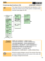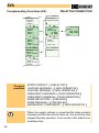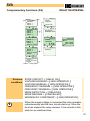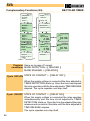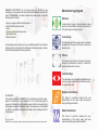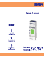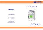
1
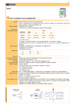
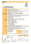
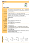
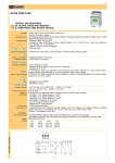
User’s manual F Segle XX, 91 E08032 - Barcelona ( T: +34 934 560 995 F: +34 934 354 532 ü www.disibeint.com [email protected] Digital control relay SVA DISIBEINT ELECTRONIC S.L, has been present in the field of the manufacture of components for the industrial automation for more than 35 years, and maintains in constant evolution their wide range of products structured in five families: · Sensors, magnetic switches and transducers · Level relays for liquids and solids ·Timers · Control, surveillance and logic relays · Digital control relay · Data transmission Our permanent preoccupation is to give a suitable answer to the problems that appear in the automation of the different industrial processes, providing the most suitable material for each application. Manufacturing program Sensors A wide variety of types of sensors allows an easy way to find out the efficient solution for the control of the level in a large number of products. Level relays Its combination with the level sensors is the suitable complement for the control of the level in wells, tanks and reservoirs. Timers From the common functions of timing and passing through the multifunction models, it is arrived to elements with specific functions Control relays This wide family who contributes to confidence and yield in complex installations where the security is the essential element. Programmable controllers GUARANTEE The products provided by DISIBEINT has a guarantee period of two years, against all defect due to the materials or to the manufacture of the equipment. It does not cover the defects caused during the transport or by a bad application, neither the elements subject to wearing down, nor the direct or indirect consequences caused in the installation by the inadequate use of the equipment. Rev.01/00 · 22/09/2011 DISIBEINT reserves the right to modify the specifications stated in this document without previous notice. This family of controllers combines the own characteristics of the classic relays and improve them by adding new benefits. Data transmission This family of controller combines the own characteristics of the classic relays and them improvement adding sophisticated benefits. SVA INDEX Description and parts of the equipment ................................................... 2 Technical data ...................................................................................... 3 Quality certificate .................................................................................. 5 Conventions used in this manual ............................................................. 6 General concepts ................................................................................. 7 Types of screen ................................................................................... 8 Fast guide for beggining ........................................................................ 13 User programs ..................................................................................... 14 Advanced programming ........................................................................ 17 MENUS AND SCREENS Set up menu ......................................................................................... Total number of modules ........................................................................ State of the relay’s contact ..................................................................... State of the relay in alarm mode ........................................................ Detection/Release by modules .......................................................... Detection and release module ........................................................... Detection and/or release timing ......................................................... Reading units .................................................................................. Top of scale ..................................................................................... Loop 4-20 mA .................................................................................. RS485 ............................................................................................. Options menu ................................................................................... Save program .................................................................................. User program .................................................................................. Programs 1 and 2 ............................................................................ See screen ...................................................................................... Edition of the user screen .................................................................. Information of the model and version ................................................. Screen refresh ................................................................................. Locking parameters ......................................................................... Language ........................................................................................ Complementary functions ................................................................. Error messages ............................................................................... Outputs communication ................................................................... Your notes ....................................................................................... 18 19 20 21 23 25 27 30 32 33 34 35 36 37 38 39 40 41 42 43 44 45 49 50 52 SVA DESCRIPTION OF THE EQUIPMENT The model SNI is a controller of the level for liquids. The detection and control system is based on the combination of the MPS sensor with the controller SNI. In the sensor MPS there is a certain quantity of modules (from 1 to 80) connected in series and separated among themselves for the distance that the user decides. A float that moves along of the guide tube takes care of activate or to deactivate the contact placed in each module. The signal generated by this effect is processed in the controller SNI in such a way that is possible to configure the actions to perform when the float goes to the position of a determined module. These actions can be associated to three relays, to 4-20mA loop or to a communication series RS232 or RS485. PARTS OF THE EQUIPMENT Phases input Options’ selection Screen’s selection Change of values Text edition Supply voltage input LCD screen Enter Signaling of the supply voltage and state of the relay 2 Relays output SVA TECHNICAL DATA (1/2) Function Voltage relay for single-phase lines. Control of own supply voltage. Working mode User configurable. Each of the three relays available can be assigned its drive for one or more magnitudes, making it the first situation to occur. Display to By the following status displays: read value TENSION: Tension línia. FREQUENCY: Frequency of the line. DC COMPONENT: continuous component of the line Output - From 1 .. 3 independent relays - Analog 4-20 mA (optional) - Communication RS232 - RS485 (optional) Detection/ All figures may be designated the detect and/or replacement value. Release Timer It is associated with the action of the relay. Adjustable detection and/or replacement. Multiple functions. Repeatibility ± 30 ppm Time range 0,01..99,99 s 0,01..99,99 m 0,1..999,9 h Precision Taken on the value being measured VAC 50 Hz: 0.7% · 60 Hz: 0.8% Frequency 0.3% Precision 1% additional to the equipment value. 4-20 mA Connection Dimensions 3 SVA TECHNICAL DATA (2/2) Output relays 18 28 38 1 2 Supply voltage L ~ A1 3 A2 15 25 35 AC 6 A / 240 V Resistive 6 A / 24 V DC load AC 3 A / 240 V Inductive DC 3 A / 24 V load > 106 oper. Mechanical life Mech. switching rate 18.000 oper. / hour 360 oper. / hour Elect. life at full load AgSnO Alloy Contact material 240 VAC (85 ºC) Operating voltage 1000 VAC Volt. between contacts 4000 VAC Volt. coil/contact Isolation resistance > 100 MW (500 VDC) 1 red led for relay Indication N Galvanic isolation No Frequency 43..70 Hz Operating margins ±10% -15% Consumption 2,5 VA Power on time 100 ms 96,6 ms 25 ms 21,6 ms Detection time Reset 1 net cycle or -30% to nominal voltage Indication Green led Constructives and ambientals dats Overvoltage category Rated impulse voltage Pollution degree Protection Approximate weight Storage temperature Operating temperature Humidity Housing Socket Leds cover Button, terminal block, clip Pins of the terminal block Approvals 4 I I I (EN61010) 4 kV 2 (EN61010) IP 20 280 g -30..+80ºC -20..+50ºC < 95% HR Cycoloy - Light grey Lexan - Transparent Technyl - Dark blue Brass 0,8 Nm Designed and manufactured under EEC standards. Electromagnetic compatibility , directives 89/366/EEC and 92/31/EEC. Electric safety, directive 73/23/EEC. Plastics: UL 91 V0 SVA QUALITY CERTIFICATE The company DISIBEINT ELECTRONIC S.L. Segle XX, 91 E08032 Barcelona (Spain) CIF: B60893849 declares unders its sole responsability that all the products included in its general catalogueand grouped under the generic denominations - Sensors Level Relays Timers Control Relays Programmable Controllers and with the brand name DISIBEINT are manufactured following the company's quality and procedures manuals, which are drawn up according to the ISO9001 standards' specifications. Additionally, the above-mentioned products are marked with the logo and are in conformity with the Directive of Electromagnetic Compatibility EMC 89/366/EEC and with the Low Voltage Directive LVD 73/23/EEC. EMILIO JOLIS OLIVA Director Barcelona, 1st October, 2005 5 SVA CONVENTIONS USED IN THIS MANUAL Symbols i ! It refers to the information own of the theme that is treated. Indicate important warnings to take into account. It refers to how the keys must be pressed to perform the actions indicated in the examples. General information about the controller or about this manual, too. Screens In the pages where is explained how to access to the different screens and menus (pages 18..44), it is shown the way to come to the resolution of every option. This way is highlighted by a dark background of the of the screens related in that option. The union of several screens by means of a dashed line, means that the option is valid for all of them. 6 SVA GENERAL CONCEPTS Loop 4-20 mA (optional): The value sent by the 4-20mA loop can be whichever of the following ones: - Voltage - Frequency - DC component See the page 30-31 to associate a value to the current loop. Communication with PC (optional): It is possible to communicate to the controllers SVO and SVP with a computer via the serial port RS232 for its remote programming or to process the data that it generates. For a standingalone communication, the programming interface CBPZ is required. For a multiple communication (up to 31 equipments) an RS232-RS485 conversor must be used, reference SBAZ. Display’s illumination: The display remains illuminated while its is accessed to the different screens. If a key is not pressed for longer than 30 seconds, the light turns off. In order to turn the light on, it is enough to press any key once only. Working mode: After setting up the controller’s parameters, it can be back to the normal working mode by executing the option RETURN from the SET UP menu. The status screens can be also visualized if any key is not pressed for longer than 3 minutes. Interactive menus: Only those options that can be configured are accessible in menus, being the rest of the they no visible. This characteristic is interactive, this is, that it’s produced automatically in function of the active options at each moment. Change of values: The screens used to change a numerical value contain the margins between that value can be adjusted. These margins can depend on another options, so that they can visualize different values in function of another previous relations. Assignation of magnitudes: Each relay can be activated by the control of one or various magnitudes. For exemple, it can be assigned to RELAY 1 the action by maximum voltage and minimum frequency, althongh when the relay is activated, it’s not possible to know which magnitude has provoked it. 7 SVA TYPES OF SCREENS (1/5) 1.1 Status screen 2 3 VOLTAGE 24.00 18.00 Number to current screen Number to total screens Name of the magnitude Current value Vdc 30.00 Units Maximum limit Graphical bar Minimum limit The status screens show the actual values of the magnitudes that the equipment controls . In the normal working mode, the equipment shows the status screen that the user has chosen like preferring magnitude of visualization. In order to move around among the different status screens of status, press . By pressing from anyone, it is entered to the set up menu. The default status screen is the one shown when the equipment is powered or when any key is pressed for longer than 3 minutes. To select it, execute the option SEE SCREEN (see page 37). 1.2 User screen USER SCREEN WRITE HERE YOUR TEXT PERSONALIZED The text edited in the user screen is the one that will be shown next to the status screens when the equipment is i the normal working mode. The characters that can be used are the following: ABCDEFGHIJKLMNOPQRSTUVWXYZ ÅÆßÇÑØ-/#%<=>0123456789 Pressing and the desired character is selected and becomes validated by pressing , moving up to the following position of the right hand or to the line below. The repeated pulsation of provokes the advance of the cursor.. ! 8 A validated character can not get modified, that means that is not possible to move back. In order to modify a text, is necessary to enter again into the edition screen. In order to abandon this screen is essential to advance until the last position of the last row. SVA TYPES OF SCREEN (2/5) 2.1 Screen of options menu 4 7 SET UP RETURN RELAY 1 RELAY 2 RELAY 3 Number to selected option Number total of options Title of the menu Description of the options 2.2 Selection of options menu Are those in which a series of options is visualized, line by line. The selection of one option carries to a new menu. The digits placed at the top of the screen indicate, from top to down, the number of the selected option and the total number of options. The options are disposed in an endless loop, in such a way than after the last option it comes to the first one of the series. In the same way, moving back from the first option it comes to the last one of the series. 1 12 RETURN RELAY 1 RELAY 2 RELAY 3 Press the keys until the cursor indicate the desired value and to validate it and jump to a new menu. In order to abandon a menu of options and to return the preceding screen, the option RETURN must selected. 2 12 SET UP RELAY 1 RELAY 2 RELAY 3 OPTIONS 3 12 SET UP RELAY 1 RELAY 2 RELAY 3 OPTIONS 4 12 SET UP RELAY 2 RELAY 3 OPTIONS LOCK 5 12 SET UP RELAY 3 OPTIONS LOCK 9 SVA TYPES OF SCREENS (3/5) 3.1 Informative screen of numerical value 4 7 RELAY 1 TIMER RELEASE Number of the selected option Number total of options Title of the menu Description of the option 10.00 S Current value Units Locking state 3.2 Screen for changing a numerical value RELEASE Parameter to modify 99.99 10.00 S Current value Units 0.01 Minimum value Maximum value ORIGIN VALUE 4 7 Once placed on the screen that shows the parameter we want to modify its value, press in order to access to the screen for changing the value. Since the modification is done digit by digit and not like a complete value, the first digit at left remains blinking. Press to modify the value and to validate it and to advance to the following digit. When the last digit becomes validated the preceding screen is visualizated again. 10 RELAY 1 TIMER RELEASE 10.00 S RELEASE 99.99 10.00 0.01 S RELEASE 5 7 NEW VALUE 99.99 RELAY 1 TIMER RELEASE 0.01 25.30 S 25.30 S SVA TYPES OF SCREENS (4/5) 4.1 Informative screen of alphanumeric value CONTACT RELAY OFF RELAY ON Parameter to modify Options 4.2 Screen for changing an alphanumerical value 4 7 RELAY 1 STATE OF CONTACT RELAY OFF Number of the selected option Number total of options Title of the menu Description of the option Current value Locking state ORIGIN VALUE RELAY 1 STATE OF CONTACT 4 7 RELAY OFF Once placed on the screen that shows the parameter we want to modify its value, press in order to access to the screen for changing the value. Press until the cursor indicates the desuired value and to validate it and return to the preceding screen. CONTACT RELAY OFF RELAY ON CONTACT 5 7 NEW VALUE RELAY 1 STATE OF CONTACT RELAY ON RELAY OFF RELAY ON 11 SVA TYPES OF SCREENS (5/5) 5.1 Screens menus Are those in which is visualized a series of screens, all them related under the same concept. The digits placed at the top of the screen indicate, from top to down, the number of the selected screen and the total number of screens. The screens are disposed in an endless loop, in such a way than after the last screen it comes to the first one of the series. In the same way, moving back from the first screen it comes to the last one of the series. 2 7 RELE 1 VOLTAGE DETEC/MAX 26.40Vdc Each one of the screens usually displays the definition of a parameter and its actual value. Press the keys to move to a new screen and to modify the value visualized in it. If no-one value is visualized on the screen, pressing it is accessed to a new menu. In order to abandon a screens menu and return to the preceding one, the RETURN screen must be selected. 12 3 7 RELAY 1 VOLTAGE RELEASE/MAX 25.87Vdc 4 7 RELAY 1 TIMER DETECTION 00.50 5 7 S RELAY 1 TIMER RELEASE SVA QUICK START 1 - Apply supply voltage to terminals A1 and A2. Be sure to match with the value marked on the equipment. The green LED is lit. Now it does not matter if the red LEDs for relays or not illuminated. 2 - Set the parameters that your application needs. You can now choose between two solutions: set each parameter individually (see Advanced Programming, pg. 17) or use the "user programs" which, by way of example, contain most of the parameters already configured for some applications "type" and where you only need to modify those that do not fit your application. Please read the description of these programs to see if it suits your needs. (See pages 14 .. 16). 3 - Verify that the relay status is desired, checking the red LEDs on the front. 4 - If correct, disconnect the power supply and connect the output relays under the terms of their application. Reapplying voltage, the team will be ready to work. 13 SVA USER PROGRAMS (1/3) User programs are permanent in the device SVA. In order to modify them, load the program you desire (for example, number 1) into memory by means of the sequence SET UP-OPTIONS-PROGRAM 1. Modify the parameters, values, timers, etc. and do the opportune checkings until everything work correctly. Bear in mind that the disconnection of the supply voltage does not provoke the loss of data. For your safety, save your changes by means of the sequence SET UP-OPTIONS-SAVE PROG. (see page 34). Remember than every time that Program 1 is loaded into memory, the default factory parameters will be restored. If the User Program is loaded (SET UPOPTIONS-PROG USER), you will obtain the parameters that you modified (see page 35). It is not required to load any user program when the equipment turns on: it is kept the same configuration that was operative the last time that the equipment was turned off. 14 SVA USER PROGRAMS (2/3) PROGRAM 1: Control for overvoltage and undervoltage. It is suposed a voltage of 400 v. RELAY 1: Control for overvoltage. STATE OF CONTACT DEFINITION WORKING MODE V DETEC / MAX V RELEASE / MAX DETECTION TIMER RELEASE TIMER = ON = = 440 Vac = 431 Vac = 0,5 s = 0,5 s ALARM STATE V MAXIMUM V MINIMUM FREQUENCY MAXIMUM FREQUENCY MINIMUM DC COMPONENT MAXIMUM DETECTION MODE TIME RANGE DETECTION RELEASE MODE TIME RANGE RELEASE = OFF = OPERATIVE = NON OPERATIVE = NON OPERATIVE = NON OPERATIVE = NON OPERATIVE = DELAYED = SECONDS = DELAYED = SECONDS RELAY 2: Control for minimum. STATE OF CONTACT DEFINITION WORKING MODE V DETEC / MIN V RELEASE / MIN DETECTION TIMER RELEASE TIMER = ON = = 360 Vac = 367 Vac = 0,5 s = 0,5 s ALARM STATE V MAXIMUM V MINIMUM MAXIMUM FREQUENCY MINIMUM FREQUENCY DC COMPONENT MAXIMUM DETECTION MODE TIME RANGE DETECTION RELEASE MODE TIME RANGE RELEASE = OFF = NON OPERATIVE = OPERATIVE = NON OPERATIVE = NON OPERATIVE = NON OPERATIVE = DELAYED = SECONDS = DELAYED = SECONDS RELAY 3: Control for overvoltage and minimum STATE OF CONTACT DEFINITION WORKING MODE V DETEC / MAX V RELEASE / MAX V DETEC / MIN V RELEASE / MIN DETECTION TIMER RELEASE TIMER = ON = = 440 Vac = 431 Vac = 360 Vac = 367 Vac = 0,5 s = 0,5 s ALARM STATE V MAXIMUM V MINIMUM MAXIMUM FREQUENCY MINIMUM FREQUENCY DC COMPONENT MAXIMUM DETECTION MODE TIME RANGE DETECTION RELEASE MODE TIME RANGE RELEASE = OFF = OPERATIVE = OPERATIVE = NON OPERATIVE = NON OPERATIVE = NON OPERATIVE = DELAYED = SECONDS = DELAYED = SECONDS NOTE: Options in italics are only available according to the ones selected in DEFINITION WORKING MODE. 15 SVA USER PROGRAMS (3/3) PROGRAM 2: Control for overvoltage, DC component, undervoltage and frequency. It is supose a voltage of 400 v. RELAY 1: Control for overvoltage and minimum. STATE OF CONTACT DEFINITION WORKING MODE V DETEC / MAX V RELEASE / MAX V DETEC / MIN V RELEASE / MIN DETECTION TIMER RELEASE TIMER = ON = = 440 Vac = 431 Vac = 360 Vac = 367 Vac = 0,5 s = 0,5 s ALARM STATE V MAXIMUM V MINIMUM FREQUENCY MAXIMUM FREQUENCY MINIMUM DC COMPONENT MAXIMUM DETECTION MODE TIME RANGE DETECTION RELEASE MODE TIME RANGE RELEASE = OFF = OPERATIVE = OPERATIVE = NON OPERATIVE = NON OPERATIVE = NON OPERATIVE = DELAYED = SECONDS = DELAYED = SECONDS ALARM STATE V MAXIMUM V MINIMUM FREQUENCY MAXIMUM FREQUENCY MINIMUM DC COMPONENT MAXIMUM DETECTION MODE TIME RANGE DETECTION RELEASE MODE TIME RANGE RELEASE = OFF = NON OPERATIVE = NON OPERATIVE = NON OPERATIVE = NON OPERATIVE = OPERATIVE = DELAYED = SECONDS = DELAYED = SECONDS ALARM STATE V MAXIMUM V MINIMUM FREQUENCY MAXIMUM FREQUENCY MINIMUM DC COMPONENT MAXIMUM DETECTION MODE TIME RANGE DETECTION RELEASE MODE TIME RANGE RELEASE = OFF = NON OPERATIVE = NON OPERATIVE = OPERATIVE = OPERATIVE = NON OPERATIVE =DELAYED = SECONDS = DELAYED = SECONDS RELAY 2: Control for DC component STATE OF CONTACT DEFINITION WORKING MODE DC DETEC / MAX DC RELEASE / MAX DETECTION TIMER RELEASE TIMER = ON = = 1.00 Vdc = 0.50 Vdc = 0,5 s = 0,5 s RELAY 3: Control for frequency STATE OF CONTACT = ON DEFINITION WORKING MODE = FREQUENCY DETEC / MAX = 52.0 Hz FREQUENCY RELEASE / MAX = 51.0 Hz FREQUENCY DETEC / MIN = 48.0 Hz FREQUENCY RELEASE / MIN = 49.0 Hz DETECTION TIMER = 0,5 s RELEASE TIMER = 0,5 s NOTE: Options in italics are only available according to the ones selected in DEFINITION WORKING MODE. 16 SVA ADVANCED PROGRAMMING If you want to program by your own the device SVA, it is not necessary to load any program. Set the parameters showed in the screens that appear when putting the equipment on for the first time. Follow the steps below before beginning to program: 1 - Determine what action will make each relay (Ex.: relay 1 to control the overvoltage, relay 2 to control the phases cycle, …). Bear in mind the following characteristics: 1.1 - Different relays can control relés the same magnitude (Ex.: To set up two set points for a minimum voltage, active the detection by minimum voltage for the relays 1 and 2, and set a different value to each one of them). 1.2 - Diferent magnitudes can be associated to the same relay. 2 - Determine what actions will have timing (Ex.: 3 seconds when detecting overvoltage, 5 seconds if the phases are unbalanced, …). 3 - Begin to program. Remember that certain options will be available according to which are settled in other previous options. Enter to the menu SET UP and select RELAY 1. Look for the screen DEFINITION WORKING MODE and select it. Active and deactive the options of the screens of this menu according to your previous planning. If you want to add timing to the detection or to the release, set the screens MODE DETECTION or MODE RELEASE like DELAYED, respectively. In the following screen you will be able to set the time units. Select the screen RETURN to return to the previous menu and program the rest of the options that you have actived for RELAY 1. 4 - Proceed in the same way for the rest of relays, in case that you are going to use them. 5 - Consult the following pages to know the rest of programming possibilities offered by the devices SVA. 17 SVA SET UP MENU 18 1 10 SET UP RETURN RELAY 1 RELAY 2 RELAY 3 2 10 SET UP RELAY 1 RELAY 2 RELAY 3 LOOP 4-20mA 6 10 SET UP RS485 OPTIONS ALARM FREQ LOCK 3 10 SET UP RELAY 2 RELAY 3 LOOP 4-20mA RS485 7 10 SET UP OPTIONS ALARM FREQ LOCK LANGUAGE * 4 10 SET UP RELAY 3 LOOP 4-20mA RS485 OPTIONS 8 10 SET UP ALARM FREQ LOCK LANGUAGE RETURN * 5 10 SET UP LOOP 4-20mA RS485 OPTIONS ALARM FREQ 9 10 SET UP LOCK LANGUAGE RETURN RELAY 1 10 10 SET UP LANGUAGE RETURN RELAY 1 RELAY 2 i Is the main menu from which is possible to set up all the parameters involved in the equipment. It is accessed from the status screens when pressing the button “Enter”. It is also possible to arrive by chosing the succesives options RETURN included in whichever of the rest of menus or screens. * These options depend on the selected equipment, it means that they cannot be available in the one you have. SVA STATE OF THE RELAY CONTACTS 1 11 SET UP LANGUAGE RETURN RELAY 1 RELAY 2 1 3 SET UP RETURN RELAY 1 RELAY 2 RELAY 3 2 3 2 9 SET UP RELAY 1 RELAY 2 RELAY 3 LOOP 4-20mA 3 3 3 9 SET UP RELAY 2 RELAY 3 LOOP 4-20mA RS485 4 9 SET UP RELAY 3 LOOP 4-20mA RS485 OPTIONS 1 9 RELAY 1 STATE OF CONTACT 1 2 CONTACT RELAY ON RELAY OFF RELAY ON RELAY 1 DEFINITION WORKING MODE 2 2 CONTACT RELAY OFF RELAY ON RELAY 1 RETURN 1 Existing information on this page and in the subsequent configuration referred RELAY 1, RELAY extend to RELAY 2 and 3, being necessary to set the parameters of each relay independently. i The state of the relay (OFF/ON) indicates the position of the contacts of the relay when the controller is turned on. The state of the contact of the relay must be set up according to the required operation you need to perform. 19 SVA STATE OF CONTACT IN ALARM 1 8 2 8 3 8 4 8 i SET UP LANGUAGE RETURN RELAY 1 RELAY 2 1 3 SET UP RETURN RELAY 1 RELAY 2 RELAY 3 2 3 SET UP RELAY 1 RELAY 2 RELAY 3 LOOP 4-20mA 3 3 RELAY 1 DEFINITION WORKING MODE 1 9 MODE RELAY 1 STATE ALARM 1 2 ALARM RELAY ON RELAY OFF RELAY OFF RELAY 1 STATE CONTACT 2 9 MODE RELAY 1 VOLTAGE MAXIMUM ALARM RELAY OFF RELAY ON NON OPERATIVE RELAY ON RELAY 1 RETURN 2 2 3 9 MODE RELAY 1 VOLTAGE MINIMUM NON OPERATIVE SET UP RELAY 2 RELAY 3 LOOP 4-20mA RS485 4 9 SET UP RELAY 3 LOOP 4-20mA RS485 OPTIONS 5 9 MODE RELAY 1 FREQUENCY MAXIMUM NON OPERATIVE MODE RELAY 1 FREQUENCY MINIMUM Is defined as "alarm condition" that happens in any of the following cases: - There was an error in the internal memory of the computer or other component that alters the normal functioning. - The frequency of the network varies to such an extent that it loses the accuracy of work indicated (See 'Technical Data' on page 3. This will put the relay in alarm only when it has any active voltage parameter, and the option of''frequency deviation alarm is activated''. (See page 39) Since the computer could be left with conflicting information using this option you can set the status relay contacts when there are such circumstances. 20 SVA MAX. AND/OR MIN. VOLTAGE (1/2) 1 10 1 9 2 9 3 9 4 9 SET UP LANGUAGE RETURN RELAY 1 RELAY 2 2 3 SET UP RETURN RELAY 1 RELAY 2 RELAY 3 1 3 SET UP RELAY 1 RELAY 2 RELAY 3 LOOP 4-20mA 4 3 SET UP RELAY 2 RELAY 3 LOOP 4-20mA RS485 SET UP RELAY 3 LOOP 4-20mA RS485 OPTIONS RELAY 1 STATE OF CONTACT 3 13 RELAY ON RELAY1 DEFINITION WORKING MODE MODE RELAY 1 STATE OF ALARM RELAY OFF 4 13 MODE RELAY 1 VOLTAGE MAXIMUM NON OPERATIVE RELAY 1 RETURN 5 13 1 2 MAX VOLTAGE NON OPERATIVE OPERATIVE 2 2 MAX VOLTAGE OPERATIVE NON OPERATIVE MODE RELAY 1 VOLTAGE MINIMUM NON OPERATIVE 6 13 MODE RELAY 1 FREQUENCY MAXIMUM NON OPERATIVE 1 2 MIN VOLTAGE NON OPERATIVE OPERATIVE 2 2 MIN VOLTAGE OPERATIVE NON OPERATIVE To make the relay operates when the controller detects a determinate maximum and/or minimum voltage, set this option as OPERATIVE. i Activation 21 SVA MAX. AND/OR MIN. VOLTAGE (2/2) 1 11 1 7 LANGUAGE RETURN RELAY 1 RELAY 2 1 9 2 9 3 9 4 9 RELAY 1 STATE OF CONTACT RELAY ON SET UP RETURN RELAY 1 RELAY 2 RELAY 3 2 7 SET UP RELAY 1 RELAY 2 RELAY 3 LOOP 4-20mA 3 7 SET UP RELAY 2 RELAY 3 LOOP 4-20mA RS485 4 7 SET UP RELAY 3 LOOP 4-20mA RS485 5 7 RELAY 1 DEFINITION WORKING MODE RELAY 1 VOLTAGE DETEC/MAX 264. Vca RELAY 1 VOLTAGE RELEASE/MAX 228. RELEASE/MAX 264. 0228. Vac RELAY 1 VOLTAGE DETEC/MIN 210. DETEC/MIN 0198. Vac 180. RELAY 1 VOLTAGE RELEASE/MIN 227. Vac Vac 228. 210. 210. 7 7 0264. Vac 198. 6 7 DETEC/MAX 285. Vac RELEASE/MIN 0210. Vac 198. RELAY 1 RETURN Previous VOLTAGE MAXIMUM = [ OPERATIVE ] condition VOLTAGE MINIMUM = [ OPERATIVE ] i Adjustement 22 It allows to set the value (VAC) for the detection and/or the release of the max. and/or min. voltage. When setting the working values for Maximum, the release value must be lower than the detection value. SVA MAXIMUM AND/OR MINIMUM FREQUENCY (1/2) 1 11 1 9 2 9 3 9 4 9 SET UP LANGUAGE RETURN RELAY 1 RELAY 2 1 3 SET UP RETURN RELAY 1 RELAY 2 RELAY 3 2 3 SET UP RELAY 1 RELAY 2 RELAY 3 LOOP 4-20mA 3 3 RELAY 1 STATE CONTACT 1 9 RELAY OFF MODE RELAY 1 STATE ALARM RELAY OFF 2 9 DEFINITION WORKING MODE MODE RELAY 1 VOLTAGE MAXIMUM RELAY 1 RETURN 3 9 MODE RELAY 1 VOLTAGE MINIMUM 4 9 SET UP RELAY 3 LOOP 4-20mA RS485 LANGUAGE 5 9 FREC MAX OPERATIVE NON OPERATIVE MODE RELAY 1 MAXIMUM FREQUENCY NON OPERATIVE MODE RELAY 1 MINIMUJM FREQUENCY 1 2 MODE RELAY 1 DETECTION MODE FREC MIN NON OPERATIVE OPERATIVE NON OPERATIVE NON OPERATIVE ! 2 2 NON OPERATIVE SET UP RELAY 2 RELAY 3 LOOP 4-20mA RS485 FREC MAX NON OPERATIVE OPERATIVE NON OPERATIVE 6 9 i 1 2 2 2 FREC MIN OPERATIVE NON OPERATIVE For the relay to act when your computer to read a certain maximum frequency and/or minimum frequency, set this Activation option to OPERATIVE. Regardless of the status of this option, if the frequency varies to such an extent that it loses the specified precision (see 'Technical Data' on page 3), the relay has an active tension parameter, and the option of 'frequency deviation alarm' is active, it switches to alarm state. See page 20 for details. 23 SVA MAXIMUM AND/OR MINIMUM FREQUENCY (2/2) 1 11 1 9 2 9 3 9 4 9 SET UP LANGUAGE RETURN RELAY 1 RELAY 2 1 8 RELAY 1 STATE CONTACT RELAY OFF SET UP RETURN RELAY 1 RELAY 2 RELAY 3 2 8 SET UP RELAY 1 RELAY 2 RELAY 3 LOOP 4-20mA 3 8 SET UP RELAY 2 RELAY 3 LOOP 4-20mA RS485 4 8 SET UP RELAY 3 LOOP 4-20mA RS485 LANGUAGE 5 8 RELAY 1 DEFINITION MODE WORK RELAY OFF DETEC/MAX RELAY 1 FREQUENCY DETEC/MAX 70.0 52.0 Hz 51.0 RELAY 1 FREQUENCY RELEASE/MAX 52.0 51.0 Hz 49.0 RELAY 1 FREQUENCY DETEC/MIN 49.0 48.0 6 8 052.0 Hz RELEASE/MAX 051.0 Hz DETEC/MIN 048.0 Hz Hz 43.0 RELAY 1 FREQUENCY RELEASE/MAX 51.0 Vcc 48.0 49.0 RELEASE/MIN 049.0 Hz 7 8 RELAY 1 DEFINITION WORKING MODE Previous MAXIMUM FREQUENCY = [ OPERATIVE ] conditions MINIMUM FREQUENCY = [ OPERATIVE] i Adjustment 24 It allows to set the value (Hz) for the detection and/or the release of the maximum and/or minimum frequency. When setting the working values for Maximum, the release value must be lower than the detection value. When setting the working values for Minimum, the release value must be higher than the detection value. SVA DC COMPONENT MAXIMUM (1/2) 1 11 1 3 LANGUAGE RETURN RELAY 1 RELAY 2 1 9 2 9 3 9 4 9 i RELAY 1 STATE OF CONTACT 1 9 MODE RELAY 1 ALARM STATE RELAY OFF SET UP RETURN RELAY 1 RELAY 2 RELAY 3 2 3 SET UP RELAY 1 RELAY 2 RELAY 3 LOOP 4-20 mA 3 3 RELAY 1 DEFINITION MODE WORKING RELAY OFF 2 9 MODE RELAY 1 VOLTAGE MAXIMUM 1 2 NON OPERATIVE OPERATIVE DESACTIVADO RELAY 1 RETURN 5 9 MODO RELE 1 FREQUENCY MINIMUM NON OPERATIVE SET UP RELAY 2 RELAY 3 LOOP 4-20 mA RS485 6 9 SET UP LOOP 4-20 mA RS485 OPTIONS 7 9 DC COMPONENT 2 2 DC COMPONENT OPERATIVE NON OPERATIVE MODE RELAY 1 DC COMPONENT MAX OPERATIVE MODE RELAY 1 MODE DETECTION For the relay to act when your computer to read a certain maximum continuous component, set this option to Activation OPERATIVE. 25 SVA DC COMPONENT MAXIMUM (2/2) 1 11 1 9 2 9 3 9 4 9 CONFIGURACION LANGUAGE RETURN RELAY 1 RELAY 2 1 5 SET UP RETURN RELAY 1 RELAY 2 RELAY 3 2 5 SET UP RELAY 1 RELAY 2 RELAY 3 LOOP 4-20 mA 3 5 SET UP RELAY 2 RELAY 3 LOOP 4-20 mA RS485 4 5 SET UP LOOP 4-20 mA RS485 OPTIONS 5 5 RELAY 1 STATATE CONTACT RELE OFF RELAY 1 DEFINITION MODE WORK RELAY OFF RELAY 1 DC COMPONENT DETEC/MAX 1.00 Vdc RELAY 1 DC COMP RELEASE/MAX 0.50 Vdc DETEC/MAX 3.00 01.00 Vdc 0.50 RELEASE/MAX 1.00 0.50 Vdc 0.00 RELAY 1 RETURN Previous MAXIMUM DC COMPONENT = [ OPERATIVE ] conditions i 26 Set the value (Vdc) for the detection and/or replacement of the maximum continuous component. When you set values for maximum work, the replacement value should be below Ajuste detection. SVA DELAY ON DETECTION AND/OR ON RELEASE (1/3) 1 11 1 9 2 9 3 9 4 9 SET UP LANGUAGE RETURN RELAY 1 RELAY 2 1 3 SET UP RETURN RELAY 1 RELAY 2 RELAY 3 2 3 SET UP RELAY 1 RELAY 2 RELAY 3 LOOP 4-20mA 3 3 SET UP RELAY 2 RELAY 3 LOOP 4-20mA RS485 SET UP RELAY 3 LOOP 4-20mA RS485 LANGUAGE RELAY 1 STATE CONTACT 1 10 MODE RELAY 1 STATE ALARM 1 2 MODE RELAY 1 PHASES CYCLE 2 2 INSTANTANEOUS DELAYED RELAY ON RELAY 1 DEFINITION WORKING MODE 7 10 OPERATIVE DETEC MODE DETEC MODE DELAYED INSTANTANEOUS 8 10 MODE RELAY 1 MODE DETECTION RELAY 1 RETURN INSTANTANEOUS 9 10 MODE RELAY 1 MODE RELEASE 1 2 RELEASE MODE INSTANTANEOUS DELAYED INSTANTANEOUS 10 10 MODE RELAY 1 RETURN 2 2 RELEASE MODE DELAYED INSTANTANEOUS To incorporate a time delay to the detection and/or to the release the options MODE DETEC and/or MODE RELEASE must be set as DELAYED. The relay will not operate until the signal will be kept (at the detection) and/or lost (at the release) for a time longer than the adjusted one. i Activation ! The time delay is related to the relay and not to the magnitude associated to the relay. It means that a timed relay with two magnitudes associated (for example, overvoltage and frequency) will start the timer for whichever of them, the first who occurs. It means, too, that in the case that both magnitudes occurs at the same time, the delay will be unique. 27 SVA DELAY ON DETECTION AND/OR ON RELEASE (2/3) 1 11 1 9 2 9 3 9 4 9 SET UP LANGUAGE RETURN RELAY 1 RELAY 2 1 5 SET UP RETURN RELAY 1 RELAY 2 RELAY 3 2 5 SET UP RELAY 1 RELAY 2 RELAY 3 LOOP 4-20mA 3 5 SET UP RELAY 2 RELAY 3 LOOP 4-20mA RS485 4 5 SET UP RELAY 3 LOOP 4-20mA RS485 LANGUAGE 5 5 RELAY 1 1 12 STATE CONTACT MODE RELAY 1 STATE ALARM 1 3 SECONDS MINUTES HOURS RELAY OFF RELAY ON RELAY 1 DEFINITION WORKING MODE 2 12 MODE RELAY 1 V |Li-Lj| MAXIMUM 2 3 7 12 TIMER DETECTION 78.50 DELAYED S RELAY 1 7 11 TIMER RELEASE 0.50 3 3 TIME RANGE HOURS SECONDS MINUTES MODE RELAY 1 TIME RANGE DETECTION SECONDS S RELAY 1 RETURN MODE RELAY 1 MODE DETECTION TIME RANGE MINUTES HOURS SECONDS NON OPERATIVE RELAY 1 TIME RANGE 8 11 MODE RELAY 1 MODE RELEASE DELAYED 9 11 MODE RELAY 1 TIME RANGE RELEASE SECONDS 10 11 MODE RELAY 1 MAXIMUM COMP CONTINUA NON OPERATIVE 11 11 i The time ranges for the detection and/or for the release can be set as SECONDS, MINUTES or HOURS. Ranges 28 MODE RELAY 1 RETURN SVA DELAY ON DETECTION AND/OR ON RELEASE (3/3) 1 12 SET UP RETURN MODULES RELAY 1 RELAY 2 1 5 2 12 SET UP MODULES RELAY 1 RELAY 2 RELAY 3 2 5 RELAY 1 MODULE DETECTION 3 12 SET UP RELAY 1 RELAY 2 RELAY 3 UNITS 3 5 RELAY 1 TIMER DETECTION SET UP RELAY 2 RELAY 3 UNITS END OF SCALE 4 5 SET UP RELAY 3 UNITS END OF SCALE 5 5 5 10 6 10 i RELAY 1 STATE OF CONTACT RELAY ON 78.50 S RELAY 1 TIMER RELEASE 0.50 S DETECTION 99.99 78.50 0.01 S RELEASE 99.99 00.50 0.01 S RELAY 1 RETURN It allows to set the exact time for the detection and/or the release. The time margins depend on the previously selected range, and can be adjusted between the following values: 0.01..99.99 SECONDS 0.01..99.99 MINUTES Time 0.1..999.9 HOURS 29 SVA LOOP 4-20 mA (1/2) SET UP RELAY 1 RELAY 2 RELAY 3 LOOP 4-20mA 3 10 4 10 5 10 6 10 1 4 LOOP 4-20mA DEFINITION WORKING MODE VOLTAGE L1-L2 SET UP RELAY 2 RELAY 3 LOOP 4-20mA RS485 2 4 SET UP RELAY 3 LOOP 4-20mA RS485 OPTIONS 3 4 SET UP LOOP 4-20mA RS485 OPTIONS LOCK 4 4 LOOP 4-20mA 4mA VALUE 320 Vca LOOP 4-20mA 20mA VALUE 380 Vca SELECTED VOLTAGE FREQUENCY DC COMPONENT SELECTED FREQUENCY DC COMPONENT VOLTAGE SELECTED DC COMPONENT VOLTAGE FREQUENCY LOOP 4-20mA RETURN SET UP RS485 OPTIONS LOCK LANGUAGE Throught this option is set the magnitude related with the 4-20 mA current loop, and it can be whichever of the following ones: · Voltage · Frequency Assignation · DC Component i ! 30 This feature is unique to models with this method of communication. SVA LOOP 4-20 mA (2/2) SET UP RELAY 1 RELAY 2 RELAY 3 LOOP 4-20mA LOOP 4-20mA DEFINITION WORKING MODE SET UP RELAY 2 RELAY 3 LOOP 4-20mA RS485 LOOP 4-20mA 4mA VALUE SET UP RELAY 3 LOOP 4-20mA RS485 OPTIONS LOOP 4-20mA 20mA VALUE SET UP LOOP 4-20mA RS485 OPTIONS LOCK LOOP 4-20mA RETURN VOLTAGE 320 380 4mA VALUE 99.99 320 Vca Vca 0.01 20mA VALUE 99.99 380 Vca Vca 0.01 SET UP RS485 OPTIONS LOCK LANGUAGE This option allows to define the operating margins for the 420 mA loop current. It is required to set by separate a countervalue for 4 mA and for 20 mA. It is possible to invert the loop sense by setting to 4 mA a countervalue higher Adjustment than to 20 mA. i ! This feature is unique to models with this method of communication. 31 SVA RS485 SET UP TOP OF SCALE LOOP 4-20mA RS485 OPTIONS 1 2 SET UP LOOP 4-20mA RS485 OPTIONS LOCK 2 2 5 10 6 10 i ! 32 RS485 NODE ID. 1 NODE ID. 31 1 001 RS485 RETURN SET UP RS485 OPTIONS LOCK LANGUAGE Is possible to communicate the controller SVA with a computer via the serial port RS232 for the remote programming or to process the generated data. W ith the option RS485 can be connected up to 31 equipments in the same net, being equal or different among them. A node number, exclusive identification number, must be assigned to each equipment. Is essential to employ the converter RS232-RS485 (reference SBAZ). For extended information relative to programming with a computer, consult the manual deCom. This feature is unique to models with this method of communication. SVA OPTIONS MENU SET UP LOOP 4-20 mA RS485 OPTIONS LOCK OPTIONS RETURN SAVE PROG USER PROG PROGRAM 1 SET UP RS485 OPTIONS LOCK LANGUAGE OPTIONS SAVE PROG USER PROG PROGRAM 1 PROGRAM 2 SET UP OPTIONS LOCK LANGUAGE RETURN OPTIONS USER PROG PROGRAM 1 PROGRAM 2 SEE SCREEN OPTIONS PROGRAM 1 PROGRAM 2 SEE SCREEN USER SCREEN OPTIONS PROGRAM 2 SEE SCREEN USER SCREEN FACTORY OPTIONS SEE SCREEN USER SCREEN FACTORY RETURN OPTIONS USER SCREEN FACTORY RETURN SAVE PROG OPTIONS FACTORY RETURN SAVE PROG USER PROG i Using the menu options are configured parameters that are not basic to the functioning of the team. Screens are also accessed for information. 33 SVA SAVE PROGRAM SET UP LOOP 4-20 mA RS485 OPTIONES LOCK 6 10 SET UP 1 8 2 8 RS485 OPTIONS LOCK LANGUAGE 7 10 i ! 34 SET UP OPTIONS LOCK LANGUAGE RETURN OPTIONS RETURN SAVE PROG USER PROG PROGRAM 1 1 2 OPTIONS SAVE PROG USER PROG PROGRAM 1 PROGRAM 2 2 2 3 8 OPTIONS USER PROG PROGRAM 1 PROGRAM 2 SEE SCREEN 4 8 OPTIONS PROGRAM 1 PROGRAM 2 SEE SCREEN USER SCREEN 5 8 OPTIONS PROGRAM 2 SEE SCREEN USER SCREEN FACTORY 6 8 OPTIONS SEE SCREEN USER SCREEN FACTORY RETURN 7 8 OPTIONS USER SCREEN FACTORY RETURN SAVE PROG 8 8 OPTIONS FACTORY RETURN SAVE PROG USER PROG SAVE PROG NO YES SAVE PROG YES NO It stores the changes done in the different parameters and options. Each time that SAVE PROGRAM is executed, the values stored in the user program are overwritten. You will find more information related to the user program in the pages 14..16. SVA USER PROGRAMS SET UP LOOP 4-20 mA RS485 OPTIONS LOCK 9 12 SET UP 1 8 2 8 RS485 OPTIONS LOCK LANGUAGE 10 12 i ! SET UP OPTIONS LOCK LANGUAGE RETURN OPTIONS RETURN SAVE PROG USER PROG PROGRAM 1 1 2 OPTIONS SAVE PROG USER PROG PROGRAM 1 PROGRAM 2 2 2 3 8 OPTIONS USER PROG PROGRAM 1 PROGRAM 2 SEE SCREEN 4 8 OPTIONS PROGRAM 1 PROGRAM 2 SEE SCREEN USER SCREEN 5 8 OPTIONS PROGRAM 2 SEE SCREEN USER SCREEN FACTORY 6 8 OPTIONS SEE SCREEN USER SCREEN FACTORY RETURN 7 8 OPTIONS USER SCREEN FACTORY RETURN SAVE PROG 8 8 OPTIONS FACTORY RETURN SAVE PROG USER PROG USER PROG NO YES YES NO It loads into memory the program that was stored with the option SAVE PROGRAM, becoming the working program. Each time that this option is executed, the values stored in the memory are overwrtten. You will find more information related to the user program in the pages 14..16. 35 SVA PROGRAM 1 AND 2 SET UP LOOP 4-20 mA RS485 OPTIONES LOCK 6 10 SET UP 1 8 OPTIONS RETURN SAVE PROGRAM USER PROG PROGRAM 1 2 8 OPTIONS SAVE PROGRAM USER PROG PROGRAM 1 PROGRAM 2 3 8 OPTIONS PROG USER PROGRAM 1 PROGRAM 2 SEE SCREEN 1 2 OPTIONS PROGRAM 1 PROGRAM 2 SEE SCREEN USER SCREEN 2 2 RS485 OPTIONS LOCK LANGUAGE 7 10 SET UP OPTIONS LOCK LANGUAGE RETURN 4 8 i ! 36 5 8 OPTIONS PROGRAM 2 SEE SCREEN SCREEN USUER FACTORY 6 8 OPTIONS SEE SCREEN SCREEN USUER FACTORY RETURN 7 8 OPTIONS SCREEN USUER FACTORY RETURN SAVE PROGRAM 8 8 OPTIONS FACTORY RETURN SAVE PROGRAM USER PROGRAM PROGRAM 1 NO YES PROGRAM 1 YES NO It loads into memory the selected program, becoming the working program. Each time that this option is executed, the values stored in the memory are overwritten. You will find more information related to the user program in the pages 14..16. SVA SEE SCREEN SET UP LOOP 4-20 mA RS485 OPTIONES LOCK 6 10 SET UP 1 8 2 8 RS485 OPTIONS LOCK LANGUAGE 7 10 i SET UP OPTIONS LOCK LANGUAGE RETURN 3 8 OPTIONS RETURN SAVE PROG USER PROG PROGRAM 1 1 3 OPTIONS SAVE PROG USER PROG PROGRAM 1 PROGRAM 2 2 3 OPTIONS USER PROG PROGRAM 1 PROGRAM 2 SEE SCREEN 3 3 4 8 OPTIONS PROGRAM 1 PROGRAM 2 SEE SCREEN SCREEN USER 5 8 OPTIONS PROGRAM 2 SEE SCREEN SEE USER FACTORY 6 8 OPTIONS SEE SCREEN USER SCREEN FACTORY RETURN 7 8 OPTIONS PANT USER FABRICA RETURN SAVE PROG 8 8 OPTIONS FACTORY RETURN SAVE PROG USER PROG SEE SCREEN VOLTAGE FREQUENCY DC COMPONENT SEE SCREEN FREQUENCY DC COMPONENT VOLTAGE SEE SCREEN DC COMPONENT VOLTAGE FREQUENCY This option allows to set which will be the default screen in the status screens menus (normal working mode). 37 SVA EDIT USER SCREEN SET UP LOOP 4-20 mA RS485 OPTIONES LOCK 6 10 SET UP 1 8 2 8 RS485 OPTIONS LOCK LANGUAGE 7 10 i SET UP OPTIONS LOCK LANGUAGE RETURN OPTIONS RETURN SAVE PROG USER PROG PROGRAM 1 1 2 OPTIONS SAVE PROG USER PROG PROGRAM 1 PROGRAM 2 2 2 3 8 OPTIONS USER PROG PROGRAM 1 PROGRAM 2 SEE SCREEN 4 8 OPTIONS PROGRAM 1 PROGRAM 2 SEE SCREEN SCREEN USER 5 8 OPTIONS PROGRAM 2 SEE SCREEN SEE USER FACTORY 6 8 OPTIONS SEE SCREEN USER SCREEN FACTORY RETURN 7 8 OPTIONS PANT USER FABRICA RETURN SAVE PROG 8 8 OPTIONS FACTORY RETURN SAVE PROG USER PROG SCREEN EDIT NO YES SCREEN EDIT USER SCREEN YES NO In this screen it can be edited any text to identificate the equipment. It can be used 4 lines and 13 characters each. To learn which are the available characters and the way to edit them see “1.2 USER SCREEN” at page 8. 38 SVA FREQUENCY DEVIATION ALARM 7 10 8 10 CONFIGURACION RS485 OPTIONS ALARM FREQ LOCK 1 2 SET UP OPTIONS ALARM FREQ LOCK LANGUAGE 2 2 ALARM FREQ FREQUENCY ALARM 1 2 ALARM FREQ ACTIVE NON ACTIVE ACTIVE ALARM FREQ RETURN 2 2 ALARM FREQ NON ACTIVE ACTIVE SET UP ALARM FREQ LOCK LANGUAGE Previous This option affects the relays that have enabled some tension condition parameter. By default, this option is activated. i ! Place the relay in alarm when a frequency deviation of ± 0.4 Hz in the detection process, and ± 0.3 Hz for the replacement. For these deviations in the frequency of the network the working precision is reduced. A greater deviation in the frequency of the network, worse reading accuracy of your voltage. If this option is off, remember that reading the details of stress parameters decrease when the frequency wavers from their nominal values (50 Hz / 60 Hz). You should consider this reduction in accuracy when setting the values of detection and/or replacement. 39 SVA INFORMATION OF MODEL AND VERSION SET UP LOOP 4-20 mA RS485 OPTIONES LOCK 6 10 SET UP OPTIONS RETURN SAVE PROG USER PROG PROGRAM 1 2 8 OPTIONS SAVE PROG USER PROG PROGRAM 1 PROGRAM 2 3 8 OPTIONS USER PROG PROGRAM 1 PROGRAM 2 SEE SCREEN 4 8 OPTIONS PROGRAM 1 PROGRAM 2 SEE SCREEN SCREEN USER 5 8 OPTIONS PROGRAM 2 SEE SCREEN SEE USER FACTORY 6 8 OPTIONS SEE SCREEN USER SCREEN FACTORY RETURN 1 3 OPTIONS PANT USER FACTORY RETURN SAVE PROG 2 3 OPTIONS FACTORY RETURN SAVE PROG USER PROG 3 3 RS485 OPTIONS LOCK LANGUAGE 7 10 SET UP OPTIONS LOCK LANGUAGE RETURN 7 8 8 8 i FACTORY VERSION REFRESH RETURN INFORMATION MODEL SVA93A00024V VERSION 0020001005 FACTORY REFRESH RETURN VERSION FACTORY RETURN VERSION REFRESH Access to this option if you want to know the exact reference of the model and the version of the built-in software. This is an informative screen. It is active for 3 seconds and returns automatically to the previous screen once the time has elapsed. 40 SVA SCREEN REFRESH SET UP LOOP 4-20 mA RS485 OPTIONES LOCK 6 10 SET UP 1 8 2 8 RS485 OPTIONS LOCK LANGUAGE 7 10 SET UP OPTIONS LOCK LANGUAGE RETURN 3 8 7 8 8 8 i OPTIONS RETURN SAVE PROG USER PROG PROGRAM 1 OPTIONS SAVE PROG USER PROG PROGRAM 1 PROGRAM 2 OPTIONS USER PROG PROGRAM 1 PROGRAM 2 SEE SCREEN OPTIONS SEE SCREEN USER SCREEN FACTORY RETURN OPTIONS PANT USER FACTORY RETURN SAVE PROG OPTIONS FACTORY RETURN SAVE PROG USER PROG 1 3 FACTORY VERSION REFRESH RETURN 2 3 FACTORY 1 2 REFRESH RETURN VERSION 3 3 FACTORY RETURN VERSION REFRESH REFRESH SCREEN REFRESH 1 4 2/s 2 2 REFRESCO RETURN REFRESH 8/s 1/s 2/s 4/s 2 4 REFRESH 1/s 2/s 4/s 8/s 3 4 REFRESH 2/s 4/s 8/s 1/s 4 4 REFRESH 4/s 8/s 1/s 2/s It is defined as the time of regeneration of the information showed in the LCD. Only the status screens are affected for this option. The value indicates the times that the screen is regenerated each second. So, with the value 1/s the screen is regenerated 1 time per second, and with the value 8/s it is done 8 times per second. 41 SVA OUT OF BOUNDS VALUES SET UP LOOP 4-20mA RS485 OPTIONS LOCK 6 10 SET UP 1 8 6 8 RS485 OPTIONS LOCK LANGUAGE 7 10 i SET UP OPTIONS LOCK LANGUAGE RETURN 7 8 OPTIONS RETURN SAVE PROG USER PROG PROGRAM 1 1 4 OPTIONS SEE SCREEN USER SCREEN FACTORY RETURN 2 4 OPTIONS USER SCREEN FACTORY RETURN SAVE PROG 3 4 OPTIONS FACTORY RETURN SAVE PROG PROG USER 4 4 FACTORY RETURN VERSION REFRESH OUT OF BOUNDS FACTORY VERSION REFRESH OUT OF BOUNDS RETURN FACTORY REFRESH OUT OF BOUNDS RETURN VERSION FACTORY OUT OF BOUNDS RETURN VERSION REFRESH 1 4 MAX VOLTAGE 247.Vac 180. 285. 2 4 MAX FREQ 100.0Hz 43.0 3 4 70.0 MIN FREQ 0.0Hz 43.0 4 4 70.0 MAX DC COMP 0.71Vdc 0.00 3.00 By means of this option is possible to read the highest values registered since the first time that the controller was turned on. A value higher than the stored one overwrites it. The magnitudes to be controlled are: - Voltage - Frequency The stored values do not depend of the controller’s operation margins and they can be higher than them. If a value overtakes the displaying capacity of the controller, it will show the text 9999. in the case of the voltage and 99.99 in the case of the frequency. ! 42 This screen’s just informative and the values can’t be modified using neither the buttons nor the programing software. SVA LOCKING PARAMETERS 7 10 8 10 i CONFIGURACION RS485 OPTIONS FREQ ALARM LOCK 1 2 SET UP OPTIONS ALARM FREQ LOCK LANGUAGE 2 2 LOCK 1 2 LOCKING PARAMETERS LOCK ACTIVE NON ACTIVE NON ACTIVE LOCK 2 2 LOCK RETURN NON ACTIVE SET UP ALARM FREQ LOCK LANGUAGE RETURN All device parameters can be locked so that it can not be changed accidentally. The LCD status parameters indicated by the following symbols: - Locking parameters: - Unlocking parameters: You can change the value of a parameter that is blocked without having to access the above sequence. To do this, once located on the screen that shows the parameter whose value for 3 has to change, hold the button seconds to access the screen for changing the value. Once validated the change back to the screen from becoming blocked again parameter. RELAY 1 TIMER DETECTION 05.20 S 3S DETECTION 99.99 05.20 S 0.00 DETECTION 99.99 RELAY 1 TIMER DETECTION 06.00 S 0.00 06.00 S 43 SVA LANGUAGE 11 12 SET UP OPTIONS LOCK LANGUAGE RETURN 1 2 SET UP 2 2 LOCK LANGUAGE RETURN MODULS 12 12 i 44 SET UP LANGUAGE RETURN MODULS RETORNO LANGUAGE SELECTED 1 4 ESPAÑOL LANGUAGE RETURN 2 4 SELECTED CATALA ESPAÑOL ENGLISH FRANÇAIS SELECTED ESPAÑOL ENGLISH FRANÇAIS CATALA 3 4 SELECTED ENGLISH FRANÇAIS CATALA ESPAÑOL 4 4 SELECTED FRANÇAIS CATALA ESPAÑOL ENGLISH The SVA model incorporates four different languages with which to display the text on the screen. Three of them are always present in every team: English, Spanish and French, the fourth option on request. SVA Complementary Functions (1/4) The relays that are not related with the detection or the release by modules can be used to perform complementary functions (see pages 45..48). SET UP LANGUAGE RETURN RELAY 1 RELAY 2 RELAY 1 STATE OF CONTACT SET UP RETURN RELAY 1 RELAY 2 RELAY 3 RELAY 1 DEFINITION WORKING MODE 2 9 SET UP RELAY 1 RELAY 2 RELAY 3 LOOP 4-20mA RELAY 1 RETURN 3 9 SET UP RELAY 2 RELAY 3 LOOP 4-20mA RS485 4 9 SET UP RELAY 3 LOOP 4-20mA RS485 OPTIONS 1 9 Previous conditions i AUXILIARY CONTACT 1 2 CONTACT RELAY OFF RELAY ON RELAY OFF 2 2 CONTACT RELAY ON RELAY OFF STATE OF CONTACT = [ RELAY ON ] VOLTAGE MAXIMUM = [ NON OPERATIVE ] VOLTAGE MINIMUM = [ NON OPERATIVE ] FREQUENCY MAXIMUM = [ NON OPERATIVE ] FREQUENCY MINIMUM = [ NON OPERATIVE ] MODE DETECTION = [ CANCELLED ] MODE RELEASE = [ CANCELLED ] MAXIMUM DC COMPONENT = [ NON OPERATIVE ] When the supply voltage is connect the contact of the relay operates instantaneously and will remain in this state until the supply voltage disconnected. 45 SVA Complementary Functions (2/4) SET UP LANGUAGE RETURN RELAY 1 RELAY 2 1 4 SET UP RETURN RELAY 1 RELAY 2 RELAY 3 2 4 SET UP RELAY 1 RELAY 2 RELAY 3 LOOP 4-20mA 3 4 4 12 SET UP RELAY 2 RELAY 3 LOOP 4-20mA RS485 4 4 5 12 SET UP RELAY 3 LOOP 4-20mA RS485 2 12 3 12 Previous condition i 46 DELAY ON CONNECTION RELAY 3 DEFINITION WORKING MODE RELAY 3 TIMER DETECTION 2.00 S DETECTION 99.99 02.00 0.01 S RELAY 3 STATE CONTACT RELAY ON RELAY 3 RETURN STATE CONTACT = [ RELAY OFF ] VOLTAGE MAXIMUM = [ NON OPERATIVE ] VOLTAGE MINIMUM = [ NON OPERATIVE ] FREQUENCY MAXIMUM = [ NON OPERATIVE ] FREQUENCY MINIMUM = [ NON OPERATIVE ] MODE DETECTION = [ DELAYED ] MODE RELEASE = [ CANCELLED ] MAXIMUM DC COMPONENT = [ NON OPERATIVE ] When the supply voltage is connected the relay remains released and the time circuit starts up. Once the time has elapsed the relay operates. It can remain in this state for an undefined time. SVA Complementary Functions (3/4) SET UP LANGUAGE RETURN RELAY 1 RELAY 2 Previous conditions i DELAY ON INTERVAL 1 4 RELAY 3 STATE CONTACT RELAY ON 3 4 RELAY 3 DEFINITION WORKING MODE SET UP RELAY 1 RELAY 2 RELAY 3 LOOP 4-20mA 2 4 RELAY 3 TIMER RELEASE 4 12 SET UP RELAY 2 RELAY 3 LOOP 4-20mA RS485 4 4 5 12 SET UP RELAY 3 LOOP 4-20mA RS485 2 12 SET UP RETURN RELAY 1 RELAY 2 RELAY 3 3 12 3.50 S RELEASE 99.99 03.50 0.01 S RELAY 3 RETURN STATE CONTACT = [ RELAY ON ] VOLTAGE MAXIMUM = [ NON OPERATIVE ] VOLTAGE MINIMUM = [ NON OPERATIVE ] FREQUENCY MAXIMUM = [ NON OPERATIVE ] FRECUENCY MINIMUM = [ NON OPERATIVE ] MODE DETECTION = [ DELAYED ] MODE RELEASE = [ CANCELLED ] MAXIMUM DC COMPONENT = [ NON OPERATIVE ] When the supply voltage is connected the relay operates instantaneously and the time circuits starts up. Once the time has elapsed the relay releases. It can remain in this state for an undefined time. 47 SVA Complementary Functions (4/4) 1 12 RECYCLER TIMER SET UP LANGUAGE RETURN RELAY 1 RELAY 2 1 5 2 12 SET UP RETURN RELAY 1 RELAY 2 RELAY 3 2 5 RELAY 3 DEFINITION WORKING MODE 3 12 SET UP RELAY 1 RELAY 2 RELAY 3 LOOP 4-20mA 3 5 RELAY 1 TIMER DETECTION SET UP RELAY 2 RELAY 3 LOOP 4-20mA RS485 4 5 SET UP RELAY 3 LOOP 4-20mA RS485 5 5 4 12 5 12 RELAY 1 STATE CONTACT RELAY ON 2.00 S RELAY 3 TIMER DETECTION 3.50 S DETECTION 99.99 02.00 S 0.01 RELEASE 99.99 03.50 0.01 S RELAY 3 RETURN Previous Same as to page 47 except: conditions MODE DETECTION = [ DELAYED ] MODE RELEASE = [ DELAYED ] Cycle OFF-ON STATE OF CONTACT = [ RELAY OFF ] When the supply voltage is connected the time adjusted in TIMER DETECTION starts up. Once the time has elapsed the relay operates until the time adjusted in TIME RELEASE elapses. The cycle repeates non-stop itself. Cycle ON-OFF STATE OF CONTACT = [ RELAY ON ] When the supply voltage is connected the relay operates instantaneously and the time circuit adjusted in TIMER DETECTION starts up. Once the time has elapsed the relay releases and remains in this state until the time adjusted in TIME RELEASE elapses. The cycle repeates non-stop itself. 48 SVA ERROR SCREENS AND INFORMATION In front of certain situations the controller SNI displays informative screens, usually related with errors or unapropiated actions. Cause INFORMATION OUT OF RANGE VALUE INFORMATION PARA CARGAR PROG USUARIO ES NECESARIO GUARDAR PROG ERROR MEMORY FAIL It has been introduced a value out of the allowed limits in the magnitude which is being adjusted. It has attempted to load into memory the user program, but this was not loaded previously. An error in the internal memory of the controller has been produced. Solution Introduce whichever value between the allowed limits. Save an user program. Contact with the manufacturer. 49 SVA OUTPUTS COMMUNICATION (1/2) LOOP CURRENT 4-20 mA Supply voltage 12..30 VDC 1 2 88.88 mA SBAZ Interface for remote programming from PC. Allows connection of any standard digital control relay that is not equipped with communication bus or 4-20mA output to a PC via the RS232 port. Signal converter RS485 to RS232 for remote programming via PC. Allows connection of up to 31 digital control relays bus communica-tions for a single RS485 RS232 encrypted. ACCESORIOS CBPZ 50 SVA OUTPUTS COMMUNICATION (2/2) STÁNDARD MODE REMOTE PROGRAMMING FROM PC CBPZ *RS-232 wire CBPZ RS485 COMMUNICATION RS232 COMMUNICATION *Serial adapter/USB * *Connector RJ 12 (6 pins) RxD TxD GND RxD 2 TxD 3 GND 5 * 2 RxD 3 TxD 5 GND *Connector RJ 10 (4 pins) RxD 2 TxD 3 GND 5 *RS-232 wire #1 #2 # 31 SBAZ *Serial adapter/USB Disibeint not supply cables or connectors. You can find these products in stores specializing in computer equipment. 5 GND 3 TxD 2 RxD 2 RxD 3 TxD 5 GND 51 Your Notes DISIBEINT ELECTRONIC S.L, has been present in the field of the manufacture of components for the industrial automation for more than 35 years, and maintains in constant evolution their wide range of products structured in five families: · Sensors, magnetic switches and transducers · Level relays for liquids and solids ·Timers · Control, surveillance and logic relays · Digital control relay · Data transmission Our permanent preoccupation is to give a suitable answer to the problems that appear in the automation of the different industrial processes, providing the most suitable material for each application. Manufacturing program Sensors A wide variety of types of sensors allows an easy way to find out the efficient solution for the control of the level in a large number of products. Level relays Its combination with the level sensors is the suitable complement for the control of the level in wells, tanks and reservoirs. Timers From the common functions of timing and passing through the multifunction models, it is arrived to elements with specific functions Control relays This wide family who contributes to confidence and yield in complex installations where the security is the essential element. Digital control relays GUARANTEE The products provided by DISIBEINT has a guarantee period of two years, against all defect due to the materials or to the manufacture of the equipment. It does not cover the defects caused during the transport or by a bad application, neither the elements subject to wearing down, nor the direct or indirect consequences caused in the installation by the inadequate use of the equipment. Rev.00 · 23/10/2007 DISIBEINT reserves the right to modify the specifications stated in this document without previous notice. This family of controllers combines the own characteristics of the classic relays and improve them by adding new benefits. Data transmission This family of controller combines the own characteristics of the classic relays and them improvement adding sophisticated benefits.