1
COLORMETRY
CMU-124H
2001 Model
User Manual
MIURA BOILER CO.,LTD.
IN OUR CONTINUING EFFORT TO IMPROVE OUR
PRODUCT, IMFORMATION IN THIS MANUAL MAY BE
CHANGED WITHOUT NOTICE.
PUBLICATION REVISED OCTOBER 2001
Introduction
We appreciate your purchase of the Colormetry system.
This user’s manual covers instructions for the use of your Colormetry system. Please read through this manual
and understand the contents before using the system.
We also recommend that the manual be kept nearby for reference when operating the Colormetry system.
Operate the system only in accordance with the instructions given in this manual.
We will under no circumstances whatsoever be liable for damages arising from user's failure to follow the
instructions given in this manual.
(Some details of the instructions contained in this manual may be different from the actual system purchased. The
instructions are also subject to change without prior notice.)
CAUTION
The Colormetry system is a hardness-leakage monitoring system that monitors the hardness of water and
issues a hardness-leakage alarm. It is not a system that remedies (effects recovery from) hardness
leakage itself.
i
How this manual is organized
This manual consists of ten chapters listed below. We recommend that you familiarize yourself with the objectives
and contents of each, and keep the manual handy for reference.
Organization
Chapter 1
Safety warnings/Precautions
Explains danger and precautionary signs that apply to the handling, installation, wiring and
maintenance of the Colormetry system.
Chapter 2
Before You Start
Covers accessories and ordering information.
Chapter 3
Specifications
Gives specifications and depicts an overview and external view of the Colormetry system.
Chapter 4
Description
Summarizes the Colormetry system and explains the monitoring methods, functions, remote
signal applications and evaluation method. It answers the question “What is the Colormetry
system?”
Chapter 5
Installation
Shows how to install and wire the Colormetry system.
Chapter 6
Settings and Start Up
Guides you through set up and test run. Perform the setup and start the system by following the
instructions given in items 6-1 through 6-5.
Chapter 7
Digital display description
Explains the messages displayed in all three modes.
Chapter 8
Maintenance
Explains daily maintenance the Colormetry system and how to replace the reagent cartridge, fiber
filter cartridge and constant-flow regulator valve.
Chapter 9
Troubleshooting
Explains what action should be taken in the event of error, how to clear alarm and how to verify
error records.
Chapter 10
Warranty
To have the product covered by the warranty, fill out the Warranty Registration card and mail it to
MIURA BOILER immediately following the installation.
ii
Table of contents
1
Chapter 1
Safety warnings/Precautions
Cahpter 2
2-1
2-2
Before you start
Included accessories
Information for ordering accessories
Chapter 3
3-1
Specification
Specifications
3-1-1 General specifications
3-1-2 Physical data
3-1-3 Monitoring capabilities
3-1-4 Water-feed and drainage
3-1-5 Accessories (refer to Chapter 2, “Before you start,” for further details.)
3-2
Overview
3-2-1 Colormetry system configuration
3-2-2 External appearance of reagent cartridge
Chapter 4
4-1
4-2
4-3
4-4
4-5
Description
Outline
4-1-1 Summary of Colormetry system
4-1-2 Colormetry layout
4-1-3 Operating principles of Colormetry
Features
Method and examples of utilizing remote signals
4-3-1 About remote signals
4-3-2 Detailed descriptions of remote signals
4-3-3 About the remote signal delayed time
About Colormetry monitor timing
4-4-1 Automatic monitoring
4-4-2 Manual monitoring
Evaluation method
4-5-1 How a normal evaluation is processed
4-5-2 How the system operates in evaluating an abnormal condition
Chapter 5
5-1
5-2
5-3
Installation
Pre-installation checklist
How to install the main unit
Plumbing
5-3-1 Drain-water pipe (refer to Fig. 4)
5-3-2 Feed-water line (refer to Fig. 5)
5-4
How to wire the system
5-4-1 Routing the wires (refer to Fig. 7)
5-4-2 External-alarm master contact output
5-4-3 Remote signal input
5-4-4 In-monitoring output
5-5
Installing the reagent cartridge
5-6
Final check of installation and wiring prior to startup
iii
9
10
12
14
15
15
15
15
15
15
16
16
18
19
20
20
20
21
22
24
24
25
27
28
28
30
31
31
32
37
38
39
41
41
42
45
45
47
48
49
50
52
Chapter 6
6-1
6-2
Settings and start up
Setting up the system
Checking the system operation and settings
6-2-1 Turning the power on
6-2-2 Status-verification test mode
6-3
About items to be set in Setting mode
6-4
Verifying monitor operation
6-5
Verifying the issuance of an abnormal-condition alarm
54
55
57
57
59
60
63
64
Chapter 7
7-1
7-2
7-3
Digital display description
Monitoring Mode
Set Mode
Maintenance Mode
65
66
67
68
Chapter 8
8-1
8-2
8-3
8-4
Maintenance
Routine care
General information
Replacing the reagent cartridge
Replacing fiber filter cartridge and constant-flow regulator valve
69
70
72
73
77
Chapter 9
9-1
9-2
9-3
9-4
Troubleshooting
About error indications and how to clear alarms
Troubleshooting
Verifying error records (How to use Maintenance mode)
How to reset
80
81
82
93
97
98
99
100
Chapter 10 Warranty
10-1
Written warranty
10-2
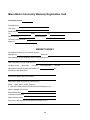
Warranty registration card
iv
Chapter 1 Safety Warning/Precautions
Explains danger and precautionary signs that apply to the handling, installation, wiring and maintenance of the
Colormetry system.
1
In addition to the following descriptions for WARNING, CAUTION and NOTE, which are
shown in each chapter in this manual, Chapter 1 includes all descriptions for WARNING,
CAUTION and NOTE, each of which is mentioned in every chapter in order to ensure safe
operation.
It is the responsibility and duty of all personnel involved in the operation, installation and
maintenance of this equipment to fully understand the WARNING, CAUTIONS, and NOTES
by which hazards are to be reduced or eliminated.
Personnel must become thoroughly familiar with all aspects of safety and equipment prior to
operation, installation and maintenance of the equipment.
This sign indicates a situation in
which incorrect handling might result
in death or injury to the operator, or
that may result in damage to
property.
WARNING
CAUTION
This sign indicates precautions for
the prevention of damage to the
equipment.
NOTE
Instructions for effective operation
and information that may become
useful are explained here.
2
Introduction
CAUTION
The Colormetry system is a hardness-leakage monitoring system that monitors the hardness of water and
issues a hardness-leakage alarm. It is not a system that remedies (effects recovery from) hardness
leakage itself.
Chapter 2
CAUTION
The customer would be required to procure the appropriate fasteners for installation of the Colormetry unit
if the supplied mounting brackets are not suitable for the location.
The customer may also need additional plumbing parts, depending on the location.
Chapter 4
NOTE
It is recommended to connect a remote signal wherever possible to prevent false detections and avoid
recovery operations.
The signal for adding water, if available, should be connected as the first priority.
If only remote regeneration signal from water softer is connected, a false detection of hardness leakage
may result from monitoring the stagnant water while the water is stopped, or a system error may occur due
to the lack of flow. A remote signal-input arrangement, as shown in examples [2]-1 and [2]-2, is
recommended.
CAUTION
If no remote signal is connected, be sure to set ("the monitoring is enabled by remote signal being turned
off") [SRte Sgl Off] mode (which is the factory setting).
CAUTION
If the remote signal setting is for “Monitoring is enabled by remote signal being turned on" [SRte Sgl On],
periodically check to verify that automatic monitoring is performed.
If no remote signal is available due to a signal problem, the monitoring process will never be initiated.
NOTE
External-alarm master contact will not be cancelled until the condition is evaluated as normal.
3
Chapter 5
CAUTION
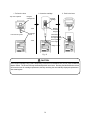
The reagent cartridge’s receptacle is plugged when the system is delivered. Never remove the plug until
installation is complete. (See Fig. 2.)
Note: If the plug is removed, the stirrer inside may roll out and get lost. An extra stirrer is attached to the
back of the front cover in case one is lost.
CAUTION
z Do not connect the drain-water pipe to other plumbing.
z Be sure to drain it to open air.
z Exercise care in keeping the drain-water pipe free of kinks.
An obstructed drain-water pipe may cause water leakage and misevaluation.
CAUTION
In case the drain-water pipe is clogged and the internal pressure builds up, the system will relieve the
pressure through either of methods (1) and (2) shown below. These methods cause drain water to leak
down through the bottom of the system. Be sure not to leave anything underneath the system.
(1) Water leaks out of the pipe connection at the bottom.
(2) Water leaks out of the internal piping.
Water will drain out of the drain holes in the bottom of the system.
CAUTION
Exercise care in keeping the tubing free of kinks.
CAUTION
Where zinc or copper plumbing is used, zinc or copper ions would dissolve and stagnate in the water. The
reagent in this system reacts with zinc and copper ions. Take the sample water as close to the water
softener as possible to avoid the effects of ions dissolving out of the plumbing.
WARNING
z
z
z
z
z
z
Use a dedicated power supply line having the specified capacity. Insufficient capacity may cause fire.
Provide a ground fault interrupter with an overcurrent-protection function to prevent electric shock.
Use a supplied wire or a larger cross section, or the wire may overheat and cause a fire.
Ground the grounding terminal to prevent electric shock and malfunction.
Be sure to clamp the wires down, or undue force exerted on them may damage the system.
The wires must have a drooping slack to prevent water leakage from running down the wires and
causing a short circuit.
CAUTION
The system starts operating as soon as the power is turned on (system is plugged in). Activate it only when
it is ready for a test run.
4
CAUTION
z If a contact representing the feeding of water is available, connect this on a highest priority. If not, set
up the start and stop time on the LCD display to avoid monitoring during water stoppage and softener
regeneration, or a system error may occur.
z Refer to Section 4-3, “Method and examples of utilizing remote signals,“ on page 24 for remote signal
functions, and connect a signal to suit the installation.
CAUTION
Turning a relay on and off generates sufficient back EMF across its coil to destroy a transistor on the
opening of the relay. Be sure to connect a surge suppresser in order to protect the transistor.
CAUTION
z Before installing a reagent cartridge, always check the manufacture date on the package. (The
cartridge life is about one year from the date of manufacture, and is used up within approximately four
months of installation.)
z When installing a reagent cartridge, push it in slowly, keeping the nozzle and check tube from hitting
the main unit.
z Be sure to push the cartridge lever back into the main unit, or the cartridge may come off and water
may leak when water pressure is applied for operation.
z Never remove the check tube from the end nozzle of the reagent cartridge. Do not touch the check
tube. Otherwise, the reagent injection volume may be affected.
WARNING
z
z
z
z
Do not use the reagent cartridge for the use other than in the Colormetry system.
Never disassemble the reagent cartridge. Reagent may splatter onto the skin or into the eyes.
Dispose of the fully intact reagent cartridge as plastic refuse.
If the reagent gets on the skin or in the eyes, rinse immediately with water.
CAUTION
Be sure to perform the checks listed in the foregoing before startup.
Chapter 6
CAUTION
Change the DSW-3 and DSW-4 settings according to the M-alkaline value of the raw water. Note that an
evaluation error may result from a setting that is incompatible with the M-alkaline value of the sample
water.
Do not change the settings other than DSW-3 and DSW-4, or the system may malfunction.
5
WARNING
Be sure to check the following before turning on the power:
[1] The power-supply voltage is correct. (24 V or 110 V transformer to 24 V)
[2] The wiring and piping are correct.
[3] The reagent cartridge is properly installed.
[4] The system’s water pressure is on and ready to feed water.
CAUTION
If the battery has been charged, be sure to review and set all items described in “Setting mode” on page 60
after exiting the status-verification test mode.
NOTE
If the “Wash Cfm F” or “Wash F” alarm occurs during a test run or initial feeding after replacing the fiber
filter – (even though the main feed-water valve is open and pressure is provided) -- take the action
shown below. This is an initial phenomenon caused by bubbles in the filter casing. It is not a system
problem.
The buzzer sounds on the alarm. Press the Manual Monitor switch to stop the buzzer, then press
the switch again to force monitoring (that is, to feed the system). If the alarm recurs, repeat this
process.
If a couple of repetitions will not stop the recurrence of an alarm, try monitoring with the
constant-flow regulator valve (black rubber plate) removed. If the removal eliminates the alarm,
restore the constant-flow regulator washer and perform another monitoring to verify that no alarm
recurs.
If the fiber filter cartridge is replaced while the power is on, the system would not automatically enter the
status-verification test mode. Press the Manual Monitor switch to monitor (to feed the water) to verify
that no alarm occurs. If the alarm recurs, repeat the process.
NOTE
[1]
[2]
If no remote signal is connected for operation, set the system up for monitoring is enabled by remote
signal being turned “off” state.
If a “now feeding water” signal is available from the site, connect the signal and set up the Colormetry
system to prevent evaluation and operational errors.
NOTE
Note that if the Up switch is used to switch the display from the installation date to the current date, and then
either the Item or Indicator switch is pressed to confirm (update) the setting, the old date (before updating)
will no longer be available.
6
Chapter 8
CAUTION
Freezing may crack the fiber filter cartridge, filter casing or monitor container inside the main unit.
CAUTION
The maximum pressure of raw water to the Colormetry system is 71 psi. Pressure beyond that may
cause water leakage due to deformations in the internal connections or gaskets. Be sure to use it under
the specified pressure.
The drain end must open into the air. Back pressure at the drain end may cause an internal water
leakage.
The main unit has a relief hole in the bottom to quickly drain away internally leaked water and prevent
short circuits.
Do not place any object underneath the installed system that may get wet in the unlikely event of internal
leakage.
Be sure to keep the feed-water and drain-water pipes free of kinks.
WARNING
(1) Do not remove the front cover from the main unit.
(2) Do not disassemble the Colormetry unit.
CAUTION
• Replace the cartridge with the power left on but only while the system is in monitor standby mode.
• Never remove the check tube attached to the nozzle of the reagent cartridge (refer to Section 3-2-2,
“External appearance of reagent cartridge,” on page 18.) Keep the fingers off the check tube too, since
doing so may affect the amount of injection.
• When installing a new cartridge, push it down slowly, being careful not to let the nozzle and check tube
hit main unit.
WARNING
Be sure to dispose of the used reagent cartridge only after completely discarding the remaining
reagent from the reagent cartridge.
CAUTION
If the reagent cartridge being used is temporarily removed for reinstallation later, do not press the Manual
Monitor switch. The buzzer will stop automatically within one minute. Pressing the Manual Monitor switch
will reset the timer for cartridge replacement, thereby rendering the automatically displayed replacement
date meaningless.
7
CAUTION
About the reagent cartridge
[1] The reagent cartridge has a definite life. Finish a cartridge within one year of its date of
manufacture, that is stated on the cartridge box. (A cartridge is used up in about four months.)
[2] Do not store cartridges for a long period of time. If they are to be stored, select a cool, dark
place.
[3] Do not break the seal on the reagent cartridge bag until the moment of installation. Doing so will
accelerate its deterioration.
[4] Do not touch the nozzle or tube of the reagent cartridge. Doing so will affect the injection level,
and in the worst case may stop monitoring.
[5] Do not use the reagent cartridge for other than the Colormetry system.
[6] Never disassemble a reagent cartridge. Reagent may splatter onto the skin or in the eyes.
[7] Dispose of the reagent cartridge, assembled intact, as plastic waste.
[8] If the reagent gets on the skin or in the eyes, immediately rinse it off with water.
CAUTION
Water spills around the main unit when replacing the fiber filter. Do not leave things underneath the unit
that should not get wet.
CAUTION
There is a constant-flow regulator washer on the end of the filter casing. If the washer is not found on the
filter casing when it is removed from the main unit, the washer may have been left behind in the filter mount
of the main unit. Remove the washer without scratching the mount.
8
Chapter 2 Before you start
Covers accessories and ordering information.
2-1
2-2
Included accessories
Information for ordering accessories
9
10
12
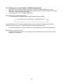
2-1 Included accessories
Check the shipped packages for the following parts and accessories, that are furnished with the CMU-124H.
• If a part or accessory is missing from the shipped package, contact your dealer.
CAUTION
The customer would be required to procure the appropriate fasteners for installation of the Colormetry unit
if the supplied mounting brackets are not suitable for the location.
The customer may also need additional plumbing parts, depending on the location.
[1]
[2]
[3]
[4]
[5]
[6]
[7]
[8]
[9]
[10]
[11]
[12]
[13]
[14]
[15]
[16]
[17]
[18]
[19]
Reagent cartridge
Filter-casing assembly
Fiber filter set
Ball valve, 1/4"B (8A)
Tube coupling 1/4” (6 mm) dia. - PT 1/4
Nipple 1/4”B (8A)
Tee 1/4”B (8A)
Mounting bracket
Screw
Cable ties
Polyethylene pipe, 1/4” (6 mm) dia.
Polyethylene pipe, 5/16” (8 mm) dia.
User’s Manual
Operator’s instruction plate
Power-transformer
Power transformer cord
Main unit
Front cover set
Spare stirrer assembly
1 ea.
1 ea.
1 ea.
1 ea.
1 ea.
2 ea.
1ea.
1 ea.
2 ea.
2 ea.
16.4 ft. (5 m)
9.8 ft (3 m)
1 copy
1 ea.
1 ea.
1 ea.
1 set
1 ea. (attached to the main unit)
1 ea. (glued to the back of the front cover)
10
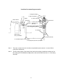
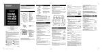
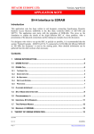
Locations for connecting accessories
1. Reagent cartridge
7. Tee
6. Nipple
Water softener
17. Main unit (Note 1)
19. Stirrer assembly
4. Ball valve
5. Tube
coupling
18. Front cover set
(attached to the
main unit)
16.
Power-transforme
r cord
Filter casing (upper) (Note 2)
Filter casing (lower) (Note 2)
10. Cable ties
Water-testing
valve, preinstalled
15. Power transformer
11. Polyethylene pipe 1/4” (6 mm) dia.
12. Polyethylene pipe 5/16” (8 mm) dia.
Note 1:
There are no parts in the main unit that are replaceable by the customer. In case of failure,
contact the manufacturer.
Note 2:
The filter casing (upper), filter casing (lower) and tube couplings (installed at the bottom of the
filter casing) are not available as single pieces, and must be ordered as item no. 3, filter-casing
assembly.
11
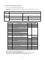
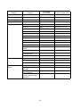
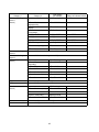
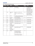
2-2 Information for ordering accessories
•
•
To order, call or fax MIURA authorized representative.
Please fill out the following form and enter the necessary quantity in the following list for ordering via
facsimile.
COMPANY
NAME
ADDRESS
Billing:
Shipping:
Attn:
FAX NO.
PHONE NO.
AUTORIZED
BY
PRINT (NAME)
DATE
SIGNATURE
PO #
Article No.
1
2
3
4
5
6
7
8
9
10
Note 1:
Note 2:
Note 3:
Note 4:
Note 5:
Specifications
Reagent cartridge CMU-H2
Filter casing assy CMU-110
Fiber filter set CHU-110
Ball valve ZS-400
Tube coupling EL6-PT1/4
Nipple 1/4B (8A)
Tee 1/4B (8A)
Mounting bracket CMU-110
Screw
Cable tie T18R
Quantity
Remarks
Note 1
Note 2
11
Polyethylene pipe ∅1/4” (∅6 mm)
12
13
14
15
16
17
18
19
20
21
22
Polyethylene pipe ∅5/16” (∅8 mm)
User’s manual
Operator’s instruction plate CMU-124H
Power transformer
Power transformer cord
Colormetry main unit CMU-124H
Front cover set CMU-110
Stirrer assembly CMU-110
Constant-flow regulator valve CMU-110
O-ring P7
O-ring S60
Inlet 16.4 ft.
(5 m)
Outlet (Note 3)
Note 4
Note 5
The fiber filter set includes a fiber filter and constant-flow regulator valve.
Item nos. 4 through 10 are provided as a set.
Item nos. 11 and 12 are provided as a set.
The main unit does not include the filter-casing assembly, reagent cartridge, etc.
The front cover set includes the front cover and stirrer assembly.
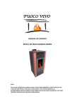
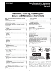
12
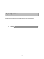
17. Main unit
1. Reagent cartridge
19. Stirrer assembly
20. Constant-flow 21. O-ring P7
regulator valve
22. O-ring S60
3. Front filter set
2. Filter-casing assembly
4. Ball valve
6. Nipple
8. Mounting bracket
5.Tube coupling
18. Front cover set
7.Tee
10. Cable ties
9. Screw
15. Power transformer
16. Power-transformer cord
11. Polyethylene pipe, 1/4” (6 mm) dia.
12. Polyethylene pipe, 5/16” (8 mm) dia.
13
Chapter 3 Specifications
Gives specifications and depicts an overview and external view of the Colormetry system.
3-1
3-2
15
16
Specifications
Overview
14
3-1 Specifications
3-1-1 General specifications
Power-supply voltage:
Power consumption:
Power-supply fluctuation:
Ambient operating temperature:
Ambient storage temperature:
Raw water temperature:
Humidity:
Raw water pressure:
AC 24 V, 50/60 Hz, single-phase
20 W (during monitoring)
±15%
41°F ~ 122°F (5°C ~ 50°C)
14°F ~ 122°F (-10°C ~ 50°C)
(must be without dew condensation in the main unit)
41°F ~ 104°F (5°C ~ 40°C)
20% min.-- 90% max. RH without ice or dew condensation
7.1 ~ 71 psi
(0.05 ~ 0.5 MPa), (0.5 ~ 5 kg/cm2)
3-1-2 Physical data
Installation method:
External dimensions:
Mass:
Indoor, wall mounted
5” (W) X 4” (L) X 20-1/4” (H)
(125 mm (W) X 100 mm (L) X 515 mm (H) )
4.6 lb (2.1 kg)
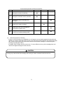
3-1-3 Monitoring capabilities
Evaluation method:
Evaluation ranges:
Via the colorimetric method
Hardness displayable in 5 ranges:
In mg/L - < 1, < 2, < 3, < 5, 5 and over
Alarm ranges:
1 mg/L and up, 2 mg/L and up , 3 mg/L and up, 5 mg/L and up
(Select one) DO NOT SET ABOVE 1 mg/L for boiler water.
Reagent cartridge replacement cycle: Approximately every 4 months
* Based on hourly monitoring, 24 hours a day
Alarm output:
Sounding of a buzzer and SPDT contact
Contact capacity: AC 24 V (use the supplied transformer to step
down from the AC 110 V to 24 V and supply 24 V to the main unit), 1
A, dry contact
Signal output during monitoring:
Open-collector output (capacity: DC 24 V, 70 mA)
Remote signal input:
AC 24 V with voltage, “NO” or “NC” contact input
3-1-4 Water-feed and drainage
Fiber filter:
Constant-flow regulator valve:
Feed-water connection diameter:
Drain-water connection diameter:
Cartridge type (standard accessory)
Material: Polyethylene
Material: EPDM
For connecting 1/4” (6 mm) external dia. pipe (supplied)
For connecting 5/16” (8 mm) external dia. pipe (supplied)
3-1-5 Accessories (refer to Chapter 2, “Before you start,” for further details.)
• Reagent cartridge
• Feed-water pipe, 1/4” (6 mm) dia., 16.4 ft. (5 m) long
• Drain-water pipe, 5/16 (8 mm) dia., 9.8 ft (3 m) long
• Filter casing and fiber filter (cartridge type)
• Ball valve and other plumbing parts
• Installation parts for wall-mounting bracket and other miscellaneous parts
• Operator’s instruction plate
15
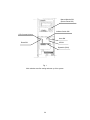
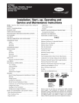
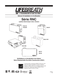
3-2 Overview
3-2-1 Colormetry system configuration
Reagent cartridge
Cartridge lever
LCD display
Manual monitor switch
(Buzzer reset switch)
Front cover
Front cover fixing screws
Filter assembly
16
mm)
mm)
mm)
mm)
mm)
mm)
mm)
mm)
mm)
mm)
17
3-2-2 External appearance of reagent cartridge
Tube
X-Ring
Tube
Reagent injection nozzle
External view of filter casing
Filter-casing assembly
O-ring
Fixed flux valve
(black rubber plate
installed on the top)
Tube joint
Filter-casing assembly
Filter casing
Filter cartridge
O-ring
18
Filter casing
(bottom)
Chapter 4 Description
Summarizes the Colormetry system and explains the monitoring methods, functions, remote signal
applications and evaluation method. It answers the question “What is the Colormetry system?”
4-1
4-2
4-3
4-4
4-5
Outline
Features
Method and examples of utilizing remote signals
About Colormetry monitor timing
Evaluation method
19
20
22
24
28
31
4-1 Outline
4-1-1 Summary of Colormetry system
The Colormetry system monitors the concentration of calcium ions and other particles in water through the
use of colormetry.
In a colormetry process the ionic calcium and other concentration in water is monitored by allowing a
reagent to react against the target ions and others, and monitoring the transmissivity of the resultant
coloration for light by a specific wavelength. An example procedure is to check for hardness leakage via the
coloration of a hardness indicator. The Colormetry system electronically automates the entire process.
Basically, the system has been developed as part of a processing system for boiler water.
Colormetry automatically and regularly implements the process of sampling water, injecting the reagent,
stirring and evaluating the result, thereby obviating the conventional manual procedure.
The system allows the detection of low-level ionic concentrations, reducing maintenance to a minimum. The
system has been designed with emphasis on reliability of monitoring results. The manually selectable
conditions--for instance, verifying monitor upon the detection of hardness leakage--prevent temporary
fluctuations from triggering alarms.
Other features include the external alarm output, DDI-compatible, self-diagnostic function, and message
display, as well as the suspension (by remote signal input) of monitoring while the water softener is
regenerating or the water feed is stopped.
Refer to 4-2, “Features” on page 22.
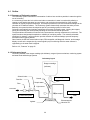
4-1-2 Colormetry layout
Colormetry consists of the reagent cartridge (the indicator), reagent injector mechanism, monitoring system
and water-feed and drainage systems.
Colormetry layout
Reagent cartridge
(Indicator)
Solenoid valve
Reagent injection
Nozzle
Fixed flux
Tube
Sample water
Filter
Light source
Feed water
Drain system
Photoreceptor
Feed-water system
Electromagnetic
induction coil
Agitator
20
Drain
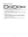
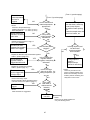
4-1-3 Operating principles of Colormetry
The Colormetry system operates as follows:
Washes and fills
a monitor
chamber with
sample water.
Injects reagent
and stirs the
sample.
Monitors light
transmitted
through the
sample.
Evaluates the
water's
hardness.
Displays the
result.
[1] Washing and filling the monitor container with sample water
A solenoid valve opens, filling the monitor container with sample water. The old sample water remaining
in the container is pushed out, and the container is washed at the same time.
[2] Injecting reagent and stirring sample water
The solenoid valve closes, and the injection pump injects the reagent into the sample water. The stirrer
coil, activated at the same time, mixes the water and reagent.
The reagent causes coloration of the sample water in accordance with the hardness components of the
water.
[3] Monitoring the sample water
A light source is activated to project light into the sample water. The light receptor electronically
monitors the light transmitted through the sample water. The intensity of the transmitted light varies,
depending on the color of the sample water. These variations are caused by light absorption in the
water, which varies with the color of the water.
[4] Evaluating the concentration and displaying the result
The concentration is evaluated from the monitoring value, and the results are indicated on the LCD
display.
21
4-2 Features
The Colormetry system has the following features:
[1]
Monitors hardness leakage automatically
•
[2]
Requires no periodic calibration
•
[3]
The monitoring process is fully automated, saving a significant amount of work by eliminating the
need for complicated manual procedures.
The system needs no cumbersome periodic calibrations.
Includes a built-in timer
(Refer to the setting instructions in Section 6-3, “About items to be set in Setting mode,” on page 60.)
•
•
[4]
Monitoring period may be set as desired (e.g., daily between 9 a.m. and 5 p.m.).
Interval for each monitoring may set as desired.
(The interval is selectable in 30-minute increments between 30 and 180 minutes.)
Detects low hardness leakage
(Refer to Section 4-5, “Evaluation method,” on page 31 for details.)
•
[5]
The evaluation ranges are 0 – 1 mg/L, 1 – 2 mg/L and over 2 mg/L.
Evaluates hardness leakage with higher accuracy
(Refer to Section 4-5, “Evaluation method,” on page 31 for details.)
•
•
[6]
The alarm set point may be set to activate either on “1 mg/L and over” or “2 mg/L and over.”
When an abnormal condition is detected, monitoring is repeated a number of times (called
abnormal-condition retries; selectable between one and three times) to prevent a temporary
fluctuation from triggering an alarm. In addition, such an abnormality must be repeated in a series
of monitoring at a preset interval for a number of times (called response (alarm) cycle; also
selectable between one and three times). When all of these monitoring results indicate an
abnormal condition, it is evaluated that hardness leakage exists and the alarm is set-off.
Indicates data on the display screen
(Refer to Chapter 7, “Digital display description,” on page 65 for details.)
•
The display indicates the abnormality, as evaluated, and the causes of major system problems.
22
[7]
Offers a self-diagnostic function
(Refer to Section 4-5-2, “How the system operates in evaluating an abnormal condition,” on page 32
for details.)
•
•
[8]
When it is evaluated that there is a leakage of hardness, the buzzer sounds. SPDT contact may
also be used to send an alarm remotely.
If a problem occurs in the system, a typical cause will be displayed in the same manner as the
hardness leakage.
Stores historical records of hardness leakage
(Refer to Section 9-3, “Verifying error records,” on page 93.)
•
[9]
The system stores the records of occurrence date and time, duration, and recovery date and time
for each of the three latest incidents of hardness leakage. These records may be utilized to
analyze the causes of hardness leakage.
Requires minimal maintenance
(For details, refer to Chapter 8, “Maintenance,” on page 69.)
•
The reagent cartridge may be replaced using a one-touch action. The reagent needs no
replacement for approximately four months in typical applications.
(Note that more frequent replacement may be necessary, depending on the application.)
[10] Compact in design, easy to install
(For details, refer to Section 5-2, “How to install the main unit,” on page 39.)
•
•
•
The main unit is installed easily on a wall.
Installation is a simple process.
It is the most compact design ever for a system of this type.
[11] About advanced features
Colormetry offers the following features:
•
Remote signal input function (refer to Section 4-3, “Method and examples of utilizing remote
signals,“ on page 24.)
Connecting the remote regeneration signal from water softener prevents a false detection that can
occur, for instance, while the water softener is regenerating, thus providing more accurate
evaluation.
•
External-alarm master contact output
The alarm’s contact output may be used to transmit a hardness-leakage alarm to a remote
location.
•
In-monitoring output (DDI compatible)
A system output is available for monitoring.
(Refer to Section 5-4, "How to wire the system,” on page 45 for functional input.)
23
4-3 Method and examples of utilizing remote signals
(For specific signal input methods, refer to Section 5-4-3, “Remote signal input,” on page 48.)
4-3-1 About remote signals
Monitoring while the water softener is regenerating may erroneously indicate hardness leakage. An attempt
to monitor with the water feed stopped would return either hardness leakage in stagnant water in the
plumbing or a system error due to a lack of flow.
Conventional hardness leakage alarm system suffered from such detection errors and required the resulting
false alarm to be manually reset. The Colormetry system provides the following two methods, which may be
used simultaneously, to avoid false alarms:
<Method No.1: Utilizing the timer function>
Monitor Start time [SStart] and Monitor stop time [SStop] settings limit the period during which monitoring
is performed. The provision helps avoid the regeneration time and off-hours of the water softener.
Example
Given the water softener settings of
Regenerating time:
11:00 p.m.
Boiler operating period: 8:00 a.m. through 5:00 p.m.
↓
Set Monitor Start time [SStart] at 8:00 a.m., and stopping time at 5:00 p.m.
(No monitoring by the Colormetry system at 11:00 p.m.)
<Method No. 2: Utilizing the remote signal feature>
Connecting the external contact with voltage may allow Colormetry monitoring only while the water
softener is turned on, or to suspend monitoring while the water softener is regenerating. (If no
voltage is available through an external contact closure, the Colormetry power supply may be utilized.)
The purpose of remote signals: To prevent a false detection while the water
softener is regenerating or the feed water is stopped.
24
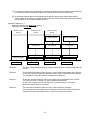
4-3-2 Detailed descriptions of remote signals
The remote signal input may be activated to enable monitoring in either of two methods - (1) the “off” state,
or (2) the “on” state. The two processing methods are selectable in the Setting mode [Set Mode]. Both
methods achieve the same objective (of preventing false detections), though they process the signal
differently.
[1]
Monitoring is enabled by remote signal being turned “Off” [SRte Sgl Off] (the factory setting)
✩ The off state of the remote signal input; (the external contact is open, giving no voltage input)
This permits scheduled monitoring at Monitor intervals [SIntvl] as preset in Setting mode [Set
Mode].
✩ Monitor interval [SIntvl] may be set in 30-minute increments up to 180 minutes. (Refer to Section
6-3, “About items to be set in Setting mode,” on page 60.)
Example: Inputting a remote regeneration signal from water softer.
Connecting a water-softener contact, if available, to the Colormetry system as a remote signal
input, which turns on (closes) during regeneration, will disable scheduled monitoring. When the
softener contact turns off (opens) at the completion of regeneration (that is, the remote signal is
off), scheduled monitoring is again enabled.
[2]
Monitoring is enabled by Remote-Signal “On” [SRte Sgl On]
The on state of the remote signal input (the external contact closes, inputting a voltage to the
Colormetry system) will enable monitoring at Monitor interval [SIntvl].
Example No. [2]-1: Inputting the feed water (to a water softener, etc.) signal
Connecting a contact, if available is being turned a water softener or the like, which turns on
(closes) while feeding water, to the Colormetry system as a remote signal input, will enable
monitoring only while feeding water. When the feed water stops or the softener regenerates, and
the contact turns off (opens), no scheduled monitoring is performed.
Example No. [2]-2: Inputting a control signal of motor valve or solenoid valve
An input signal from a motor valve or solenoid valve that controls the feed water will enable
monitoring only while the valve is open and signal is in the “on” state (contact is closed).
Example No. [2]-3: Inputting a supply tank water-level control signal
When a “Requesting feed water” signal is input from the equipment that controls the water level of
a supply tank, monitoring is performed only for the duration of the request (that is, while feeding
water).
25
NOTE
It is recommended to connect a remote signal wherever possible to prevent false detections and avoid
recovery operations.
The signal for adding water, if available, should be connected as the first priority.
If only remote regeneration signal from water softer is connected, a false detection of hardness leakage
may result from monitoring the stagnant water while the water is stopped, or a system error may occur due
to the lack of flow. A remote signal-input arrangement, as shown in examples [2]-1 and [2]-2, is
recommended.
CAUTION
If no remote signal is connected, be sure to set ("the monitoring is enabled by remote signal being turned
off") [SRte Sgl Off] mode (which is the factory setting).
26
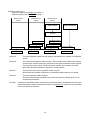
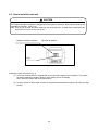
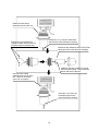
4-3-3 About the remote signal delayed time
The purpose of Remote-signal delay time [SRte Sgl dl]:
This setting determines the number of seconds the monitoring is to be delayed
following the remote signal input.
The delay function is not normally required except for preventing false evaluation, especially in the
example shown below.
Example of delay:
It is recommended that the Colormetry sample be taken from as close to the water softener outlet as
practical. (Refer to Chapter 5, “Installation,” on page 37 for details.) In the case, however, where a
sample is taken, as illustrated, off the secondary of a motor valve or the like, requiring a certain amount
of time to open fully, a wash-flow error [Wash Flow F] may occur due to insufficient sample-water
pressure when the remote signal is first connected.
(For details on setting the delay, refer to Section 6-3, “About items to be set in Setting mode,” on page
60.)
Remote signal
Motor valve
Raw water
Softened water
Colormetry system
Water softener
Sample water for
Colormetry system
Drain water from
Colormetry
To prevent such a problem, select Remote signal delay time [SRte Sgl d1] setting and ensure the
required pressure (7.1 ~ 71 psi) at the Colormetry inlet (0 ~ 30 seconds).
27
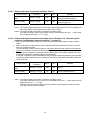
4-4 About Colormetry monitor timing
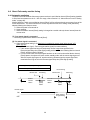
4-4-1 Automatic monitoring
The basic interval at which the Colormetry system monitors is set in Monitor interval [SLntvl] setting (settable
in 30-minute increments over the 0 ~ 180 min. range; refer to Section 6-3, “About items to be set in Setting
mode,” on page 60).
Monitor Start time, which occurs at Monitor interval [SIntvl], will be referenced to the occurrence of one of the
events listed below. The actual monitor time occurs only after the time set in Setting mode [Set Mode]
elapses following the reference event.
a. When the power is first turned on.
b. Upon resetting.
c. When the Monitor interval [SIntvl] setting is changed to a smaller value (a shorter interval) than the
current value.
[1] If no remote signal is connected
Monitoring is performed at Monitor interval [SIntvl].
[2] If a remote signal is connected
a. If the remote signal setting is for (Monitoring is enabled by remote signal being turned “off”)
[SRte Sgl Off]:
(Example of remote signal – Remote regeneration signal from water softener)
• If the remote signal has been off continuously and for longer than specified in the
Remote-signal delay time [SRte Sgl dl] setting at the monitor time following Monitor interval
[SIntvl], actual monitoring will start.
• If, on the other hand, the remote signal has been on at a monitor time after Monitor interval
[SIntvl] lapses, the system will enter monitor standby mode until the remote signal goes off.
After the remote signal goes off, actual monitoring will start when the remote signal has
remained off as long as set in the Remote-signal delay time [SRte Sgl dl] setting.
Remote-signal delay time [SRte Sgl dl]: 10 sec.
Monitor interval [SIntvl]: 60 min.
Monitor time
No monitoring
Monitoring
Monitor time
Monitoring
Monitor
interval
Monitor
interval
60min
60min
10sec
10sec
Remote signal
ON
Water softener
is regenerating
OFF
28
10sec
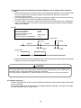
b. If the remote signal setting is for (Monitoring is enabled by remote signal being turned “on”)
[SRte Sgl On]:
(Example of remote signal – Remote regeneration signal from water softener)
• If the remote signal has been on continuously and for longer than specified in the Remote
signal delay time [SRte Sgl dl] setting at a monitor time following Monitor interval [SIntvl], actual
monitoring will start.
• If the remote signal is “off” at a monitor time following Monitor interval [SIntvl], the system
enters Monitor standby mode until the remote signal turns “on”. After the remote signal
switches “on”, actual monitoring will start when the remote signal has remained “on” as long as
set in Remote signal delay time [SRte Sgl dl] setting.
Remote-signal delay time [SRte Sgl dl]: 10 sec.
Monitor interval [SIntvl]: 60 min.
Monitor time
No monitoring
Monitoring
Monitor
interval
Monitor time
Monitoring
Monitor
interval
60min
60min
10sec
10sec
10sec
Remote signal
O
OF
For details on remote signals and remote signal delay time, refer to Section 4-3, “Method and examples of utilizing
remote signals,” on page 24.
Precautions on operation
Where a remote signal is connected and, if the remote signal is turned to disable monitoring after the
solenoid valve in the Colormetry system turns to closed state from the open state (from water
discharging from the drain tube to the stopping of drainage), the monitoring results will remain valid. The
monitoring results before the solenoid valve enters the closed state (stopping water discharge from the
drain tube) will be processed as follows:
(If the remote signal turns to disabled monitoring, the monitoring process will still be carried out to
completion.)
a. If the concentration is evaluated as being lower than the Alarm set point (setting):
The result will be displayed as usual.
b. If the concentration is evaluated as being higher than the Alarm set point (setting):
The evaluation is invalidated and a blank bar (“Result: -----“) is displayed.
29
[3] If the Monitor Start time [SStart] and Stop time [SStop] are set up (when the timer function is
used)
a. If it becomes the Monitor time after the Monitor interval [SIntvl] has elapsed, but it is not Monitor Start
time yet, the system will enter Monitor standby mode until Monitor Start time, at which point
monitoring will be performed.
b. If no remote signal is connected, monitoring will be performed at Monitor interval [SIntvl] only during
the period between Monitor Start time [SStart] and Stop time [SStop].
c. If a remote signal is connected, monitoring will be performed in the same manner as in paragraph 2
above, “If a remote signal is connected,” only during the period between Monitor Start time [SStart]
and Stop time [SStop].
Example:
Monitor start time [SStart]
Monitor stop time [SStop]
Monitor interval [SIntvl]
Monitoring is enabled by remote
signal being turned on
Remote signal delay time [SRte Sgl dl]
No monitoring
AM 8:00
PM 6:00
60 min.
[SRte Sgl ON]
10 sec
Monitor time
Monitor time
Monitoring
AM 8:00
No monitoring
AM 9:00
10sec
Remote signal
10sec
O
OF
d. If it becomes “Monitor stop time” [SStop] during the monitoring process, the system will enter “Monitor
standby” mode upon the completion of that monitoring.
CAUTION
If the remote signal setting is for “Monitoring is enabled by remote signal being turned on" [SRte Sgl On],
periodically check to verify that automatic monitoring is performed.
If no remote signal is available due to a signal problem, the monitoring process will never be initiated.
4-4-2 Manual monitoring
Press the “Manual Monitor” switch to monitor regardless of the Monitor interval, Remote signal, Monitor start
or stop time settings.
(The monitoring process will not be initiated, if the reagent cartridge is expanded. The system may initiate
the status-verification test for a system error.)
30
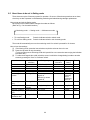
4-5 Evaluation method
The system evaluates ionic concentrations to three levels: 0 – 1 mg/L, 1 – 2 mg/L, and over 2 mg/L.
Alarm set point may be set to trigger either at 1 mg/L and up, or 2 mg/L and up.
The evaluation method is the same for the automatic and manual monitor settings.
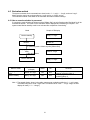
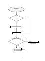
4-5-1 How a normal evaluation is processed
If a monitoring result is below the Alarm set point [SAlarm Set], as set in Setting mode [Set Mode], it will be
evaluated as normal. The result of such evaluation will be displayed and monitoring is complete. The
system enters Monitor standby mode in two minutes after completion of monitoring.
Mode
Sample LCD display
Std-by: 0-1 mg/L
Monitor standby
Monitor
Monitor On
If monitoring result < Alarm set point [SAlarm Set]
Displaying evaluation
result
After two minutes
Result: 0-1 mg/L
Monitor standby
Name of mode
Displaying evaluation
result
Monitor standby
Display indication
(example)
Std-by: 0-1 mg/L
Alarm*
Bz*
Remarks
To be displayed for two minutes
following monitoring (Note 1)
To be displayed two minutes after
Std-by: 0-1 mg/L
OFF
OFF
monitoring (Note 1)
* Alarm: External-alarm master-contact output Bz: Buzzer output
Result: 0-1 mg/L
OFF
OFF
Note 1: The sample display, shown in the table, represents an evaluation within the 0 – 1 mg/L range.
If the alarm set point is set at 2 mg/L and it is evaluated to be in the 1 – 2 mg/L range, the LCD
display will read [******** 1-2mg/L].
31
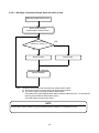
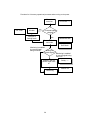
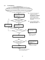
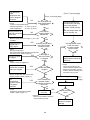
4-5-2 How the system operates in evaluating an abnormal condition
[1] If an evaluation result exceeds alarm set point [SAlarm Set] (the “1 mg/L and up,” or “2 mg/L and up”
setting), monitoring is repeated the number of times as set (between one and three times) in
Abnormal-condition retries [SAlarm Inc] setting. If all retry results have exceeded alarm set point
[SAlarm Set], only then will the monitor result will be determined as abnormal.
If, on the other hand, all retry results are lower than alarm set point [SAlarm Set] setting, the condition
will be determined to be normal and monitoring will be terminated.
[2] However, an abnormal evaluation made in step (1) alone would not trigger an abnormal-condition alarm
(that is, to sound buzzer and close the slave-remote output contact).
An abnormal-condition alarm is given only on the occurrence of an abnormal condition repeated for
Response (alarm) cycle [SAlarm Det] (selectable between one and three times) in automatic monitoring
at Monitor interval [SIntvl] (selectable between 30 and 180 minutes in 30-minute intervals) or in manually
initiated monitoring.
Monitor standby
Monitor
Num. of monitoring
performed < N1
YES
Std-by: 0-1 mg/L
Monitor On
N1:
Abnormal condition
retries [SAlarm Inc]
N2:
Response (alarm)
cycle [SAlarm Det]
NO
Num. of abnormal
condition retries
< N2
NO
Warning: > 2 mg/L
Std-by: 2 mg/L
YES
Displays evaluation
result.
Displays evaluation of
result processes
alarm
Result: 0-1 mg/L
After two minutes
After two
minutes
Monitor standby
Monitor standby
32
Std-by: 0-1 mg/L
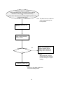
[3] If an abnormal condition occurs repeatedly in a series of automatic monitoring at Monitor interval [SIntvl],
or in manually initiated monitoring, the abnormal-condition alarm will stay on continuously.
[4] An abnormal-condition alarm is automatically terminated (the buzzer stops and the slave alarm’s
output-contact opens) when the condition is determined to be normal in automatic monitoring at Monitor
interval [SIntvl], or in manually initiated monitoring.
Example of Monitor no. 1:
Abnormal-condition retry [SAlarm Inc] setting: 2
Response cycle [SAlarm Det] setting: 2
Monitor interval
[SIntvl]
Normal condition
Monitor A
Monitor interval
[SIntvl]
Monitor interval
[SIntvl]
Abnormal-condition
alarm is set-off
Abnormal-condition
alarm is terminated
Condition is evaluated to
be abnormal
Condition is evaluated to
be abnormal
Condition is evaluated to
be abnormal
Abnormal condition
Abnormal condition
Abnormal condition
Abnormal condition
Abnormal condition
Monitor B
Monitor C
Abnormal condition
Monitor D
Monitor A:
The result is below the alarm set point (setting), and therefore the condition is deemed to be
normal.
Monitor B:
The result has exceeded the alarm set point. Since the abnormal condition retry setting is
for two times, another monitoring is performed, which again exceeded the alarm set point.
The condition in monitor B is therefore evaluated to be abnormal.
Monitor C:
As was the case with monitor B, the first two results have exceeded the alarm set point.
The result of monitor C, therefore, is also evaluated to be abnormal.
An abnormal condition has been verified twice -- in monitor B and C -- so that an
abnormal-condition alarm is now issued.
Monitor D:
The result has exceeded the alarm set point on two consecutive occasions.
The subsequent result has again been evaluated as an abnormal condition, following an
already issued abnormal-condition alarm. Therefore, the alarm will continue.
33
Example of monitor no. 2:
Abnormal condition retry [SAlarm Inc] setting: 3
Response (alarm) cycle [SAlarm Det] setting: 1
Monitor interval
[SIntvl]
Monitor interval
[SIntvl]
Monitor interval
[SIntvl]
Abnormal-condition
alarm is set-off
Abnormal-condition
alarm is terminated
Condition evaluated to be
abnormal
Abnormal condition
Normal condition
Abnormal condition
Abnormal condition
Normal condition
Monitor A
Abnormal condition
Abnormal condition
Monitor B
Monitor C
Normal condition
Monitor D
Monitor A:
The result is below the alarm set point (setting), and therefore the condition is considered
normal.
Monitor B:
The result has exceeded the alarm set point. Since the abnormal-condition retry setting is
for three times, another monitoring is performed, which again exceeded the alarm set point.
The third retry result, however, is below the alarm set point, and so passes as normal.
Monitor B is therefore evaluated to represent a normal condition.
Monitor C:
The first three results have exceeded the alarm set point.
With an abnormal condition verified once, an abnormal-condition alarm is now issued.
Monitor D:
The result is below the alarm set point.
Since the result has been evaluated to be normal, the abnormal-condition alarm is now
automatically terminated.
Remarks:
If a result has exceeded the alarm set point but a subsequent result is invalidated so that the series
of monitorings fails to satisfy the abnormal-condition retry [SAlarm Inc] requirement, the evaluation
of the series will still be abnormal.
34
4-5-2-1 Display and output on abnormal condition (Note 1)
Name of mode
Displaying evaluation
result
Monitor standby
Display indication
(a sample)
Alarm*
Bz*
Remarks
To be displayed for two minutes
following monitoring (Note 2)
To be displayed two minutes after
Std-by: > 2 mg/L
OFF
OFF
monitoring (Note 2)
* Alarm: External-alarm master-contact output Bz: Buzzer output
Result: > 2 mg/L
OFF
OFF
Note 1: The sample indications shown in the table will remain displayed from the time of evaluating an
abnormal condition until the abnormal condition alarm is issued.
Note 2: The sample display represents an evaluation exceeding 2 mg/L.
If the alarm set point is set at1 mg/L and the condition is evaluated to be in the 1 – 2 mg/L range,
the LCD display will read [******** >1 mg/L].
4-5-2-2 Display and output on abnormal evaluation (refer to Section 4-5-2, “How the system
operates in evaluating an abnormal condition,” on page 32.)
a. During an abnormal-condition alarm, the buzzer sounds and the external alarm’s master contact
closes.
b. When an abnormal-condition alarm is issued, pressing the Buzzer Reset switch on the front of the
main unit will stop the buzzer.
The external-alarm’s master contact, however, will remain closed until the condition is evaluated as
normal in an automatic monitoring at Monitor interval [SIntvl], or monitoring initiated manually.
c. Once the buzzer is stopped by pressing the Buzzer Reset switch, it will remain disabled even if the
immediately subsequent evaluation happens to be abnormal.
If, however, a condition is once evaluated as normal in automatic monitoring at Monitor interval [SIntvl]
or manually initiated monitoring, then a subsequent occurrence of the abnormal-condition alarm will
sound the buzzer.
Name of mode
Display indication
(a sample)
Displaying evaluation
result
Warning: > 2 mg/L
Monitor standby
Warning: > 2 mg/L
Alarm*
Bz*
ON
ON
Remarks
(Note 1)
This is the result of pressing, the
Buzzer reset switch once.
* Alarm: External-alarm master-contact output Bz: Buzzer output
ON
OFF
Note 1: The sample display represents an evaluation exceeding 2 mg/L.
If the alarm set point is set at 1 mg/L and it is evaluated to be in the 1 – 2 mg/L range, the LCD
display will read [******** >1 mg/L].
When the abnormal-condition alarm has been issued, the LCD display will remain the same
even after two minutes have elapsed.
35
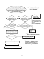
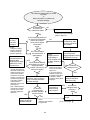
4-5-2-3 Workings of hardness leakage alarm and action to take
Hardness leakage alarm occurs.
Buzzer starts sounding.
External-alarm contact turns on.
YES
Is the Buzzer Reset
switch on? (Note 1)
NO
Buzzer sounds.
Buzzer stops.
Evaluation result is displayed.
(Monitor standby)
Note 1: The Buzzer Reset switch also functions as a manual monitor switch.
[1] The buzzer sounds on the occurrence of an abnormal condition.
[2] The buzzer stops on pressing the Buzzer Reset switch.
(The system will not automatically enter Manual monitor mode at this time. To start manual
monitor, press the Buzzer Reset switch again.)
(The LCD display will remain the same.)
NOTE
External-alarm master contact will not be cancelled until the condition is evaluated as normal.
36
Chapter 5 Installation
Shows how to install and wire the Colormetry system.
5-1
5-2
5-3
5-4
5-5
5-6
Pre-installation checklist
How to install the main unit
Plumbing
How to wire the system
Installing the reagent cartridge
Final check of installation and wiring prior to startup
37
38
39
41
45
50
52
We recommend that the user read this chapter before installation of the Colormetry for safety of operation.
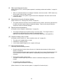
5-1 Pre-installation checklist
[1]
The raw water pressure range (both static and dynamic) must always be 7.1 to 71 psi (0.5 to 5 kg/km2).
If the pressure is outside that range, a pressurizing unit or pressure-reducing valve will be required.
[2]
Use the system with raw water in the 41 to 104°F (5 to 40°C) range. Using water outside that range
may damage the internal components.
[3]
Use the system in an ambient temperature range of 41 to 122°F (5 to 50°C). Temperatures outside this
range may cause deterioration of the reagent.
[4]
The system is designed to hang on a wall. Install it indoors, away from rain.
[5]
Avoid a location subject to direct sunlight.
[6]
Install the system in such a way that the length of feed-water line between the water softener and the
system is within 16.4 ft (5 m).
[7]
The power supply transformer is specified at AC 24 V, 20 W. A 110 ~ 120 VAC source is required near
the system.
[8]
The Polyethylene drain pipe included in the system is 9.8 ft (3 m) long, requiring a nearby drainage
trough.
[9]
Provide sufficient work space around the installed system for maintenance and operation.
38
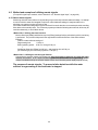
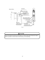
5-2 How to install the main unit
CAUTION
The reagent cartridge’s receptacle is plugged when the system is delivered. Never remove the plug until
installation is complete. (See Fig. 2.)
Note: If the plug is removed, the stirrer inside may roll out and get lost. An extra stirrer is attached to the
back of the front cover in case one is lost.
Reagent-cartridge receptacle
Top view of system
Plug
Fig. 2
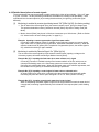
Installing the main unit (refer to Fig. 3)
(1) Screw the mounting bracket, supplied with the unit where the system is to be installed. The system
should be installed at a height to allow for easy reading of the LCD display.
Note: Mount the bracket with its rounded side up.
(2) Hook the system on the bracket mounted on the wall and screw down the bottom end of the mounting
bracket.
39
Installed system side view
Side view of system
Mounting
bracket
Rounded
corner
Screw
holes
3/16” (5.5
mm) dia.
Mounting screw
centers 8-3/4”
(224 mm)
Wall
Screw
Mounting
bracket
Bottom
plate
Screw
holes
3/16” (5.5
mm) dia.
Fig. 3
Bottom view of system
Side view of system
Cylindrical
part
Drain hole
Cylindrical part
Make sure the receptacle area is
free of deformation and burrs
Filter installation
Attaching screws for front cover
Polyethylene pipe, 5/16“ (8 mm) dia.
Fig. 3
40
Drainage trough
5-3 Plumbing
5-3-1 Drain-water pipe (refer to Fig. 4)
(1) Cut the included polyethylene pipe, 5/16” (8 mm) dia., to the length required for drainage.
(2) Insert one end of the polyethylene pipe into the tubular connection at the bottom of the system. Run
the other end into a drainage trough.
Note: The insertion of the polyethylene pipe into the tubular connection and the bottom requires some
force. Check the connection for excessive deformation or burrs before inserting the pipe.
CAUTION
z Do not connect the drain-water pipe to other plumbing.
z Be sure to drain it to open air.
z Exercise care in keeping the drain-water pipe free of kinks.
An obstructed drain-water pipe may cause water leakage and misevaluation.
CAUTION
In case the drain-water pipe is clogged and the internal pressure builds up, the system will relieve the
pressure through either of methods (1) and (2) shown below. These methods cause drain water to leak
down through the bottom of the system. Be sure not to leave anything underneath the system.
(1) Water leaks out of the pipe connection at the bottom.
(2) Water leaks out of the internal piping.
Water will drain out of the drain holes in the bottom of the system.
41
5-3-2 Feed-water line (refer to Fig. 5)
(1) Take the feed-water line off the outlet side of the water softener. (The feed-water line connection may
be made from the water softener’s water sampling valve.)
(2) Pre-cut the included polyethylene pipe, 1/4” (6 mm) dia., to the length required for the installation, and
firmly insert the end into the tube coupling.
(3) Assemble the filter according to the following procedure (refer to Fig. 6):
[1] Take the filter-casing assembly out of the bag. Remove the tape from the end.
Note: There is a constant-flow regulator valve installed at the end of the casing. Be careful not
lose the washer during installation.
A spare constant-flow regulator washer is attached to the filter-cartridge box. The spare
may be used to replace a lost washer.
[2] The filter casing comes apart into two sections. To take them apart, rotate the top and bottom
sections in the direction of arrow.
[3] Remove the filter cartridge from the box (bag). Align the outlet end of the cartridge in the center of
the top casing. Insert the cartridge all the way, then firmly tighten the bottom casing.
(4) Insert the polyethylene pipe firmly into the tube coupling on the bottom casing.
(5) Screw the filter casing into the bottom plate on the system. There is no need for tightening it hard,
since the O-ring at the end of filter casing will provide a good seal.
(6) Use the included cable ties to bundle the 1/4” (6 mm) dia. Polyethylene tube to the 5/16” (8 mm) dia.
polyethylene pipe.
(Doing so will prevent the 5/16” (8 mm) tube from dropping out of the system if external force is exerted
upon it.)
Bundle them together about 6 to 8 inches (150 to 200 mm) away from the bottom of the filter casing. If
it is tied too close to the filter casing, undue prying force may be exerted on the tube coupling and
cause leakage.
CAUTION
Exercise care in keeping the tubing free of kinks.
42
Water softener
Ball valve
Additional plumbing
Tube coupling
1/4 (6) dia.
Polyethylene tube
Filter casing (bottom)
Tube coupling
Cable tie
Existing
water-sampling
5/16 (8) dia.
Polyethylene tube
Fig. 5
CAUTION
Where zinc or copper plumbing is used, zinc or copper ions would dissolve and stagnate in the water. The
reagent in this system reacts with zinc and copper ions. Take the sample water as close to the water
softener as possible to avoid the effects of ions dissolving out of the plumbing.
43
Filter casing Assy
Tape
Constant-flow regulator
washer (the black rubber
plate fitted into the end.)
Outlet
Filter casing (bottom)
Filter cartridge
Tube coupling
1/4 (6) dia.
Polyethylene tube
Filter casing (top)
Front view of system
Before screwing in the filter, be
sure that the constant-flow
regulator washer is inserted.
Screw it into the bottom plate
with the 1/4” (6 mm)
polyethylene tube attached.
Bundle the tube together with a
cable tie.
Tie about 6 to 8 inches (150 to
200 mm) away from the bottom
of the filter casing.
Fig. 6
44
5-4 How to wire the system
5-4-1 Routing the wires (Refer to Fig. 7)
(1) Loosen the screw at the bottom of the system and remove the front cover.
(2) Pass the wires through the wire holder and wire hole in the bottom plate. Gather and connect the wires
to the terminal block on the circuit board.
(3) Provide a drooping slack in the wires, and clamp them down.
WARNING
z
z
z
z
z
z
Use a dedicated power supply line having the specified capacity. Insufficient capacity may cause fire.
Provide a ground fault interrupter with an overcurrent-protection function to prevent electric shock.
Use a supplied wire or a larger cross section, or the wire may overheat and cause a fire.
Ground the grounding terminal to prevent electric shock and malfunction.
Be sure to clamp the wires down, or undue force exerted on them may damage the system.
The wires must have a drooping slack to prevent water leakage from running down the wires and
causing a short circuit.
Front view of system
Terminal block (refer to Fig. 8)
(Connect wiring as required by
the site.)
In-monitoring output
terminal
Wiring window
Bottom view of system
Wire holder
Front cover’s
fixing screw
Wiring hole
Wire holder
Fig. 7
45
Clamp the wires
Provide a drooping
slack for the wire
CAUTION
The system starts operating as soon as the power is turned on (system is plugged in). Activate it only when
it is ready for a test run.
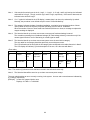
1
2
External-alarm
master output
AC 24V, 1A
3
4
5
Remote
signal input
AC 24V
6
7
FG
(Ground)
8
Power supply (power
transformer)
AC 24V, 50/60Hz
(Connect the included
power transformer to
terminal No. 7 and 8.)
NOTE: OUR APOLOGIES – WE ARE REPRINTING
2001 Model HAS 9 PINS – SPARE PIN AFTER 5 – THEN NEXT PIN IS ONE SIDE OF TRANSFORMER, NEXT
PIN IS GROUND AND LAST PIN IS OTHER SIDE OF TRANSFORMER . IF YOU REQUIRE CLARIFICATION,
PLEASE FAX SERVICE DPARTMENT AT 519-758-8111
Transistor
D1 D2 FG M+ MNot used
In-monitoring output (DDI-Compatible)
Fig. 8
46
5-4-2 External-alarm master contact output
z
This is a SPDT contact. Connect it as required for installation.
Contact capacity: AC 24 V, 1 Amp.
Note: If an inductive load such as a relay is used, connect a spark suppresser (CR or a varister) across
it.
z
A boiler equipped with a XJ1 controller (model LX, EX or WX series) can be configured as shown in Fig.
9 to indicate a caution, “Check softener” message on the boiler display in case of an abnormal
condition alarm or a Colormetry system error.
Terminal block in Colormetry
1
2
3
4
Be sure to remove the
shorting jumper
78 79 80 81 82 83
Water-softener monitoring circuit
Terminal block in XJ1 boiler
Fig. 9
47
(Typical boiler
terminal strip
numbers.
See individual boiler
schematic drawing.)
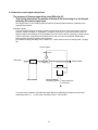
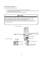
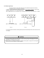
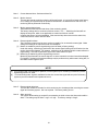
5-4-3 Remote signal input
Connecting a AC 24 V contact with voltage (AC 24 V) enables the system to be remotely
controlled for starting and stopping of monitoring.
In addition, a remote signal may be utilized in either mode -- the “on” state or “off” state - to start or stop
monitoring. (Either the “a” or “b” contact may be used.)
Wire a voltage input (AC 24 V) as shown in Fig. 10, and a nonvoltage input as described in Fig. 11, below.
3
4
5
6
Remote signal
(“NO” or “NC” contact with voltage)
3
4
5
6
7
8
Remote signal
(“NO” or “NC” contact without voltage)
AC24V
Fig. 11
Fig. 10
If no remote signal is connected, monitoring will be performed automatically at the monitor interval set in the
LCD display.
CAUTION
z If a contact representing the feeding of water is available, connect this on a highest priority. If not, set
up the start and stop time on the LCD display to avoid monitoring during water stoppage and softener
regeneration, or a system error may occur.
z Refer to Section 4-3, “Method and examples of utilizing remote signals,“ on page 24 for remote signal
functions, and connect a signal to suit the installation.
48
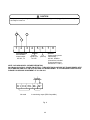
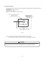
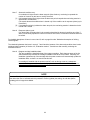
5-4-4 In-monitoring output
This is an open-collector output that turns on only during the monitoring process to indicate that monitoring
is in progress.
External DC power supply is required.
Capacity: DC 24 V, 70 mA.
Refer to Fig. 12 to connect the output as required.
Note: A built-in diode-type DC
relay (24 V, max.)
FG M+ M-
DC power source (24 V, max.)
Fig. 12
Note: A DC relay with a coil-type surge-suppressing diode is recommended.
If an ordinary type DC relay is to be used, connect a diode in parallel with the relay.
CAUTION
Turning a relay on and off generates sufficient back EMF across its coil to destroy a transistor on the
opening of the relay. Be sure to connect a surge suppresser in order to protect the transistor.
49
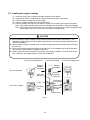
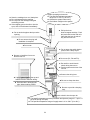
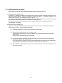
5-5 Installing the reagent cartridge
(1)
(2)
(3)
(4)
(5)
Remove the plug from the reagent cartridge receptacle in the system.
Completely pull out the cartridge lever, which is located at the front of the system.
Take the reagent cartridge out of its box (bag).
Insert the reagent cartridge into the receptacle firmly.
Push the cartridge lever back in and check to see that it is completely returned into the system.
Note: If the reagent cartridge lifts up when the cartridge lever is pushed in, reinsert the cartridge.
Note: If the bottom of the horizontal line in the cartridge’s surface design is not lined up approximately
with the edge of the cover on the main unit, insert the cartridge again.
CAUTION
z Before installing a reagent cartridge, always check the manufacture date on the package. (The
cartridge life is about one year from the date of manufacture, and is used up within approximately four
months of installation.)
z When installing a reagent cartridge, push it in slowly, keeping the nozzle and check tube from hitting
the main unit.
z Be sure to push the cartridge lever back into the main unit, or the cartridge may come off and water
may leak when water pressure is applied for operation.
z Never remove the check tube from the end nozzle of the reagent cartridge. Do not touch the check
tube. Otherwise, the reagent injection volume may be affected.
2. Insert the cartridge
1. Pull out the cartridge lever
Reagent
cartridge
receptacle
Reagent
cartridge
Tube (rear
opening)
Bottom of
horizontal
design line
3. Push the cartridge lever
Top view of system
The bottom of
the horizontal
line
approximately
lines up with
the edge
Tube
Front view of system
Cartridge
lever
Edge of cover
Fig. 13
50
WARNING
z
z
z
z
Do not use the reagent cartridge for the use other than in the Colormetry system.
Never disassemble the reagent cartridge. Reagent may splatter onto the skin or into the eyes.
Dispose of the fully intact reagent cartridge as plastic refuse.
If the reagent gets on the skin or in the eyes, rinse immediately with water.
51
5-6 Final check of installation and wiring prior to startup
Checking installation conditions
(1) The Colormetry system is designed for indoor installation only. Is the installation free of rain water and
out of direct sunlight?
(2) Is the operating environment appropriate (water pressure, water temperature and ambient
temperature)?
(3) Is the system firmly attached to a wall surface, etc.?
(4) Is the reagent cartridge correctly installed and the cartridge lever positively locked in?
(5) Is the filter assembly installed correctly?
[1] Is the fiber filter cartridge properly set into the filter casing?
[2] Is the constant-flow regulator washer (a black rubber plate) installed at the end of the filter casing?
[3] Are the top and bottom halves of the filter casing tightly assembled together?
[4] Is the filter assembly correctly mounted onto the main unit?
(6) Is there anything under the system that should not get wet?
(7) Is the system free of excessive scratches or dirt?
Checking the wiring
(1) The system is specified for AC 24 V at 20 W. Is the accessory transformer for converting AC 110 volt to
24 volts installed? Is the power-supply line correct (voltage, capacity and wire diameter)?
(2) Is a ground fault interrupter with overcurrent protection installed in the power-supply line?
(3) Is the system’s grounding terminal connected?
(4) Are the wiring connections correct?
(5) Is the wiring provided with a drooping loop just ahead of clamping point?
(6) Have the terminals been retightened to be sure?
Checking the plumbing
(1) Are the feed-water and drain-water pipe connections correctly made?
(2) Are the feed-water and drain-water pipes free of kinks or flattening?
(3) Is the drain-water pipe open to the air and independent of other plumbing?
(4) With the water pressure turned on, are there any leaks in the connections?
CAUTION
Be sure to perform the checks listed in the foregoing before startup.
52
System operating environment
z The specified ambient temperature
range is 41 to 104°F (5 to 40°C).
z Operate the system indoors only.
z Avoid direct sunlight on the system.
z Store the cartridges in a cool, dark place.
z Do not disassemble the cartridge.
z Do not pull on the cartridge during the
monitoring process.
z If the reagent gets on the skin or into the
eyes, rinse it off with water immediately.
z Pull up the lever.
Insert a reagent cartridge. Push
the lever back into the main unit.
Verify that the lever is pushed
fully into the main unit.
z Do not touch the pipe at the tip or at the
opening.
z Do not remove the plug until
installation is complete.
z Do not use.
z Do not press the switch hard or
press it with a sharp object.
z Be sure to install the front cover
after the test run.
z Do not use (D1, D2 and FG).
z Be careful to avoid electric
shock during the test run.
z Set the system at the time of the
test run.
z Connect the wiring here.
z Lightly tighten together the top and
bottom halves of the filter casing.
z Be sure to clamp the wires.
z Exercise care in arranging the
pipe, without making it bend.
z Be sure to provide a drooping
loop.
z Be sure to drain it into the open air.
z The specified raw water pressure (both static and dynamic) range is 7.1 psi to 71
psi (0.05 through 0.5 Mpa).
z The specified temperature range of supply water is 41 to 104°F (5 to 40°C).
53
Chapter 6 Settings and Start up
Guides you through set up and test run. Perform the setup and start the system by following the instructions
given in items 6-1 through 6-5.
6-1
6-2
6-3
6-4
6-5
Setting up the system
Checking the system operation and settings
About items to be set in Setting mode
Verifying monitor operation
Verifying the issuance of an abnormal-condition alarm
54
55
57
60
63
64
6-1 Setting up the system
The items described below must be set in order for the system to operate properly.
The system will operate as set at the factory. However, change the settings as required for each
installation.
Setting the DIP switch
Before turning the power on, open the front cover in the main unit and check the Dip-switch setting. Change
the setting as required. (Refer to Fig. 1)
2
3
4
5
6
7
8
1
Set the DIP switch (SW2) on the main board to set the following items:
OF
(Note) 1⋅⋅⋅ DSW-1
(1) Selecting the type of monitoring
DSW-1
OFF
DSW-2
OFF
DSW-5
ON
DSW-1, -2 and -5 need no changes, as they have been set at the factory. Simply verify the settings
shown in the table above.
If the settings are correct, a “HARDNESS MONITOR” message is displayed when the power is turned
on.
If the settings are incorrect, a “DIP SW Err” message will be indicated when the power is turned on or
when initializing at a reset.
(2) Setting for M-alkaline value
DSW-3
OFF
ON
OFF
ON
DSW-4
OFF
OFF
ON
ON
M-alkaline value
Under 60 mg/L
60 mg/L and over, but under 120 mg/L
120 mg/L and over, but under 300 mg/L
300 mg/L and over, but under 500 mg/L
Remarks
Factory setting
CAUTION
Change the DSW-3 and DSW-4 settings according to the M-alkaline value of the raw water. Note that an
evaluation error may result from a setting that is incompatible with the M-alkaline value of the sample
water.
Do not change the settings other than DSW-3 and DSW-4, or the system may malfunction.
55
Manual Monitor SW
(Buzzer Reset SW)
Indicator Switch SW
LCD Contrast Volume
Items SW
UP SW
Reset SW
Dipswitch (SW2)
Fig. 1
Main switches used for setting and start up of the system
56
6-2 Checking the system operation and settings
WARNING
Be sure to check the following before turning on the power:
[1] The power-supply voltage is correct. (24 V or 110 V transformer to 24 V)
[2] The wiring and piping are correct.
[3] The reagent cartridge is properly installed.
[4] The system’s water pressure is on and ready to feed water.
6-2-1 Turning the power on
Turn on the power. Some units have the data-memory backup battery already charged, while others do not.
Check the system accordingly.
(1) If the data-memory backup battery has been charged by the time the power is turned on, or when
reinitialized from a reset:
[1] Check to verify that a “CPUver....” message is displayed when the power is first turned on.
[2] Next, verify that a “MHardness Mon” message is displayed.
[3] The system then enters the status-verification test mode.
(2) If the data-memory backup battery has not been charged when the power is turned on, or when
reinitialized after executing an complete reset.
[1] Check to see that a “CPUver...” message is displayed when the power is first turned on.
[2] Verify that an “All Clear” message is displayed.
[3] The mode changes to Setting mode.
Refer to Section 6-3, “About items to be set in Setting mode,” on page 60 to set the items. Be sure
to set the current date, time and cartridge-installation date.
[4] When all settings have been made, press the Indicator switch.
[5] Verify that a “MHardness Mon” message is displayed.
[6]
The mode automatically changes to the status-verification test mode to verify correct system
operation.
(3) If the LCD display is hard to read, adjust it with the “Contrast Adjust” potentiometer.
CAUTION
If the battery has been charged, be sure to review and set all items described in “Setting mode” on page 60
after exiting the status-verification test mode.
57
Flowchart for Colormetry operational processes when turning on the power
Power is
turned on
ALL Clear
All clear
NO
CPUverDE*****
Is internal battery
charged?
Changes to
Setting mode
YES
MHardness Mon
Status-verification
test mode
Self Check
Monitoring is enabled
by remote signal
Setting for
being turned off
remote signal? Monitoring is enabled
by remote signal being
turned on
Stand by until the
remote signal turns
on
Std-by: ----
Monitor On
Monitoring
58
6-2-2 Status-verification test mode
This is the mode that automatically tests the system for proper operation.
• If the system is working correctly, the status verification is complete in about two minutes. At its
completion the buzzer sounds and monitoring starts.
Note: If the remote signal setting is for “Monitoring is enabled by remote signal being turned on,” the
system will stand by for monitoring as of the completion of the status verification until the remote
signal turns on.
• If a normal condition is not verified, the status verification (self-check) is repeated. The status verification
will be repeated up to five times until the system checks out as normal. Repetition will require some time.
Wait until the final results are displayed.
• During a repeated self-check, a “Self-Check Retry” indication is added to the displayed status message.
• If repeated retries fail to verify normal conditions, the buzzer will sound and an error message will be
indicated in the LCD display. The self-check stops and the system will then enter system error standby
(self-diagnostic error) mode.
NOTE
If the “Wash Cfm F” or “Wash F” alarm occurs during a test run or initial feeding after replacing the fiber
filter – (even though the main feed-water valve is open and pressure is provided) -- take the action
shown below. This is an initial phenomenon caused by bubbles in the filter casing. It is not a system
problem.
The buzzer sounds on the alarm. Press the Manual Monitor switch to stop the buzzer, then press
the switch again to force monitoring (that is, to feed the system). If the alarm recurs, repeat this
process.
If a couple of repetitions will not stop the recurrence of an alarm, try monitoring with the
constant-flow regulator valve (black rubber plate) removed. If the removal eliminates the alarm,
restore the constant-flow regulator washer and perform another monitoring to verify that no alarm
recurs.
If the fiber filter cartridge is replaced while the power is on, the system would not automatically enter the
status-verification test mode. Press the Manual Monitor switch to monitor (to feed the water) to verify
that no alarm occurs. If the alarm recurs, repeat the process.
59
6-3 About items to be set in Setting mode
These items set up the Colormetry system for operation. Be sure to follow these procedures to set them,
since they are also important in understanding monitoring and administering cartridge replacement.
How to enter and exit the Setting mode
Each press of the indicator switch changes the modes as follows:
(Refer to Fig. 1 for the switch location.)
Monitoring mode → Setting mode → Maintenance mode
• To enter Setting mode:
• To exit from Setting mode:
Press the indicator switch to switch mode.
Press the indicator switch to exit the setting mode.
The mode will automatically return to the monitoring mode if no switch is pressed for 10 minutes.
How to input item settings
[1] In the Setting mode, press the Item switch as required to select an item to be set.
[2] Press the Up switch to vary the setting.
(To vary a setting over a wide range, hold the Up switch for over a second to start varying the indication
at a faster rate.)
[3] To make the changed valve valid, switch the screen in which the change/setting is made to another
screen by pressing the "Item" or “Indicator” switch.
Item
Current date
Current time
Monitor interval
Monitor start time
Monitor stop time
Remote signal
function
Remote signal
delay
Alarm set point
Abnormal condition
Response (alarm)
cycle
Reagent cartridge
installation date
Sample
indication
SDate 06/23/99
STime 15:28
SIntvl 060min
SStart 08:30
SStop 20:30
SRet Sgl Off
SRet Sgl Dl 10s
Setting range
Factory
setting
Remark
97/01/01 ~ 20/12/31
00:00 ~ 23:59
000 min ~ 180 min
00:00 ~ 23:59, 24:-00:00 ~ 23:59
Monitor by remote
signal on
Monitor by remote
signal off
1
1
30 min
1
1
0 sec ~ 30 sec
1 sec
0 sec
Note 5
1 mg/L
2 mg/L
Note 6
1
1
2 times
2 times
Note 7
Note 8
SAlarm Set
1 mg/L, 2 mg/L
2.0mg/L
SAlarm Inc No:2 1 to 3 time
SAlarm Det No:2 1 to 3 times
SC Rpl 06/23/99
Setting
increment
97/01/1 ~ 20/12/31
60
060 min
24:-Stop
Monitoring is
enabled by
remote
signal being
turned off
Note 1
Note 1
Note 2
Note 3
Note 3
Note 4
Note 9
Note 1.
Current date and time: Set these without fail.
Note 2.
Monitor interval:
This sets the interval at which monitoring will be performed. It is set at 60 minutes at the factory,
so no change is required except for special circumstances. Be aware that if a 000 min is set,
monitoring will be performed continuously.
Note 3.
Monitor start and stop times:
These determine the start and end times of the monitoring period.
The factory settings are for continuous 24-hour monitor, “24: --.“ Switching the items will not
display the stop time, which is not applicable to continuous 24-hour monitor.
In setting the times to suit the installation, if the start and stop times are set to the same time,
continuous 24-hour monitor will take effect.
Note 4.
Remote signal functions:
The Colormetry system may be set to monitor or stand by for an external remote signal. Make
settings according to the requirements at the installation.
Monitor is enabled by remote signal being turned off state (a factory setting)
Under this setting, monitoring is performed if the remote signal is being turned off at the time the
monitor interval has elapsed. For instance, monitoring can be inhibited while the water softener is
regenerating, if a remote regeneration signal from water softener is input.
Monitoring is enabled by remote signal being turned on
Monitoring is performed if the remote signal is on at the moment the monitor interval has elapsed.
For instance, monitoring for hardness leakage may be performed only while water is being fed, if a
feed water-control signal is input.
[1]
[2]
NOTE
[1]
[2]
If no remote signal is connected for operation, set the system up for monitoring is enabled by remote
signal being turned “off” state.
If a “now feeding water” signal is available from the site, connect the signal and set up the Colormetry
system to prevent evaluation and operational errors.
Note 5.
Remote signal delay time:
This sets the number of seconds for which monitoring is to be delayed after receiving the remote
signal at Colormetry system. Set it as required. The factory setting is zero.
Note 6.
Alarm set point:
The system allows setting up a specific concentration at which to issue the Abnormal-condition
alarm. The setting may be either 1 mg/L or 2 mg/L. The factory setting is 2 mg/L.
61
Note 7.
[1]
[2]
Note 8.
Abnormal-condition retry:
If a evaluation is higher than the alarm set point (Note 6 above), monitoring is repeated the
number of times set by this item to reverify the result.
If all repeated monitoring is higher than the alarm set point, that particular monitoring session is
determined to be abnormal.
(The actual abnormal-condition alarm is issued only if the condition set in response (alarm) cycle
is satisfied.)
If a repeated monitoring is below the alarm set point, the monitoring session is determined to be
normal and is closed.
Response (alarm) cycle:
If an abnormality, as determined in the procedure described in abnormal-condition retry (Note 7
above) continuously repeats the number of times set in this item, an abnormal-condition alarm will
be issued.
For detailed descriptions of items in notes 4 and 5, refer to page 24 under “Method and examples of utilizing
remote signals.”
The relationship between the items in notes 2, 7 and 8 and the issuance of the abnormal-condition alarm is also
explained (with illustration) in Section 4-5, “Evaluation method.” Set this item after carefully reviewing the
evaluation method.
Note 9.
Reagent cartridge installation date:
The item updates the installation date of the reagent cartridge. Each alternate press of the Up
switch alternatively indicates the cartridge installation date or the current date. Normally, the
installation (replacement) of the cartridge with the power turned on will automatically update the
installation date, so there is no need to set this item.
If a cartridge is installed with the power turned off, such as during a test run, subsequent
restoration of the power will not automatically update the installation date. If the date must be
updated, press the Up switch to update it.
NOTE
Note that if the Up switch is used to switch the display from the installation date to the current date, and
then either the Item or Indicator switch is pressed to confirm (update) the setting, the old date (before
updating) will no longer be available.
62
6-4 Verifying monitor operation
Verify whether monitoring is being performed properly after all items have been set.
Checking the monitor operation (1)
A “Monitor On” message is indicated in the display during monitor operation, regardless of whether it is an
automatic or manual session. When the monitoring is complete, a “Result: ****” message is indicated. Two
minutes after monitoring, the message changes to “Std-by:********.”
First, verify that the system is under pressure and ready to feed water. Check for correct monitor operation
by pressing the Manual Monitor switch to initiate the monitoring process.
If an error occurs during the monitoring process, the system will assume the system error standby
(self-diagnostic error mode).
Checking the monitor operation (2)
Verify that monitoring is being performed properly at the monitor interval or controlled correctly via the
remote signal. To do so, use the following procedure:
[1]
Verify that the system is under pressure and ready to feed water.
[2]
Set the monitor interval at 000 min. in Setting mode.
This setting allows continuous monitoring between the monitor start and stop times as set in
Setting mode.
Set the monitor start and stop times as desired.
[3]
If no remote signal is connected, verify that the system will continuously perform monitoring
between the monitor start and stop times.
If a remote signal is connected, check to see that monitoring is performed on the remote signal
being turned on or off during the period between monitor start and stop times.
[4]
After checking monitor operation, restore the monitor interval and monitor start and stop times to
their original settings.
63
6-5 Verifying the issuance of an abnormal-condition alarm
Deliberately create an abnormal condition and verify the sounding of the buzzer operation or the closure of
the external alarm’s master contact output. Use the following procedure for verification:
[1]
Turn the no.1 switch (DSW-1) in the DIP switch to “On.”
Refer to “Setting the DIP switch” on page 55.
[2]
Press the Reset switch to reinitialize the system.
Refer to Section 9-4, “How to reset,” on page 97.
[3]
Verify that a “DIP SW Err” message is indicated in the LCD display, the buzzer sounds and the
external alarm’s master contact closes.
[4]
After so verifying, return the no. 1 switch (DSW-1) to the “Off” position and press the Reset switch
to reinitialize the system.
[5]
Since an abnormality has been caused deliberately, an error will be recorded in the system’s error
record. (Refer to Section 9-3, “Verifying error records (How to use Maintenance mode),” on page
93.)
If such a test record is undesirable, it may be deleted through the All Reset procedure (refer to
Section 9-4, “How to reset,” on page 97). This procedure, however, will delete all new settings and
restore the factory settings. Select new settings again in Setting mode.
64
Chapter 7 Digital display description
Explains the messages displayed in all three modes.
7-1
7-2
7-3
66
67
68
Monitoring Mode
Set Mode
Maintenance Mode
65
7-1 Monitoring Mode
1
2
3
4
5
6
7
8
9
10
11
12
13
14
15
16
17
18
19
20
21
22
23
24
25
26
27
28
29
Display
CPUverDE111012
Hardness Monitor
Pump Start Cfm
Self Check
Self Check Retry
Std-by: ---Std-by: 0-1mg/L
Std-by: 1-2mg/L
Std-by: >2mg/L
Monitor On
Monitor On Retry
Result: 0-1mg/L
Std-by: 0-1mg/L
Result: 1-2mg/L
Std-by: 1-2mg/L
Result: >2mg/L
Std-by: >2mg/L
Warning: >1mg/L
Warning: >2mg/L
Cartridge OFF
Cartridge OFF F
Pump Cfm F
Pump F
Wash F
Wash Cfm F
Injection Cfm F
Injection F
Wash Flow F
Photo Rpt F
SW ON Cfm
Dip SW Err
New Cartridge
Description
CPU version
Hardness monitor
During verification of the pump in its home position
Self check
Self check retry
Waiting for monitoring stage
Monitor stand-by: 1mg/L or less
Monitor stand-by: Between 1mg/L and 2mg/L
Monitor stand-by: 2mg/L or more
Monitoring ionic concentration(hardness)
Monitor on retry
Result: 1mg/L or less
Monitor stand-by: 1mg/L or less
Result: Between 1mg/L and 2mg/L
Monitor stand-by: Between 1mg/L and 2mg/L
Result: 2mg/L or more
Monitor stand-by: 2mg/L or more
Hardness leakage detected: 1mg/L or more
Hardness leakage detected: 2mg/L or more
Cartridge disconnected
Cartridge disconnected fault
Pump confirmation error
Reagent injection pump fault
Insufficient pre-wash
Faulty confirmation on pre-wash
Faulty confirmation on reagent injection
Incomplete reagent injection
Insufficient water flow for wash
Photorecepter fault
Switch ON confirmed after cartridge replacement
Dip switch error
Need cartridge replacement
66
7-2 Set Mode
1
2
3
4
5
6
7
8
9
10
11
12
Display
SDate 06/23/99
STime 15:28
SIntvl 060min
SStart 08:30
SStop 20:30
SRet Sgl Off
SRet Sgl On
SRet Sgl Dl 10s
SAlarm Set2.0mg/L
SAlarm Inc No:2
SAlarm Inc No:3
SAlarm Det No:3
SC Rpl 06/23/99
Description
S Date (m/d/y) 06/23/99
S Time 15:28
S Monitor interval 60 min
S Start time 08:30
S Finish time 20:30
S Monitor by remote signal off
S Monitor by remote signal on
S Remote signal time delay
S Alarm set at 2mg/L
S 2 consecutive incidents set alarm off
S 3 consecutive incidents set alarm off
S 2nd leakage detection set alarm off
S Cartridge replacement date(m/d/y)
S: Indicate Set Mode
67
7-3 Maintenance Mode
18
19
20
21
22
23
24
25
Display
MHardness 2.0mg/L
MCPUver DE111012
M06/23/99 15:28
MHardness Mon
MIN-OUT Mode *
MOUT1 1111 1111
MOUT2 1111 1111
MIN1 1111 1111
MIN2 1111 1111
MAD FF FF <FIG--MAD (Thmsta): FF
MAD(R): FF <FIG--MAD(-): 00 00
MAD(G): FF <FIG--MWash Pd 9.99S
MMAlkal < 60mg/L
MMAlkal < 120mg/L
MMAlkal < 300mg/L
MMAlkal <500mg/L
MWL: <TBL--MWL: S
MOp Stus: <FIG--MAlarm Content *
MError1: 11111111
Merror2: 11111111
MCartridge Dta *
MC Exc 06/23/99
MC Hrs 999999
MRgt Inj Fqc9999
26
27
28
29
30
31
32
33
34
MLeakage Log1 *
MDate 06/23/99
MTime 15:28
MEvl Stg Conc: 2
MLeakage Min9999
MRset 06/23/99
MRset Time 15:28
MStm Fault Log1*
MBlk Out Log1 *
1
2
3
4
5
6
7
8
9
10
11
12
13
14
15
16
17
Description
M Result hardness 2.0mg/L
M CPU version
M Date(m/d/y) & time
M Hardness monitor
M Input-output mode
M Output1 1111 1111
M Output2 1111 1111
M Input1 1111 1111
M Input2 1111 1111
M AD FF FF FF
M AD Thermista: FF FF
M AD(R): FF FF
M AD(-): 00 00
M AD(G): FF FF
M Pre Wash period 9.99 secoud
M Set M-alkalinity at 60mg/L or less
M Set M-alkalinity at 60mg/L to 120mg/L
M Set M-alkalinity at 120mg/L to 300mg/L
M Set M-alkalinity at 300mg/L to 500mg/L
M select from LED wavelength table: L
M select from LED wavelength table: S
M Operation status: FF
M Alarm description
M Error table 1: 11111111
M Error table 2: 11111111
M Cartridge data
M Cartridge replacement data(m/d/y)
M Cartridge used hours since replacement: 999999
M Reagent injection frequency since cartridge replacement:
9999
M Hardness leakage record 1
M Date of Hardness leakage(m/d/y) 06/23/99
M Time of Hardness leakage 15:28
M Evaluation standard at concentration of 2
M Total leakage minute: 9999min.
M Date of reset (m/d/y): 06/23/99
M Time of reset: 15:28
M System error record 1
M black out record 1
M: Indicate Maintenance Mode
Maintenance Mode display can be changed by pressing the “Items” switch.
In the event a * mark appears, mode/display can be changed by pressing the “UP” switch.
68
Chapter 8 Maintenance
Explains daily maintenance the Colormetry system and how to replace the reagent cartridge, fiber filter
cartridge and constant-flow regulator valve.
8-1
8-2
8-3
8-4
Routine care
General information
Replacing the reagent cartridge
Replacing fiber filter cartridge and constant-flow regulator valve
69
70
72
73
77
8-1 Routine care
(1) Daily inspection items
[1] Verifying the results of monitoring (weekly)
Use an ordinary hardness-indicator reagent to check for evaluation errors due to a possible system
malfunction. Record the results.
An ordinary hardness-indicator reagent may be too low in sensitivity to compare the monitoring of
minute hardness leakage against the Colormetry system. If the monitoring results of the two are
obviously different, the system may have developed a problem.
Note: Use a low-range hardness indicator for this comparison (gpg range is not suitable).
[2]
Verifying the results of automatic monitoring (weekly)
Check for proper automatic monitoring.
Where a remote signal is connected, but does not turn on due to a problem, the system will not enter
the monitor status.
[3]
Checking the state of feed water and drain pipes (as needed)
Check to see if the pipe is free of bends.
Bent pipe will prevent the adequate feeding of water. A bent drain tube will create back pressure, and
in the worst case may cause water leakage.
[4]
Replacing the reagent cartridge (every three to four months)
(Refer to Section 8-3, “Replacing the reagent cartridge,” on page 73.)
Replace the cartridge when a “New Cartridge” message appears in the display.
[5]
Replacing the fiber filter cartridge and constant-flow regulator valve (as needed)
Refer to Section 8-4, “Replacing fiber filter cartridge and constant-flow regulator valve,” on page 77.)
(2) About verifying the amount of hardness leakage on the occurrence of hardness-leakage alarm (as needed)
The alarm trigger levels of hardness leakage are as low as 1 mg/L and 2 mg/L for the Colormetry system.
These levels may be too low to be compared against the results of an ordinary hardness-indicator reagent
evaluation method.
To verify the amount of hardness leakage, perform an analysis of water on Ca, Mg, Zn and Cu.
In comparison between the Colormetry system evaluation and water analysis, the results of the two may
differ if the time and location of sample collection are different. For water analysis, obtain a sample from the
Colormetry system's drain, as well, for comparison against the system evaluation result.
70
No.
(3)
Recommended periodic maintenance schedule.
Item
1 week
3 ~ 4 weeks
As Needed
[1]
Verifying the results of monitoring
●
[2]
Verifying the automatic monitor operation
●
[3]
Checking the state of feed-water and
drain-pipes
[4]
Replacing the reagent cartridge
[5]
Replacing the fiber filter cartridge and
constant-flow regulator valve
●
[6]
Verifying the level of hardness leakage on the
occurrence of hardness-leakage alarm
●
●
●
About the prevention of freezing
If there is a risk of freezing in an installation in a cold region, but no protection against freezing has been
applied to it, close the main feed-water line valve to the Colormetry system and drain the water at the supply
end. (Drain the filter casing also, and remove and store the fiber filter cartridge in a nonfreezing area.
Freezing may damage the fiber.)
If possible, drain the water from the monitor cell. If it is too difficult to do so, pull the cartridge lever and
remove the reagent cartridge from the main unit.
CAUTION
Freezing may crack the fiber filter cartridge, filter casing or monitor container inside the main unit.
71
8-2 General information
CAUTION
The maximum pressure of raw water to the Colormetry system is 71 psi. Pressure beyond that may
cause water leakage due to deformations in the internal connections or gaskets. Be sure to use it under
the specified pressure.
The drain end must open into the air. Back pressure at the drain end may cause an internal water
leakage.
The main unit has a relief hole in the bottom to quickly drain away internally leaked water and prevent
short circuits.
Do not place any object underneath the installed system that may get wet in the unlikely event of internal
leakage.
Be sure to keep the feed-water and drain-water pipes free of kinks.
WARNING
(1) Do not remove the front cover from the main unit.
(2) Do not disassemble the Colormetry unit.
72
8-3 Replacing the reagent cartridge
Replace the cartridge in accordance with the procedure given below so that the system will provide a long
service life.
(1) How Colormetry determines it is time for a new cartridge
The Colormetry system will determine that it is due for a new reagent cartridge when 3,500 hours have
elapsed or after the reagent pump has operated 3,500 times following the installation of a new cartridge.
(2) What Colormetry will do at that time
It will display a [New Cartridge] message and issue an alarm. Even if Buzzer Reset is pressed to stop the
buzzer, the buzzer will sound again after a week until the timer counter for the reagent cartridge is reset.
The external alarm's master output contact will remain on, likewise. If no spare cartridge is available, obtain
and reload one immediately.
If a “Reagent injection confirmation error” [Injection Cfm F] or “Reagent injection error” [Injection F] is
displayed, press the reagent bag with a finger through the hole in the back of the cartridge to check for the
remaining reagent. If none is felt in the bag, replace the cartridge immediately.
• How to replace the old cartridge
Replace the old cartridge according to the flowchart on the next page.
The power must be left on during replacement work. Start working in the Standby for Measurement mode.
The timer counter for cartridge replacement will automatically be reset.
If a reagent cartridge is replaced (or installed) with the power shut off, the timer counter for cartridge
replacement will not be reset automatically. In such a case, you must without fail manually enter the date the
reagent cartridge was replaced. Refer to the section entitled, "About items to be set in Setting mode" on
page 62 for instructions.
CAUTION
• Replace the cartridge with the power left on but only while the system is in monitor standby mode.
• Never remove the check tube attached to the nozzle of the reagent cartridge (refer to Section 3-2-2,
“External appearance of reagent cartridge,” on page 18.) Keep the fingers off the check tube too,
since doing so may affect the amount of injection.
• When installing a new cartridge, push it down slowly, being careful not to let the nozzle and check tube
hit main unit.
WARNING
Be sure to dispose of the used reagent cartridge only after completely discarding the remaining
reagent from the reagent cartridge.
73
Begin
replacement.
Pull out the cartridge lever to unlock it.
Lift up the cartridge with both hands and remove it completely.
(The buzzer will sound.)
(Sample display)
Turn the Manual Monitor switch to “On.”
(Buzzer stops.)
Cartridge off
Install a new cartridge into Colormetry main unit.
(Buzzer sounds again.)
Push back the cartridge locking lever
and lock it positively.
SW on Cfm
Turn the Manual Monitor switch to “On.”
(Buzzer stops.)
(Turn the switch within one minute
after the buzzer sounds.)
(Refer to the CAUTION remarks.)
Status
Self-check mode
74
Self-Check
1. Pull out the lever
Top view of system
2. Insert the cartridge
Reagent
cartridge slot
Reagent
cartridge
Bottom of
horizontal
design line
Tube
Front view of system
3. Push in the lever
Cartridge
lever
The bottom of
horizontal design
line approximately
lines up with the
cover edge
Tube
Edge of cover
Fig. 15
CAUTION
If the reagent cartridge being used is temporarily removed for reinstallation later, do not press the Manual
Monitor switch. The buzzer will stop automatically within one minute. Pressing the Manual Monitor switch
will reset the timer for cartridge replacement, thereby rendering the automatically displayed replacement
date meaningless.
75
CAUTION
About the reagent cartridge
[1] The reagent cartridge has a definite life. Finish a cartridge within one year of its date of
manufacture, that is stated on the cartridge box. (A cartridge is used up in about four months.)
[2] Do not store cartridges for a long period of time. If they are to be stored, select a cool, dark
place.
[3] Do not break the seal on the reagent cartridge bag until the moment of installation. Doing so will
accelerate its deterioration.
[4] Do not touch the nozzle or tube of the reagent cartridge. Doing so will affect the injection level,
and in the worst case may stop monitoring.
[5] Do not use the reagent cartridge for other than the Colormetry system.
[6] Never disassemble a reagent cartridge. Reagent may splatter onto the skin or in the eyes.
[7] Dispose of the reagent cartridge, assembled intact, as plastic waste.
[8] If the reagent gets on the skin or in the eyes, immediately rinse it off with water.
76
8-4 Replacing fiber filter cartridge and constant-flow regulator valve
(1) When to replace
If the water flow is small even though the supply pressure is within the specified range, the fiber filter or
constant-flow regulator valve is clogged or has deteriorated. Specifically, when one of the following alarms
is issued in the self-diagnostic error mode, clogging or deterioration of the filter or washer should be
suspected, if nothing else:
[1] “Wash error” [Wash F]
[2] “Reagent injection error” [Injection F]
[3] “Wash water flow insufficient” [Wash Flow F]
The lifespan of the fiber filter should be about a year on city water, but may be shorter depending on the
water quality and supply pressure. Even if none of the above alarms is issued, it should be replaced after a
year as a rule of thumb.
When replacing the fiber filter, also install the new constant-flow regulator washer that comes with the
replacement filter.
(2) How to replace
CAUTION
Water spills around the main unit when replacing the fiber filter. Do not leave things underneath the unit
that should not get wet.
CAUTION
There is a constant-flow regulator washer on the end of the filter casing. If the washer is not found on the
filter casing when it is removed from the main unit, the washer may have been left behind in the filter mount
of the main unit. Remove the washer without scratching the mount.
77
Begin the replacement.
Shut the feed-water line valve of the Colormetry.
Turn the Manual Monitor switch to “On.”
Wait 15 seconds
Pull out the power plug.
Detach the feed-water tube from the quick-disconnect
coupling at bottom of filter-casing assembly.
Remove the filter-casing assembly.
Untwist the top and bottom halves of filter casing.
Remove the fiber filter cartridge.
Insert a new filter cartridge into the top half of filter
casing, then firmly screw the bottom half.
Install the new constant-flow regulator washer that
comes with the new filter cartridge.
Screw the filter-casing assembly into the main unit.
(No need to screw in hard.)
Insert the feed-water tube into the quick-disconnect coupling
at the bottom of the filter-casing assembly.
Open the main feed-water line valve.
Check for leakage. Connect the power plug.
Self-check mode
78
Self-Check
Detach the filter-casing
assembly from the main unit.
Replace the old constant-flow
regulator washer with the new one
furnished with the new fiber filter.
Detach the 1/4” (6 mm) dia. feed-water
tube from the quick-disconnect coupling.
Untwist the top and bottom halves of the filter
casing and remove the fiber filter cartridge.
Install the new filter cartridge in the top
half of the filter casing. Firmly screw the
bottom half into the top half.
Screw the filter-casing
assembly back into the main
unit. (There is no need to
screw it in very tightly.)
Insert the 1/4” (6 mm) dia.
feed-water pipe into the
quick-disconnect coupling.
79
Chapter 9 Troubleshooting
Explains what action should be taken in the event of error, how to clear alarm and how to verify error records.
9-1
9-2
9-3
9-4
About error indications and how to clear alarms
Troubleshooting
Verifying error records (How to use Maintenance mode)
How to reset
80
81
82
93
97
9-1 About error indications and how to clear alarms
On the occurrence of an error, a typical example of a possible cause of the error is indicated in the LCD
display. Refer to the “Troubleshooting” flowchart for other causes.
If an error could not be cleared, contact your dealer immediately.
Error indications on an alarm (common to all errors in the self-check error mode)
When an error occurs, the system sounds a buzzer and the external alarm’s master output contact closes.
The LCD display will alternately indicate the error description and most recent result of evaluation (or, “****:- - -,“ if no evaluation is being made). (Note: Only the error description will be indicated in case of a DIP
switch setting error.)
Alarm occurs.
Buzzer sounds.
External alarm’s master
contact closes.
Press the Buzzer
Reset switch to
turn on.
YES
NO
Buzzer sounds.
Buzzer stops.
The display indicates the
error description and result of
evaluation, alternatively.
How to clear alarm
• With the buzzer sounding, press the Buzzer Reset (Manual Monitor) switch to stop it. Pressing the
switch will not start the Manual-monitoring mode. Pressing the switch once again will start the
Self-check or Monitor mode. The external alarm's master contact will not be reset until the condition is
evaluated as normal again.
• If the conditions for monitoring are satisfied, monitoring will start even if an alarm is on. Alarm will
automatically be cleared if the cause for system error is solved. However, if the error is due to
disattachment of the cartridge, monitoring (self-check mode) will not start until attachment of the
cartridge is confirmed. Monitoring will not start either on a DIP switch setting error, until the correct
settings are made and system is restarted.
Note: The Buzzer Reset switch also functions as the Manual Monitor switch.
81
9-2
Troubleshooting
Message indicated in display:
“Cartridge is out” [Cartridge Off] (within 10 minutes of error occurrence);
or
“Cartridge out error” [Cartridge Off F] (after 10 minutes of error occurrence)
Note: The first LCD message will
change to the second
message after 10 minutes of
error occurrence. The buzzer
sounds during the first 10
minutes, and the external
alarm contact closes only after
10 minutes.
Try reinstalling the reagent
cartridge and locking it with
the cartridge lever.
NO
Is the reagent cartridge
within the serviceable
period?
Note: Use the cartridge up within
one year of the manufactured
date shown on its case.
YES
Manual Monitor
switch is turned off.
Press the Manual Monitor
switch to turn on.
Note: Refer to the “Caution”
remarks on page 75.
YES
Is error cleared?
• Action:
Reinsert the cartridge.
(Refer to page 75.)
NO
Remove the reagent cartridge.
YES
Is the shield plate or
rib broken off?
NO
Colormetry system error
The reagent cartridge is
not fully inserted.
• Cracked under stress
• Cracked during
shipment
• Action:
Replace the cartridge.
• Action:
Return to the dealer if within the
one-year warranty period.
82
Message indicated in display:
“Pump confirmation error” [Pump Cfm F] (occurs during
verification of the pump in the self-check mode);
or
“Pump error” [Pump F] (occurs during reagent injection in the
normal monitor mode)
Note: The alarm is due to a failure to
verify the pump being in its
home position.
Press the reagent into the
main unit.
Press the Manual Monitor
switch to start monitoring.
Wait for a while.
Does the error recur?
NO
YES
Cause: The cartridge is not
properly inserted, foreign
matter is stuck inside or the
cartridge tube is obstructed.
• Action:
After monitoring, check for
foreign matter, tube dislodge
from the cartridge or reagent
leakage.
Colormetry system error
• Action:
Return it to the dealer if within the
one-year warranty period.
83
Message indicated in display:
“Wash confirmation error” [Wash Cfm F] (occurs during
verification of wash in the self-check mode);
or
“Wash error” [Wash F] (occurs during verification of wash
in the normal monitor mode).
Is the sample taken
downstream of the
feed-water control valve
(such as the motor valve)?
YES
Is monitoring performed as
soon as the feed-water
control valve opens? (Is the
remote signal connected?)
NO
NO
Is water draining from the
system during monitoring
(wash cycle)?
Note: The cause is insufficient water
flow, bubbles in the monitor
container or foreign matter
mixed in with the water.
YES
YES
Is the remote signal set up
and wired appropriately?
NO
The cause is
insufficient pressure
build up while waiting
for water to feed
through the softener.
• Action:
Connect the remote signal to
delay monitoring during water
stoppage.
Select a remote-signal delay
time. (Refer to page 27.)
NO
(To *1, next page)
YES
Setting or wiring
has been
changed.
Try monitoring several times with
the constant-flow regulator washer
at the end of filter casing removed.
• Action:
Change the setting. (Refer to page 60.)
Change the wiring. (Refer to page 48.)
Does the error occur again?
Cause: Air is mixed in inside filter
casing or supply line.
NO
• Action:
Repeat the monitoring several times to
eliminate any air. (Replace a clogged or
deformed constant-flow regular valve.)
(Refer to page 77.) Run again to verify
error-free monitoring.
Reinstall the constant-flow YES
regulator washer.
Take Colormetry system off the wall.
Remove the reagent cartridge from the main unit.
(To *2, next page)
84
The ambient or
water temperature
has risen or
dropped.
(From *2, previous page)
(From *1, previous page)
NO
• Action:
Conform to the specified range
Ambient temperature: 41~122°F (5~50°C)
Water temperature:
41~104°F (5~40°C)
Supply pressure is
lost due to a closed
main valve.
Are the ambient and
water temperatures
appropriate?
YES
NO
Is the supply
pressure
maintained?
• Action:
Maintain supply pressure in range, 7.1 psi~71 psi.
Connection area is
clogged with a
foreign object.
YES
Turn the Colormetry unit
front side down, and dump
out any loose objects.
Be aware of water pouring
out.
Catch the sample water and
stirrer in a beaker, etc.
YES
Is there a foreign object
in the filter casing
connection area?
NO
• Action:
NO
Remove foreign object.
Remove the filter-casing assembly from the mainIs the feed-water
unit and check it. (Refer to page 79.)
YES
The line is kinked
or clogged.
Foreign object is
mixed in.
Multiple stirrers
cannot stir effectively.
or drain-line
kinked or clogged?
YES
YES
• Action:
Replace the constant-flow regulator
washer. (Refer to page 44.)
• Action:
Leave only one stirrer in the
monitor container (tubular hole).
Return the Colormetry unit to its
location, perform monitoring and
verify that no error occurs.
Is the fiber filter
clogged?
• Action:
Replace the fiber filter and constant-flow regulator
washer. (Refer to page 77.)
The constant-flow
regulator washer is
clogged or
deformed.
YES
NO
• Action:
Clear the kinked or clogged line.
The fiber filter and
constant-flow regulator
washer are clogged.
Is foreign object mixed
into the water?
Are there multiple
stirrers inside?
NO
Is the constant-flow
regulator washer
clogged or excessively
deformed?
ColormetryNO
main
unit error.
• Action:
Return it to the dealer If within the
one-year warranty period.
85
Message indicated in the display:
“Wash flow insufficient” [Wash Flow F]
Is the sample taken
downstream of the
feed-water control valve
(such as the motor valve)?
YES
Is monitoring performed as NO
soon as the feed-water
control valve opens? (Is the
remote signal connected?)
YES
NO
Is the flow of drainage from
Colormetry (drain tube) 300
cc/min. or greater during
monitoring (wash cycle)?
(Continued to *3,
next page)
YES
Note: The cause of the alarm is a
drain flow that is less than 250
cc/min., continuously repeated
three times.
YES
Is the remote signal
set up and wired
appropriately?
Remove Colormetry from
the wall.
Cause:
Insufficient pressure
built up while waiting
for water to feed
through the softener.
• Action:
Connect the remote
signal to delay
monitoring during
water stoppage.
Select a
remote-signal delay
time. (Refer to page
NO
27.)
The setting or
wiring has been
changed.
Remove the reagent cartridge from
the main unit.
• Action:
Change the setting. (Refer to page 60.)
Change the wiring. (Refer to page 48.)
(Continued to *4, next page)
86
(From *4, previous page)
The ambient or
water temperature
has risen or
dropped.
(From *3, previous page)
NO
• Action:
Conform to the specified range
Ambient temperature: 41~122°F (5~50°C)
Water temperature:
41~104°F (5~40°C)
Supply pressure is
lost due to a closed
main valve.
Are the ambient and
water temperatures
appropriate?
YES
NO
Is the primary
supply pressure
maintained?
• Action:
Maintain supply pressure in range, 7.1
psi~71 psi. (0.05Mpa~
YES
YES
The fiber filter and
constant-flow regulator
washer are clogged.
Turn the Colormetry unit
front side down, and dump
out any loose objects.
Be aware of water pouring
out.
Catch the sample water and
stirrer in a beaker, etc.
Is the fiber filter
clogged?
NO
• Action:
Replace the fiber filter and constant-flow regulator
washer. (Refer to page 79.)
YES
The constant-flow
regulator washer is
clogged and deformed.
• Action:
Replace the constant-flow regulator
washer. (Refer to page 77.)
The connection
area is clogged with
a foreign object.
YES
• Action:
Remove the foreign object.
Remove the filter-casing assembly from the
main unit and check it. (Refer to page 77.)
Line is kinked or
clogged.
• Action:
Clear the kinked or clogged line.
YES
NO
Is the constant-flow
regulator washer
clogged or excessively
deformed?
NO
Is there a foreign
object in the filter
casing receptacle?
NO
Is foreign object mixed
into the water?
Are there multiple
stirrers inside?
YES
Foreign object is
mixed in.
Multiple stirrers
cannot stir effectively.
• Action:
Leave only one stirrer in the
monitor container (tubular hole).
Return the Colormetry unit to its
location, perform monitoring and
verify that no error occurs.
Is the water
feed-water or
drain-water line
kinked or
clogged?
NO
Colormetry main
unit error
87
• Action:
Return it to the dealer If within the
one-year warranty period.
Message indicated in the display:
“Reagent injection confirmation error” [Injection Cfm F]
(occurs during verification of wash in the self-check mode);
or
“Reagent injection error” [Injection F] (occurs during
verification of wash in the normal monitor mode)
Is reagent available
in the reagent
cartridge?
NO
Reagent is out.
• Action:
Replace the reagent cartridge.
(Refer to page 73.)
YES
Is the reagent within
one year of its
manufactured date?
NO
Cause:
Insufficient pressure
built up while waiting for
water to feed through
the softener.
Reagent has deteriorated.
• Action:
Replace the reagent cartridge.
(Refer to page 73.)
YES
Is the sample taken
downstream of the
feed-water control valve
(such as the motor valve)?
Note: Causes:
• There is insufficient water flow.
• The amount of reagent injected is
outside the specified range.
• Stirring is not effected properly.
YES
Is monitoring taken as soon NO
as the feed-water control
valve opens? (Is the remote
signal connected?)
NO
YES
NO
Is water draining from
the colormetry system
during monitoring
(wash cycle)?
YES
Is the remote signal
set up and wired
appropriately?
NO
(To *6, next page)
YES
Are the ambient
and water
temperatures
appropriate?
NO
YES
NO
Remove Colormetry unit
from wall.
Remove the reagent cartridge
from the main unit.
(To *7, next page)
88
The setting or
wiring has been
changed.
• Action:
Change the setting.
(Refer to page 60.)
Change the wiring.
(Refer to page 48.)
(To *5, next page)
Did water drain out that was
colored by hardness in at the
beginning of monitoring?
(Watch out for drainage, which is
only instantaneous.)
• Action:
Connect the remote signal to
delay monitoring during
water stoppage.
Select a remote-signal delay
time. (Refer to page 27.)
The ambient or
water temperature
has risen or
dropped.
• Action:
Conform to the specified
range
Ambient temperature:
41~122°F (5~50°C)
Water temperature:
41~104°F (5~40°C)
The ambient or
water
temperature has
risen or dropped
to excess.
(From *7, previous page)
(From *5, previous page)
NO
• Action:
Conform to the specified range
Ambient temperature: 41~122°F (5~50°C)
Water temperature:
41~104°F (5~40°C)
Supply pressure is
lost due to a closed
main valve.
Are the ambient and
water temperatures
appropriate?
YES
Is the primary
supply pressure
maintained?
NO
• Action:
Maintain supply pressure in range, 7.1 psi~71 psi.
(0.05Mpa~
Connection area is
clogged with a
foreign object.
YES
YES
• Action:
Clear the kinked or clogged line.
The fiber filter and
constant-flow regulator
washer are clogged.
NO
YES
YES
• Action:
Replace the constant-flow regulator
washer. (Refer to page 77.)
YES
Is foreign matter mixed
in with the water?
Are there multiple
stirrers inside?
NO
Is the supply or
drain line kinked
or clogged?
Foreign matter is mixed in.
Multiple stirrers cannot stir
effectively.
NO
• Action:
Replace the fiber filter and constant-flow
regulator washer. (Refer to page 77.)
The
constant-flow
regulator washer
is clogged or
deformed.
YES
Is there a foreign object
in the filter casings
connection area?
• Action:
Remove foreign object.
Remove the filter-casing assembly from the main
unit and check it. (Refer to page 79.)
The line is kinked
or clogged.
Turn the Colormetry unit
front side down, and dump
out any loose objects.
Be aware of water pouring
out.
Catch the sample water and
stirrer in a beaker, etc.
• Action:
Leave only one stirrer in the
monitor container (tubular hole).
Return the Colormetry unit to its
location, perform monitoring and
verify that no error occurs.
Is the fiber filter
clogged?
NO
Replace the reagent cartridge.
Is the constant-flow
regulator washer
clogged or excessively
deformed?
NO
Colormetry main
unit error.
YES
• Remedy:
Return it to the dealer if within the
one-year warranty period.
89
(From *6, previous page)
Perform monitoring
Does the error
recur?
NO
Cause:
Problem in reagent
cartridge.
The hardness leakage alarm is issued
very often,
or
Normal condition is evaluated as
hardness leakage.
Is the reagent within
one year of its
manufacture date?
NO
Reagent has deteriorated.
• Action:
Replace the reagent cartridge.
(Refer to page 73.)
YES
Is the monitoring performed
as soon as the feed-water
control valve opens?
(Is the remote signal
connected?)
The setting
or wiring
has been
changed.
• Action:
Change the setting.
(Refer to page 60.)
Change the wiring.
(Refer to page 48.)
NO
Stagnant water in
the plumbing might
be being monitored
as a sample.
YES
NO
Cause:
Ions dissolved from
plumbing after
shutting off the water
softener for a long
period of time.
• Action:
Increase the settings of
abnormal condition retry,
response (alarm) cycle
and monitor interval to
prevent the occurrence
of alarm on a temporary
hardness leakage (due
to the water softener
characteristics or
dissolved ions from the
plumbing etc.).
Note: Water hardness
must still be controlled
carefully, since scale
material is apparently
dissolving.
Is the remote signal
set up and wired
appropriately?
YES
YES
Does hardness leakage
frequently occur after
leaving the water
softener off for a long
period (one night)?
NO
Use the hardness-indication
method to verify monitoring
when Colormetry indicates
hardness leakage.
YES
Cause:
Stagnant water in
the plumbing is
being sampled while
the water softener is
shut off.
NO
• Action:
Obtain remote signal
from communications
equipment.
If no remote signal is
available, provide one
by adding a flow switch
or the like to inhibit
monitoring during water
stoppage.
Hardness
leakage occurs.
YES
Use the
hardness-indication
method to verify
Hardness leakage YES
is caused by a
malfunctioning
water softener.
Do both the
Colormetry and
hardness indicator
results coincide?
Is hardness
leakage actually
occurring?
NO
Remove Colormetry from
the wall.
NO
Malfunctioning hardness
leakage is causing
hardness leakage.
Perform monitoring
several times after
purging stagnant water by
feeding water through.
• Action:
Allow the water softener
to regenerate.
90
(To *8, next page)
(From *8, previous page)
Remove the reagent cartridge
from the main unit.
Turn the Colormetry unit front side down,
and dump out any loose objects.
Be aware of water pouring out.
* Catch the sample water and stirrer in a
beaker, etc.
Does a stirrer fall out?
Is foreign matter mixed
into the water?
NO
YES
Return the stirrer to the monitor
container (tubular hole).
Return the Colormetry unit to its
location and perform monitoring.
Collect drain water from the
Colormetry system and perform a
water analysis (for Ca, Mg, Zn and
Cu).
Trace hardness
leakage due to
water-softener
problems.
Excessive amount of
metal ion dissolution
from the plumbing
and elsewhere.
YES
• Action:
Allow the water softener to
regenerate.
Check out the plumbing for
corrosion.
Avoid the use of material that is
prone to dissolution of metallic
ions (such as white gas
plumbing).
Are the results of
analysis normal?
Foreign matter is mixed in.
Multiple stirrers cannot stir
effectively.
• Action:
Remove any foreign matter.
Leave only one stirrer in the monitor
container (tubular hole).
Return the Colormetry unit to its location,
perform monitoring and verify that no
error occurs.
Note: Metal ions, Zn, Cu, etc., react the
same way as the hardness
indication method.
• Results of evaluation of zinc ions by
Colormetry
Unit: mg/L
Zn concentration
0.5
1.0
2.0
Total hardness 0
1
1.5
3
Total hardness 1
2
2.5
5
• Results of evaluation of copper ions by
Colormetry
NO
Colormetry system error
• Action:
Return it to the dealer if within the
one-year warranty period.
91
Total hardness 0
Total hardness 1
Unit: mg/L
Cu concentration
0.5
1.0
2.0
0.75
1.8
5
2
3.3
5
• Results of evaluation of iron-ion
concentration by Colormetry
Colormetry monitoring is not especially
affected by iron.
DIP switch error
Are the DIP switches
correctly set?
YES
NO
Set the DIP switches correctly.
Press the Reset switch.
Is the alarm cleared now?
(Has the self-check
finished as normal?)
YES
DIP switch setting error
• Action:
Set the DIP switches correctly.
(Refer to page 55.)
NO
Colormetry system error
• Action:
Return it to the dealer if within the
one-year warranty period.
92
9-3 Verifying error records (How to use Maintenance mode)
Historical records of hardness leakage and system errors may be checked in Maintenance mode.
Additionally, input and output status and other abnormalities may also be displayed in Maintenance mode,
but they are not required during on-site repairs.
Normally useful items in the records are listed below.
Starting and exiting from Maintenance mode
Each depression of the display indicator switch changes modes as follows:
Monitoring mode → Setting mode → Maintenance mode
• Starting Maintenance mode: Press the display indicator switch as required to start Maintenance mode.
• Exiting from Maintenance mode: Press the indicator to exit from Maintenance mode.
If no switch is operated for 10 minutes, however, the mode changes to Monitoring mode automatically.
Items displayed in Maintenance mode
In the table shown below, the items under category 1 are selected by the Item switch, and those under
category 2 by the Up switch.
93
M Result hardness
LCD display
(an example)
MHardness 2.0 mg/L
(Note 1)
M CPU version
MCPUver DE111012
***…CPU version
M Date(m/d/y) & time
M06/23/99 15:28
Type of monitoring
Mhardness Mon
M Input-output mode
MIN-OUT Mode *
(Note 2)
M Output1
MOUT1 1111 1111
0000 0000-1111 1111
M Output2
MOUT2 1111 1111
0000 0000-1111 1111
M Input1
MIN1 1111 1111
0000 0000-1111 1111
M Input1
MIN2 1111 1111
0000 0000-1111 1111
M AD FF FF FF
MAD FF FF FF
00 00 00-FF FF FF
M AD Thermista: FF
MAD (Thmsta): FF
00-FF
M AD(R): FF FF
MAD(R): FF FF
00 00-FF FF
M AD(-): 00 00
MAD(O): 00 00
M AD(G): FF FF
MAD(G): FF FF
M Pre Wash period 9.99
second
M Set M-alkalinity
MWash Pd 9.99S
MMAlkal<60mg/L
Under 60/300 and up
M select from LED
wavelength table
M Operation status
MWL:L
S/L
MOp Stus: FF
00-FF
Category 1
Category 2
M Alarm description
00 00-FF FF
MAlarm Content *
M Error table 1
MError1: 11111111
00000000-11111111
M Error table 2
MError2: 11111111
00000000-11111111
M Cartridge data
(Note 3)
Range of indicated values
MCartridge Dta *
M Cartridge replacement
date(m/d/y)
M Cartridge used hours
since replacement
M Reagent injection
frequency since cartridge
replacement
MC Exc 06/23/99
MC Hrs 999999
00000-999999 (hours)
MRgt Inj Fqc 9999
0000-9999 (times)
94
Category 1
M Hardness leakage
record 1
(Note 4)
Category 2
LCD display
(an example)
MLeakage Log 1
Range of indicated values
M Date of Hardness
leakage(m/d/y)
M Time of Hardness
leakage
M Evaluation standard at
concentration
M AD(R): FF FF
MDate 06/23/99
MEvl Std Conc: 2
0-2
MAD(R): FF FF
00 00-FF FF
M AD(-): 00 00
MAD(-): 00 00
M AD(G): FF FF
M AD(G): FF FF
00 00-FF FF
M Total leakage minute
MLeakage Min9999
0000-9999 (minutes)
M Date of reset(m/d/y)
MRset 06/23/99
M Time of reset
MRset Time 15:28
MTime 15:28
M Hardness leakage
(Same as “M Hardness leakage record 1”)
record 2
M Hardness leakage
(Same as “M Hardness leakage record 1”)
record 3
M System error record 1
MStm Fault Log 2
(Note 5)
M Date of System
MDate 06/23/99
error(m/d/y)
M Time of System error
MTime 15:28
M Error table 1
MError1: 11111111
00000000-11111111
M Error table 2
MError2: 11111111
00000000-11111111
M Date of reset(m/d/y)
MRset 06/23/98
M Time of reset
MRset Time 15:28
M System error record 2 (Same as M system error record 1)
M System error record 3 (Same as M system error record 1)
M black out record 1
(Note 6)
MBlk Out Log 1 *
M Date of black out(m/d/y)
MDate 06/23/99
M Time of black out
MTime 15:28
M Date of reset(m/d/y)
MRset 06/23/99
M Time of reset
MRset Time 15:28
M black out record 2
(Same as “M System error record 1”)
M black out record 3
(Same as “M System error record 1”)
95
Note 1:
If the results of monitoring are in the 0—1mg/L, 1—2 mg/L , 2—5 mg/L, and 5 mg/L and up, the indicated
values will be 0.0 mg/L, 1.0 mg/L, and 2.0 mg/L, and 5.0 mg/L, respectively. If the result is abnormal, the
indicated value will be 9.9 mg/L.
Note 2:
If a “>” symbol is indicated in the LCD display, it means there is an item to be selected by Up switch.
Normally, the procedure is not utilized except in case of “M Set M-alkalinity.”
Note 3:
The category indicates the date of cartridge installation, cumulative hours used and number of times
used (number of times the injection pump has operated) since the date of installation.
When the number of hours or times used has reached 3,500 hours or times, a message to replace the
reagent cartridge is displayed.
Note 4:
The historical data for up to three most recent occurrences of hardness leakage is stored.
The cumulative operating time of hardness leakage, [M Total leakage minutes], counts time only if the
remote signal function is set for “Monitoring in remote signal-on state.”
Note 5:
The historical data for up to three most recent system errors is stored in this category.
The error table for the category describes previously occurred system errors.
The LCD indications of the error table in this category also corresponds to the table referred to in Note 5.
The LCD display will indicate [1] for the description of an error, as is the case with Note 6.
<Error table>
B7
Error code Replace
(1)
reagent
B6
Reagent-i
njection
error
Error code Abnormal
***
concentration
(2)
B5
Reagent
injection-p
ump error
B4
B3
B2
B1
Light-recep Wash error Reagent-in Wash error
tor error
jection
(K)
error (K)
***
***
***
B0
Reagent
injection-p
ump error
(K)
Decreased DIP switch Cartridge
sample
setting
out
flow
error
Note: The notation (K) shows an error that has occurred in the self-check mode only.
Note 6:
The historical data will be stored on up to three most recent power outage.
The error code describes an error currently occurring in the system. An error and a normal state are indicated by
a [1] and [0], respectively.
[Example] In case of a reagent-injection error
Displays: M Table 1 = 0100 0000
96
9-4 How to reset
Ordinarily, no resetting action is required.
(1) Normal reset
All setting data and historical data is preserved when a reset is executed.
[1] How to execute a reset
Detach the front cover from the front side of the main unit, then press the Reset switch.
[2] How system operates when the Reset switch is pressed
Refer to Section 6-2-1, “(1) If the data-memory backup battery has been charged by the time the power is
turned on, or when reinitialized from a reset,” on page 57.
(2) All reset
When an all reset is executed, all setting data and historical record data will be initialized.
[1] How to execute an All Reset
a. Detach the front cover on the front of the main unit, and turn DIP switch DSW-8 to “On.”
b. With DSW-8 turned to “On,” press the Reset switch.
c. Check the display to verify that an “All clear” message is indicated following a “CPU version”
message. When the “All clear” message disappears, return the DSW-8 to “Off.”
[2] About the system after reset is executed
Refer to Section 6-2-1, “(2) If the data-memory backup battery has not been charged when the power is
turned on, or when reinitialized after executing an complete reset,” on page 57.
97
Chapter 10 Warranty
To have the product covered by the warranty, fill out the Warranty Registration card and mail it in the envelope
provided to MIURA BOILER CO.,LTD. immediately following the installation.
10-1
10-2
99
100
Written warranty
Warranty registration card
98
99.5.12
Warranty
of The Miura Boiler CO.,LTD. Colormetry
1 Year Limited Warranty
Miura Boiler Co.,Ltd. (Miura), at its sole option, will repair or replace at no charge any Miura’s Colormetry, if found
to be defective in workmanship or material within twelve months from the date of purchase. To qualify for this
warranty, the purchaser must return Miura’s warranty card together with a copy of the invoice from the supplier
which is dated within one month of the date of purchase. This warranty does not extend to the cartridge of the
Colormetry.
To qualify for this warranty, the Colormetry must be operated in accordance with the conditions of service specified
in Miura’s Installation and Operation Manuals and addendums. Furthermore, hardness in the water must have
been checked by titration or any other method at least once a week and recorded to ascertain that the Colormetry
is running correctly. Miura will not be responsible for the purchaser’s failure to conduct the above routine checking
and recordation, and any failure to detect the malfunction of the Colormetry is the sole responsibility of the
purchaser.
This warranty will not be applicable if any repairs are performed by any one other than an authorized Miura
technician or if any parts other than Miura approved parts have been installed.
All claims for warranty are to be presented in writing to Miura for review within fifteen days of discovery of any
defects.
The above limited warranty is extended by Miura to the original purchaser only and is not assignable or
transferable to subsequent purchasers or lessees.
MIURA EXTENDS NO WARRANTY OF ANY KIND, EXPRESS OR IMPLIED, INCLUDING ANY IMPLIED
WARRANTY OF MERCHANTABILITY OR SUITABILITY FOR PURPOSE WITH RESPECT TO THE
COLORMETRY OR WITH RESPECT TO SERVICES PROVIDED BY MIURA. EXCEPT AS PROVIDED
HEREIN, UNDER NO CIRCUMSTANCES WILL MIURA BE LIABLE TO PURCHASER UNDER ANY TORT,
NEGLIGENCE, STRICT LIABILITY, CONTRACT OR OTHER LEGAL OR EQUITABLE THEORY, FOR ANY
LOSS OF USE, LOSS OF TIME, INCONVENIENCE, COMMERCIAL LOSS, LOST PROFITS OR SAVINGS OR
OTHER INCIDENTAL, SPECIAL OR CONSEQUENTIAL DAMAGES ARISING OUT OF THE USE OR
INABILITY TO USE THE COLORMETRY OR FOR PURCHASER'S COST OF EFFECTING COVER, TO THE
FULL EXTENT SUCH MAY BE DISCLAIMED BY LAW. PURCHASER SHALL INDEMNIFY AND HOLD
HARMLESS MIURA, ITS OFFICERS, AGENTS AND EMPLOYEES FROM AND AGAINST ANY AND ALL
LIABILITIES, DAMAGES AND LOSSES, INCLUDING COSTS AND EXPENSES IN CONNECTION
THEREWITH, FOR DEATH OF OR INJURY TO ANY PERSONS WHOMSOEVER AND FOR THE LOSS OF,
DAMAGE TO OR DESTRUCTION OF ANY PROPERTY WHATSOEVER, CAUSED BY, ARISING OUT OF OR
IN ANY WAY CONNECTED WITH THE USE OF THE COLORMETRY BY PURCHASER.
MIURA BOILER CO.,LTD.
99
Miura Boiler Colormetry Warranty Registration Card
Colormetry serial #
Purchased from
Your name
Street Address
City
State
Date Purchased
Zip
Where Installed
Colormetry will be used for :
Signature
MARKET SURVEY
What brand of boilers do you currently operate?
Manufacturer:
Boiler HP:
What distributor or Eng. company did you buy the boilers from.
How many years have you used them for :
Are they: (circle)
Water tube
Fire tube
Steam generator
What pressure do you operate your boilers at ?
psi
What do you like about them?
What do you dislike about your boilers?
What type of fuels do you use in boilers?(circle)
NGas
Coil tube
#2Oil #6Oil Amber Propane
IF YOU LIKE THEM, please tell us who does the following for you:
Water Treatment (Chemicals)
Boiler Maintenance
Installation/Construction
Water Softener maker
Do you have any plans for buying boilers in the near future ?
100