1
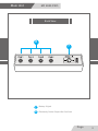
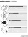
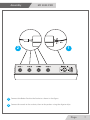
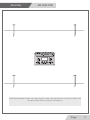
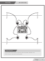
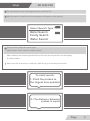
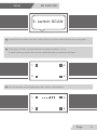
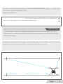
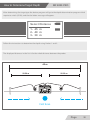
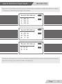
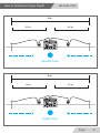
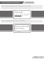
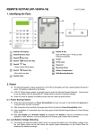
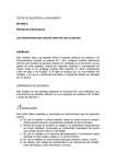
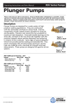
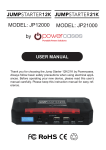
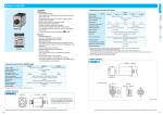
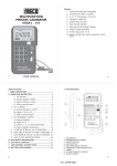
Contents User Manual Metal and Water Finder Contents Page 1 Important Notes Page 2 Overview Page 3 Main Unit Page 4 Parts Page 6 Assembly Page 7 Setup Page 10 Getting Started Page 14 How to Determine and locate Target Page 18 How to Determine Target Depth Page 20 قراءة دليل الاستخدام . جيداً قبل بدأ البحث Page 1 Important Notes User’s Manual The operating in high voltage areas would The cell phone signal interferes with the limit the results and performance device signal, so turn off the cell phone while operating Don't operate two devices with same Don't store in high temperature or high method of search at the same place humidity Disconnect the batteries before long The operator Must remove any metals time storage that might affect the search operation. eg:Rings,wrist watch, belt.... Any attempt to tamper wıth the device or unapproved maintenance would void the For best power endurance and reliability, use warranty. high quality batteries. The user must practice before starting the detection operations and discoveries. Store in Cool and dry place 15-40 C 5%-75% humidity Read & Understand The User's manual before using this device Page 2 Overview MF 8000 PRO (MF 8000 PRO) is a professional detection device. It works with geophysical application technology to measure the soil electronic resistance levels to determine the target location such as burials, gold, cavity, treasures to extended depths. (MF 8000 PRO) apply the accurate automatic measureing settings to identify the targets underground directly on the graphic screen. automatic result Each material and metal has a unique resistance value distenguish it from other materials and metals. then underground materials interact with the soil forming a electrical field (or electriacal resistance), each metal has its own resistance different from other metals, and voids have resistance also and water as well. The device depends on precise geophysical identification for electrical resistance levels to detect and locate the targets underground. the device has a four power outputs. The probes planted in the soil connected to the outputs to distribute the waves through the ground. after powering the device, the automatic measuring process will start between the power poles to locate materials and metals in the search area. After great experiments we've reached to the concept of controlling the wave length and width besides the transmitted frequencies from the device to the ground , Therefore the user could select the specified search distance and depth easily and precisely up to 90 %. This technology works for the first time now with MWF Products . Search Operation: Search System: Search for Gold, Metals , Treasures, Water and Voids. Automatic measurement for soil electrical resistance levels, to identify the metal and other targets resistance. Operating Processor: Microcontroller Processing Type: Measure and analyse the electrical resistance level and the pole pool (IP) AutoScan. Search Depth Program: Search Area Program: 70m , Depth is determined automatically 1250 m2 Page 3 Main Unit MF 8000 PRO Front View 6 1 5 4 3 2 1 Power Switch (ON/OFF) 4 Navigation and Selection Button (Move) 2 Escape and Restart Button (Esc) 5 Start the probes scan Button (SCAN) 3 Confirm and Enter Button (Enter) 6 Display Page 4 Main Unit MF 8000 PRO Back View 8 3 7 8 7 Battery IN jack 8 Electrecity Power Output for Geo Scan Page 5 Parts MF 8000 PRO Stainless Steel Probes Stainless Steel Probes : Rigid, Rustproof, and highly conductive. Planted in the ground to connect the Device waves to the earth for the geophysical scans. Battery Pack Battery Pack: Output voltage 14.8v Li-ion, 4 cells, 2700 mA Battery Life : 9 hours endurance Cord Reels 4 Cord reels designed to facilitate the connection process during the scans. High quality wires to ensure durability and conductivity. Battery Charger INPUT : 220 v~ AC OUTPUT: 20 v -- DC Connect to the battery pack to recharge. Page 6 Assembly MF 8000 PRO 2 1 1 Connect the Batter Pack to the Socket as shown in the figure 2 Connect the cords to the sockets, then to the probes using the aligator clips Page 7 Assembly MF 8000 PRO Ditrbute the probes to the scan area squarly. make sure the distance is equal in depth and distance. Plant them as shown in the figure. Page 8 Assembly MF 8000 PRO Important Note To ensure best results make sure the area where the probe is planted is wet, otherwise pour some water onto the probe. Page 9 Setup MF 8000 PRO Turn the device on by switching the power switch to ON. After the splash screen flashes these options will appear on the display: Select Search Type Metal Search Cavity Search Water Search The user must select the search type: Metal search, Cavity Search, or Water Search. After selecting the Search type the device will show the instructions on the display As shown below. Note: once the instruction is read press (MOVE) to go to the next instruction To start search: 1- Plant the probes to the largest area possible 2- The distance between probes is equal Page 10 Setup MF 8000 PRO 3- switch SCAN Once all the instructions are read, switch SCAN to start the search between the search poles. The display will show an illustration for the probes positions 1-2-3-4. To avoid confusing results the user must plant the prbes according to the figure 1 2 3 4 The scan process will be displayed on the screen as shown below 1 2 3 4 Page 11 Setup MF 8000 PRO 1 2 3 4 1 2 3 4 1 2 3 4 1 2 3 4 1 2 3 4 Page 12 Setup MF 8000 PRO Important Note To reset the settings or to rescan press (Esc) to initiate the device and start the search over again. If there is a target in the search area the device will show the nearest probe to the target after the automatic search is finished. Page 13 Getting Started MF 8000 PRO Full Example First: Distribute the probes squarely on the search area as shown in the figure below: 15 M 15 M Page 14 Getting Started MF 8000 PRO Full Example if there is a target for example near probe 4 as shown in the figure below: Page 15 Getting Started MF 8000 PRO After the automatic search is finished as mentioned earlier two results will appear on display. The first result shows the target exsistance and postion between the probes. The sceond result shows the nearst prob to the target. 1 2 3 4 First Result Target near 1 3 2 4 Second Result The second result shows the nearest probe to the target, which in this example is probe number 4, the user must enclose target by the probes on Page 16 Getting Started MF 8000 PRO 1 2 3 4 Page 17 The shown result in the example indicates the existence of target between the probes 1-4 and 2-4, which is the bottem right corner of the search area The enclosing sterps are: First: Stopthe scan by switch (SCAN) of turn off the device Second: Draw the probes closer to the nearest probe to target Important Note: If the search area is large, it is prefered to switch off the device before moving the probes, but if the search area is not large, switch (SCAN) off then move the probes the switch it back on to avoid resetting the settings. Example: Move the probe 2 towards probes 4 and move the probe 3 towards probe 4, and make sure that the distance is equal, and move the probe 1 to the fourth vertex forming a square. Page 18 Third: rescan again using the same settings for the first scan, then switch on (SCAN) to start the scan and wait for the result Fourth: If the target enclosed successfully the next result will appear on display: Loading... Please wait Meanwhile, the device will be processing and calculating the scan date to show the result to the user about the discovered target as shown below: Target Type: Gold To show depth switch SCAN Page 19 How to Determine Target Depth MF 8000 PRO After determining the target type the device program will go to the depth determination program which require to switch (SCAN), and the the below message will appear: Select Distance 1- 45 m 2- 40 m 3- 30 m Follow the instructions to determine the depth using Probes 1 and 2. The displayed distances in the list is for the whole distance between the probes 45 m 22.50 m 22.50 m First Scan Page 20 How to Determine Target Depth MF 8000 PRO Eight scans must be done according to the list below. Reduce the distance equally from both ends (probe 1 and probe 2). Maintaining the target in the middle. Select Distance 1- 45 m 2- 40 m 3- 30 m Select Distance 4- 25 m 5- 15 m 6- 7 m Select Distance 7- 5 m 8- 3 m The figures will explain how to measure the depth gradually from the maximum distance to the minimum distance according to the data and options on the display. Page 21 How to Determine Target Depth MF 8000 PRO 45 m 22.50 m 22.50 m First Scan 40 m 20 m 20 m Second Scan Page 22 How to Determine Target Depth MF 8000 PRO 30 m 15 m 15 m Third Scan 25 m 12.5 m 12.5 m Fourth Scan Page 23 How to Determine Target Depth MF 8000 PRO 15 m 7.5 m 7.5 m Fifth Scan 7m 3.5 m 3.5 m Sixth Scan Page 24 How to Determine Target Depth MF 8000 PRO 5m 2.5 m 2.5 m Seventh Scan 3m 1.5 m 1.5 m Eighth Scan Page 25 How to Determine Target Depth MF 8000 PRO The target depth result will appear after finishing the scans as shown below: Target Depth 2 4 6 10 15 20 25 m After the target depth meesage the next message will appear: Rescan: Switch SCAN Exit: Press Esc Page 26