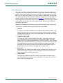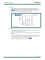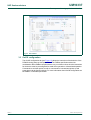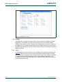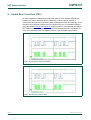
1
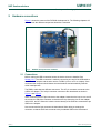
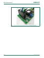
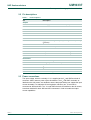
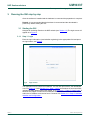
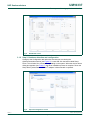
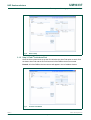
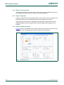
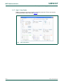
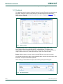
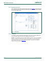
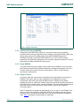
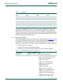
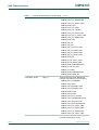
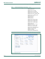
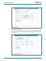
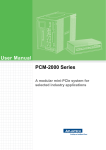
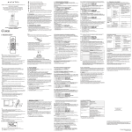
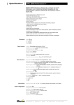
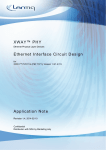
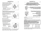
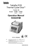
UM10337
Development kit and graphical user interface
Rev. 01 — 2 July 2009
User manual
Document information
Info
Content
Keywords
PIP8000, Graphical User Interface (GUI), User manual.
Abstract
This document gives an overview of the PIP8000 development kit setup
and graphical user interface.
UM10337
NXP Semiconductors
Development kit and graphical user interface
Revision history
Rev
Date
Description
01
20090702
First issue
Contact information
For more information, please visit: http://www.nxp.com
For sales office addresses, please send an email to: [email protected]
UM10337_1
User manual
© NXP B.V. 2009. All rights reserved.
Rev. 01 — 2 July 2009
2 of 33
UM10337
NXP Semiconductors
Development kit and graphical user interface
1. Introduction
This document describes the PIP8000 demonstration kit. Topics addressed will be the
Graphical User Interface (GUI) installation procedure, hardware connections, and how to
operate the GUI. Moreover it lists known issues and errata.
The PIP8000 web based GUI is designed for the PIP8000 and is in compliance with the
PMBus protocol specifications. The Power Management Bus (PMBus) commands that
are supported by the PIP8000 are listed in the PIP8000 data sheet. The GUI can be used
to evaluate and configure the PIP8000 for use in most given applications and to generate
output files for use in the manufacturing stage.
The demonstration kit includes the demoboard kit hardware. The main components of the
demo kit are the PIP8000, two power train PIP212s, a fan, and an I2C interface connector.
The PIP8000 GUI is available via the link on the NXP PIP8000 product website. For more
information see Section 1, Section 2 and Section 3.
Once connected to the GUI you will find the GUI has three primary sections, each
selectable using a tab control positioned horizontally in the upper left hand corner. Also
there are subsections for each section using tab controls positioned vertically in the upper
left hand corner. Section 3 describes each selection in more detail.
1.1 Demo kit contents
•
•
•
•
Demoboard, including fan
USB cable, and custom made PMBus cable
USB-to-I2C-bus adapter (interface) board
CD including: software drivers, data sheets, user manual and other relevant
information
1.2 User access request
For registration and access visit the NXP internet site (www.nxp.com). On the NXP site
you will find the design portal. In the design portal registration can be completed. Once
registered you will be linked automatically to the NXP SimPort where the registered login
name and password are needed to get access to the GUI tool.
1.3 Requirements for installation of PIP8000 PMBus controller
1.3.1 System requirements
• Windows 2000 or higher. The USB-to-I2C adapter driver is not supported in 64-bit
Vista
• Internet Explorer 6 or higher
• Default security settings (Medium in Internet Explorer 6, Medium-high for Internet
Explorer 7)
UM10337_1
User manual
© NXP B.V. 2009. All rights reserved.
Rev. 01 — 2 July 2009
3 of 33
UM10337
NXP Semiconductors
Development kit and graphical user interface
1.3.2 Software Installation
1. Install the USB-to-I2C adapter from disk.
2. Administrators rights are required to be able install the ActiveX control component
PMBusCtrl.ocx.
When installing of the PMBusCtrl.ocx file a pop-up will appear. Click: Install ActiveX
Control.
The installation progress of ActiveX control is given on the IE status bar If, instead of
the login screen, a box with a red cross appears one of the following problems may be
occurring:
– ActiveX is not enabled: change the browser security settings.
– ActiveX controls are not supported: Install Microsoft Internet Explorer 6 or higher to
view the site.
– A pop-up blocker is switched on. Please switch off this pop-up blocker.
– You do not have the correct user rights: Please contact the system administrator.
– The internet security policy blocks ActiveX controls: Please contact the system
administrator.
3. From the Configuration page in the GUI install the device drivers. Administration rights
are required for installing the device drivers.
1.3.3 Hardware installation
1. After installing the software drivers and GUI, select "Manual" on the top right of the
screen to get a user manual and detailed connection information.
2. Connect USB-to-I2C adapter to the PC.
3. Connect the PIP8000 demoboard I2C connector to the USB-to-I2C adapter.
4. Connect 12 V power to the PIP8000 demoboard.
5. The software can be loaded without the hardware, but with limited functionality.
UM10337_1
User manual
© NXP B.V. 2009. All rights reserved.
Rev. 01 — 2 July 2009
4 of 33
UM10337
NXP Semiconductors
Development kit and graphical user interface
2. Hardware connections
Figure 1 shows the content of the PIP8000 development kit. The following chapters will
describe how the different components should be connected.
Fig 1.
PIP8000 development kit: Hardware
2.1 Connections
Before making the USB connection ensure the device drives are installed. See
Section 1.3.2. The USB connection is made by connecting one end of the USB cable to
the USB-to-I2C adapter and the other end to a USB 2.0 port on a PC or a laptop. Once
connected the computer should detect the new hardware and automatically start the
driver install process.
The PMBus cable has two different connectors. The 2x7 pin connector connects to the
USB-to-I2C adapter. The 2x6 pin connector connects to the demoboard as shown in
Figure 1 and Figure 2.
When connecting the 2x7 pin connector to the adapter, locate the wire loop on one end of
the connector. Attach the connector so that the wire loop shorts the pins on the adapter
called VCC, and VP. When this is done note the identity of the GND wire connected to pin
GND on the adapter.
Now connect the 2x6 pin connector the demoboard. When doing so arrange the
connector so that the GND wire connects to the pin labeled GND on the demoboard.
UM10337_1
User manual
© NXP B.V. 2009. All rights reserved.
Rev. 01 — 2 July 2009
5 of 33
UM10337
NXP Semiconductors
Development kit and graphical user interface
Fig 2.
2x7 pin connector and connection overview on the PIP8000 demoboard
UM10337_1
User manual
© NXP B.V. 2009. All rights reserved.
Rev. 01 — 2 July 2009
6 of 33
UM10337
NXP Semiconductors
Development kit and graphical user interface
2.2 Pin descriptions
Table 1.
Pin descriptions
Pin
Description
Adapter
VCC
3.3 V supply dedicated for the I2C bus pull-up resistors
SSN
Not used
MISO
Not used
MOSI
Not used
GND
Not used
SCLK
Not used
3.3V
Not used
VP
Apply the I2C voltage to this pin by shorting it to VCC. (Done by
connector)
SCL
I2C clock
GND
Ground or reference point
SDA
I2C data
IN
This pin is used to detect the PMBus Alert# signal
OUT
This pin is used to drive the PMBus Control signal
5V
Not used
Demoboard
CTRL
PMBus control signal
RST
Pulling this pin low momentarily will reset the PIP8000, not wired.
GND
Ground
SDA
I2C data
SCL
I2C clock
ALRT
PMBus Alert# signal
2.3 Power connections
The input voltage, which is nominally 12 V, is supplied to the Vin and GND terminals of
connector J650 in order to power up the demoboard. The Vin and GND terminals, as
labelled on the silk screen, are doubled to ensure that input cabling can support the input
current demands. For evaluation of load regulation, efficiency etc., a load can be
connected to J652 and J653. The Vout and GND terminals, as labelled on the silk screen,
have been doubled for both J652 and J653 connectors in order to handle the output
current capabilities.
UM10337_1
User manual
© NXP B.V. 2009. All rights reserved.
Rev. 01 — 2 July 2009
7 of 33
UM10337
NXP Semiconductors
Development kit and graphical user interface
3. Running the GUI step by step
Once the software is installed and the hardware is connected the preparation is complete.
Remark: It is recommended that the hardware is connected and the demoboard is
powered up before starting the GUI.
3.1 Starting the GUI
Navigate to the design Portal on the NXP website (see Section 1.2) The login screen will
appear as in Figure 3.
3.1.1 Step 1: Login
Enter the login information (received after registering) in the appropriate field and press
the login button, see Figure 3.
Fig 3.
Login screen
The application will be loaded and initialized. The GUI will open with the GUI dashboard
view, see Figure 4. If after Section 3.1.1 “Step 1: Login” the hardware is found and fields
indicate PIP8000 defaults have been loaded, go to Section 3.1.7 “Step 7: Clear Faults”. If
this does not happen it means that no hardware was detected because the USB drivers
and/or the I2C address could not be found. Continue with Section 3.1.2 “Step 2: Hardware
detection and configuration”.
UM10337_1
User manual
© NXP B.V. 2009. All rights reserved.
Rev. 01 — 2 July 2009
8 of 33
UM10337
NXP Semiconductors
Development kit and graphical user interface
Fig 4.
Dashboard screen
3.1.2 Step 2: Hardware detection and configuration
Change to the Configuration tab and make sure that you are viewing the
Options/Connection section (see Figure 5). Locate and click the button called Setup
Driver. This will take 10 to 30 seconds depending on the system. When the device drivers
dialog box appears (see Figure 6), the driver installation process is complete. Rerun the
Setup Driver process when USB-to-I2C adapter is disconnected or replaced.
Fig 5.
Options/Configuration screen
UM10337_1
User manual
© NXP B.V. 2009. All rights reserved.
Rev. 01 — 2 July 2009
9 of 33
UM10337
NXP Semiconductors
Development kit and graphical user interface
Fig 6.
Driver setup
3.1.3 Step 3: Find I2C with Auto Find
Once the drivers have been set up the GUI will allow the Auto Find option to work. Click
the button Auto Find and the GUI will locate all of the PMBus devices connected.
Remark: All of the PMBus devices connect will appear in the I2C address list box.
Fig 7.
I2C Auto Find button
UM10337_1
User manual
© NXP B.V. 2009. All rights reserved.
Rev. 01 — 2 July 2009
10 of 33
UM10337
NXP Semiconductors
Development kit and graphical user interface
3.1.4 Step 4: Connection test
Pressing the test button checks the system. This test will ping the PIP8000 and respond
with a dialog box informing you of a successful or unsuccessful test.
3.1.5 Step 5: Target test
Press the reset button to load the default settings. This will send a reset command to the
PIP8000 and then the PIP embedded software version appears on the screen.
At this point the GUI should have uploaded the coefficient and default values from the
PIP8000 NVRAM. Clicking the status button reads the PMBus status registers in the
PIP8000.
3.1.6 Step 6: Dashboard screen
Figure 8 shows the Dashboard screen. After the target I2C has correctly been found and
the target is reset, the dashboard will show the status of the demoboard.
Fig 8.
Dashboard screen
UM10337_1
User manual
© NXP B.V. 2009. All rights reserved.
Rev. 01 — 2 July 2009
11 of 33
UM10337
NXP Semiconductors
Development kit and graphical user interface
3.1.7 Step 7: Clear Faults
PMBus commands can now be issued to control the power train. Errors can reset by
pressing the button Clear Faults (see Figure 9).
Fig 9.
Clear Faults button
UM10337_1
User manual
© NXP B.V. 2009. All rights reserved.
Rev. 01 — 2 July 2009
12 of 33
UM10337
NXP Semiconductors
Development kit and graphical user interface
3.2 Dashboard
The dashboard has four sections: Voltage, Current, Fans, and Thermals. In these sections
the output voltage, the various limits, and set up the fault responses as specified by
PMBus are controlled. This example describes the output voltage (see Figure 10). The
other sections are similar.
Fig 10. Output voltage
The output voltage scale will always start from 0 and stop at VOUT_MAX. The
VOUT_MAX control is found on the ON/OFF Configuration tab. The range is not
representative of the demoboard output range. The desired output value may be set by
using the slider control or by manually entering a value in the numeric control.
Remark: When using the numeric control, use the TAB key to enter the new value.
Use the warn and fault limits to set up the operating range. Use the OV fault and UV fault
buttons to set up the desired fault responses.
When setting up a desired fault response, the following dialog box will appear.
Fig 11. Vout fault response
UM10337_1
User manual
© NXP B.V. 2009. All rights reserved.
Rev. 01 — 2 July 2009
13 of 33
UM10337
NXP Semiconductors
Development kit and graphical user interface
3.2.1 Responses
The results of the Retry Settings and the Delay Time settings can have a different result
depending on the type of response that suits the requirements. Experiment with these
settings using the demoboard to get a feel for how they work. When working with output
faults, you will notice the PIP8000 will need to re-enable the output to test the fault when
retry settings are used. It does not need to enable the output to retry the other faults. For
example, assume an input voltage fault (based on Figure 12). The response is to shut
down the regulator and then continuously check every two seconds to see if the input fault
is gone (Retry Continuously). If the input voltage falls back into range the PIP8000 will
re-enable the power train.
Remark: The PIP8000 will not enable the output while it checks the input voltage status.
There are four selectable response types as specified by the PMBus.
• Continue:
If Continue is selected the PIP8000 will not respond to the given fault. However, the
appropriate status bits will be set in the status register. When this option is selected
the Retry Settings and Delay Time Units will be disabled. This selection could also be
seen as an ignore setting.
• Continue for delay time:
This option will allow the fault condition to continue for a specified amount of time.
This is usedwhen the system may be able to tolerate a fault condition for a short
amount of time. It may be more beneficial for the rest of the system to give this fault a
chance to fix itself before responding to it. Ultimately if the fault does not correct itself
the PIP8000 will shut down the power train by disabling the analog Pulse Width
Modulation (PWM) controller and remain in this state until the PIP8000 receives a
Clear Faults or a reset command. This option will also allow a retry.
• Shut-down:
With this option the PIP8000 will disable the analog PWM controller as fast as it can
when a fault condition is reached. The retry settings in this case will use the delay
time to set the off-period before a retry event.
• Disable output:
This option will disable the output of an analog controller after the specified delay
time. The PIP8000 will not attempt a retry and remain in this state until it receives a
Clear Faults or a reset command.
UM10337_1
User manual
© NXP B.V. 2009. All rights reserved.
Rev. 01 — 2 July 2009
14 of 33
UM10337
NXP Semiconductors
Development kit and graphical user interface
3.2.2 Graphs
On the dashboard you will see three graphs (bottom of screen), one for voltage (see
Figure 12), one for current, and one for temperature. The Y-axis for all graphs is
auto-ranging and no control is given for this. The X-axis will also auto range. However, by
using the right mouse button a history length option will appear.
Fig 12. Voltage graph
3.2.3 Fan
The fan controls allows switching-on or switching-off of up to two fans, as well as read
their speeds (Rotations Per Minute (RPM)).
Remark: The PIP8000 is designed to switch the fans on or off. It cannot PWM control the
fan speed.
The Fan Config button allows the user to enable or disable the control of each fan and
select the fans pulses per rotation. The data sheet about the fans should provide the
information for its particular pulses per rotation. See Figure 13.
Remark: The demoboardis designed to support 12 V fans only.
UM10337_1
User manual
© NXP B.V. 2009. All rights reserved.
Rev. 01 — 2 July 2009
15 of 33
UM10337
NXP Semiconductors
Development kit and graphical user interface
Fig 13. Fan control
3.3 On/Off configuration
The On/Off configuration tab (see Figure 14) allows the instruction of the behavior of the
PIP8000 during power-up and power-down. The PMBus specification takes into
consideration that a PMBus compliant device may run without a host, thus the instructions
for the device must be preconfigured for stand alone operation or host assisted operation.
Commands to set either option as well as commands for host-assisted power-up and
power-down can be found in this tab. For more information about On/Off configuration see
the PMBus or PIP8000 specification.
UM10337_1
User manual
© NXP B.V. 2009. All rights reserved.
Rev. 01 — 2 July 2009
16 of 33
UM10337
NXP Semiconductors
Development kit and graphical user interface
Fig 14. Configuration screen
3.4 Design
The design tab is focused on creating custom macros based on the PMBus commands
supported by the PIP8000. Use these functions to build a list of commands that the
PIP8000 should send or receive. If multiple units (demoboards) are present in parallel on
the PMBus line, the unit which should respond to the PMBus command can be selected
by addressing that particular unit with its slave address and then transmitting the specific
PMBus command.
3.4.1 Script
On the left hand side of the screen you see a category list of supported commands (see
Figure 15). Next to the list there are macro function buttons that allow adding, deleting,
and arranging the commands as well as load and save scripts. When building a script the
I2C address column and the parameters column may be editable depending on the
command. Once the user has generated a list of commands, they will need to select the
run tab to execute the script.
UM10337_1
User manual
© NXP B.V. 2009. All rights reserved.
Rev. 01 — 2 July 2009
17 of 33
UM10337
NXP Semiconductors
Development kit and graphical user interface
Fig 15. Script screen
Selecting different commands and using the Add button a complete sequence of
commands can be generated to form a script. See Figure 16. When units are in parallel
the commands will be specific for the selected I2C address. Pauses can be added
between each added command. The generated scripts can be saved to either a local disk
or the web. From these locations they can be reloaded.
Fig 16. Building scripts
UM10337_1
User manual
© NXP B.V. 2009. All rights reserved.
Rev. 01 — 2 July 2009
18 of 33
UM10337
NXP Semiconductors
Development kit and graphical user interface
Example of building a script:
1. Setting Operation and On/Off Configuration commands defined to specific user.
2. Add Pause.
3. Set Vout to 3.5 V.
4. Store to NVRAM.
3.4.2 Run a script
Figure 17 shows the upper left hand corner of the Run section. The monitoring buttons are
de-highlighted at present. These will be discussed in Section 3.4.3. In the Design box
there are four control buttons: Play All, Step, Pause, and Stop. Use these buttons to
control how the macro will be executed. The area located just above these controls will
display the script process. The Log tab will display every command sent with a status of
the command in case history checking is desired. The Values tab will display the values
returned from the PIP8000. If a command is sent that does not have a returned value,
such as the simple script shown in Figure 17, then no value will be displayed on the Value
tab. However, the log tab will still show that the command was sent.
Fig 17. Run screen
3.4.3 Monitoring
The Monitoring function will run a preconfigured macro that allows the user to take a
closer look at voltages, currents, and temperature values. Once the monitoring has
started, additional tabs will be added to the current Values and Log tabs along the top of
the screen. While monitoring is running custom macros can still be executed.
UM10337_1
User manual
© NXP B.V. 2009. All rights reserved.
Rev. 01 — 2 July 2009
19 of 33
UM10337
NXP Semiconductors
Development kit and graphical user interface
Fig 18. Graph monitor options
Fig 19. Graph color settings
Example:
1. Step 1: Select preferred signals on a specific graph (e.g. VIN, IIN, Vout and
Temperature).
2. Step 2: Close.
3. Step 3: Press PLAY button in the Monitoring section
UM10337_1
User manual
© NXP B.V. 2009. All rights reserved.
Rev. 01 — 2 July 2009
20 of 33
UM10337
NXP Semiconductors
Development kit and graphical user interface
Fig 20. Graph screen
3.5 Configuration
The Configuration tab contains tools for setting up the GUI. The screen visited as part of
the initial set-up. See Section 3.3. This is necessary the first time the GUI is run. If any
modifications are made to the demoboard or additional boards are connected to the
SMBus the user will need to return to this screen and reconfigure the GUI accordingly.
UM10337_1
User manual
© NXP B.V. 2009. All rights reserved.
Rev. 01 — 2 July 2009
21 of 33
UM10337
NXP Semiconductors
Development kit and graphical user interface
3.5.1 Options/Connections
The Configuration tab contains tools for setting up the GUI (Figure 21). Here the user will
set up one or more device I2C addresses and/or test communications, reset the PIP8000,
and check the PMBus status.
Fig 21. GUI settings
3.5.2 Coefficient
The PIP8000 sends a hexadecimal representation of any value to the host. Before the
host can properly decode the value, the coefficients must be correct.
Remark: The PIP8000 demo has stored the coefficient. However, if any of the hardware
scaling is modified, the coefficients will need to be modified. For more information on
coefficients and data types, see the PMBus specification. For the process details of
setting coefficients please see Section 3.6.
UM10337_1
User manual
© NXP B.V. 2009. All rights reserved.
Rev. 01 — 2 July 2009
22 of 33
UM10337
NXP Semiconductors
Development kit and graphical user interface
Fig 22. Change coefficients
3.5.3 Storing and restoring NVRAM
During start-up the RESTORE_USER_ALL command is called to store all USER
parameters to the running configuration. When settings are changed STORE_USER_ALL
can be used to store the changed settings to the USER NVRAM storage area.
RESTORE_DEFAULT_ALL and STORE_DEFAULT_ALL can be used to change
parameters in the DEFAULT storage area. The running configuration needs to be used to
swap between USER and DEFAULT storage area.
3.5.4 Dump NVRAM
This option allows saving the volatile memory space of the PIP8000 to a text document.
After clicking the button Dump NVRAM a dialog box will appear prompting the user for a
file name. Select the location of choice and give the file a name. The GUI will then
generate the text document.
3.5.5 Dump to device
This option allows the user to store a configuration file to the volatile memory space of
PIP8000. This can be useful for initial configuration if a PIP8000 has not been
programmed. After clicking the button NVRAM to Device a dialog box will appear
prompting the user for a file name. Select the file of choice and the GUI will use that file to
write parameters to volatile memory space of PIP8000. The buttons Store Default All and
Store User All can be used to store the volatile memory space of the PIP8000 to
non-volatile space.
Eight I2C addresses are possible by pinstrapping pins 9, 10 and 11 of the PIP8000. This
can be done by either shorting or leaving the AD0, AD1 and AD2 connections open at
connector J501. For example, when AD0, AD1, and AD2 are shorted the IC address is
0x26. Table 2 indicates the eight possible I2C addresses.
UM10337_1
User manual
© NXP B.V. 2009. All rights reserved.
Rev. 01 — 2 July 2009
23 of 33
UM10337
NXP Semiconductors
Development kit and graphical user interface
Table 2.
I2C addresses
AD0
AD1
AD2
I2C address
Open
Open
Open
0x34
Open
Open
Short
0x2C
Open
Short
Open
0x30
Open
Short
Short
0x28
Short
Open
Open
0x32
Short
Open
Short
0x2A
Short
Short
Open
0x2E
Short
Short
Short
0x26
In addition if an invalid I2C address is detected during power-up of the PIP8000, bit[7] of
the CONFIG_COMMAND will be set. The result is that the PIP8000 will not start as a
PMBus device. It will start the I2C interface to enable manipulation of the volatile and
non-volatile memory space. After clearing bit[7] of the CONFIG_COMMAND the PMBus
operation will start Power-up/power-down and warning and fault handling. This is done to
prevent starting with incorrect coefficients.
3.5.6 Mode configuration
The PIP8000 supports Linear mode and Direct mode data formats (see Figure 23). These
modes can be switched real time. However, they are typically selected at the beginning of
the application and stored in NVRAM. The table below shows which commands are
affected by mode settings. From the table it can be noted that three modes are supported:
• All data formats in direct mode
• All data in linear mode not using VOUT_MODE
• All data in linear mode using VOUT_MODE for the VOUT related commands
Table 3.
Commands affected by the mode setting
VOUT_MODE
CONFIG_COMMAND
Mode
Don’t care
Bit[1] = 0
Direct mode for all commands
bits[7...5] NOT 000
Bit[1] = 1
Linear mode NOT using VOUT_MODE 5bit
mantissa. Commands in Linear mode are:
PMBUS_VOUT_COMMAND
PMBUS_VOUT_MAX
PMBUS_VOUT_MARGIN_HIGH
PMBUS_VOUT_MARGIN_LOW
PMBUS_READ_VOUT
PMBUS_VOUT_TRIM
PMBUS_VOUT_CAL_OFFSET
PMBUS_VOUT_TRANSITION_RATE
PMBUS_VOUT_SCALE_LOOP
PMBUS_VOUT_SCALE_MONITOR
PMBUS_VOUT_OV_FAULT_LIMIT
PMBUS_VOUT_OV_WARN_LIMIT
UM10337_1
User manual
© NXP B.V. 2009. All rights reserved.
Rev. 01 — 2 July 2009
24 of 33
UM10337
NXP Semiconductors
Development kit and graphical user interface
Table 3.
Commands affected by the mode setting …continued
VOUT_MODE
CONFIG_COMMAND
Mode
PMBUS_VOUT_UV_WARN_LIMIT
PMBUS_VOUT_UV_FAULT_LIMIT
PMBUS_READ_IOUT
PMBUS_IOUT_CAL_GAIN
PMBUS_IOUT_CAL_OFFSET
PMBUS_IOUT_OC_FAULT_LIMIT
PMBUS_IOUT_OC_LV_FAULT_LIMIT
PMBUS_IOUT_OC_WARN_LIMIT
PMBUS_READ_VIN
PMBUS_VIN_ON
PMBUS_VIN_OFF
PMBUS_VIN_OV_FAULT_LIMIT
PMBUS_VIN_OV_WARN_LIMIT
PMBUS_VIN_UV_WARN_LIMIT
PMBUS_VIN_UV_FAULT_LIMIT
PMBUS_READ_IIN
PMBUS_IIN_OC_FAULT_LIMIT
PMBUS_IIN_OC_WARN_LIMIT
PMBUS_READ_TEMPERATURE_1
PMBUS_OT_FAULT_LIMIT
PMBUS_OT_WARN_
PMBUS_READ_TEMPERATURE_
PMBUS_READ_USER_AD
Linear bits[7..5] 000
Bit[1] = 1
Linear mode using VOUT_MODE 5 bit
mantissa. Commands in Linear mode for:
PMBUS_VOUT_COMMAND
PMBUS_VOUT_MAX
PMBUS_VOUT_MARGIN_HIGH
PMBUS_VOUT_MARGIN_LOW
PMBUS_READ_VOUT
PMBUS_VOUT_TRIM
PMBUS_VOUT_CAL_OFFSET
PMBUS_VOUT_TRANSITION_RATE
PMBUS_VOUT_SCALE_LOOP
PMBUS_VOUT_SCALE_MONITOR
PMBUS_VOUT_OV_FAULT_LIMIT
PMBUS_VOUT_OV_WARN_LIMIT
PMBUS_VOUT_UV_WARN_LIMIT
PMBUS_VOUT_UV_FAULT_LIMIT
Línear mode NOT using VOUT_MODE 5 bit
mantissa (normal linear_mode)
UM10337_1
User manual
© NXP B.V. 2009. All rights reserved.
Rev. 01 — 2 July 2009
25 of 33
UM10337
NXP Semiconductors
Development kit and graphical user interface
Table 3.
Commands affected by the mode setting …continued
VOUT_MODE
CONFIG_COMMAND
Mode
PMBUS_READ_IOUT
PMBUS_IOUT_CAL_GAIN
PMBUS_IOUT_CAL_OFFSET
PMBUS_IOUT_OC_FAULT_LIMIT
PMBUS_IOUT_OC_LV_FAULT_LIMIT
PMBUS_IOUT_OC_WARN_LIMIT
PMBUS_READ_VIN
PMBUS_VIN_ON
PMBUS_VIN_OFF
PMBUS_VIN_OV_FAULT_LIMIT
PMBUS_VIN_OV_WARN_LIMIT
PMBUS_VIN_UV_WARN_LIMIT
PMBUS_VIN_UV_FAULT_LIMIT
PMBUS_READ_IIN
PMBUS_IIN_OC_FAULT_LIMIT
PMBUS_IIN_OC_WARN_LIMIT
PMBUS_READ_TEMPERATURE_1
PMBUS_OT_FAULT_LIMIT
PMBUS_OT_WARN_
PMBUS_READ_TEMPERATURE_
PMBUS_READ_USER_AD
Fig 23. Direct/Linear mode
UM10337_1
User manual
© NXP B.V. 2009. All rights reserved.
Rev. 01 — 2 July 2009
26 of 33
UM10337
NXP Semiconductors
Development kit and graphical user interface
Fig 24. Mode set
3.6 Calibrating coefficients
This section describes calibrating the Vout command. Using the Coefficients tab will make
this process easier. Two measurement points will be needed to find the slope of each
measurement.
Fig 25. Calibrating coefficients
UM10337_1
User manual
© NXP B.V. 2009. All rights reserved.
Rev. 01 — 2 July 2009
27 of 33
UM10337
NXP Semiconductors
Development kit and graphical user interface
•
•
•
•
•
Power supply
Load
Voltage meter
Current meter
Temperature probe
3.6.1 Calibrating the Vout command
To calibrate the Vout command, only a voltmeter will be necessary.
1. Step 1: From the Dashboard/Main tab set the OV and UV fault and warning outside of
the calibration rang. i.e. Set UV fault and warn to 0 V and OV fault and warn to 10 V.
This will give a wide working range without causing the PIP8000 to respond to voltage
fault limits.
2. Step 2: The demoboard can maintain stability down to ~500 mV, so somewhere
between 1 V and 500 mV will be good enough for the first data point. Using the
Adjust Voltage slider on the main page; set Vout between 0.5 V and 1 Volt. The best
way to do this is to type “.500” or “1.0” into the Adjust Vout digital control.
Remark: When calibrating VOUT_COMMAND ignore the measured voltage for now.
3. Step 3: Return to the Coefficients tab: Make sure VOUT_COMMAND is selected for
Coefficient Calculation. Using a voltmeter, measure the voltage at TP650 and enter
that value into the Measured Low Value digital control. Click the Read button next to
the Low Value from Device digital indicator.
4. Step 4: Now we need to select a high value for VOUT_COMMAND using the Adjust
Voltage slider on the main page; set Vout between 4 V and 5 V. The best way to do this
is to type “.4.5” into the Adjust Vout digital control.
Remark: When calibrating VOUT_COMMAND ignore the measured voltage for now.
5. Step 5: Return to the Coefficients tab: Make sure VOUT_COMMAND is selected for
Coefficient Calculation. Using a voltmeter, measure the voltage at TP650 and enter
that value into the Measured High Value digital control. Click the Read button next to
the High Value from Device digital indicator.
6. Step 6: Now that the two data points have been found, the GUI can calculate the
Y = mx + b values otherwise known as the coefficients. Click the Calculate button,
and the GUI will display its calculation in the Scale, Offset, and Exponent indicators.
When this is done click the Apply button to assign the new coefficients to the
VOUT_COMMAND coefficients register. The new values will be temporally stored
until the next power cycle command or rest command. To save these values
permanently, click the Store User All button and the values will be stored into the
non-volatile memory of the PIP8000.
For the remaining values use the lab equipment to vary input voltages, input current,
output current.
Remark: When calibrating temperatures allow the board to thermally settle before taking
measurements. This could take up to 30 or 40 minutes. Do not make any external
adjustments beyond the ability of the demoboard. Keep in mind that the Vreg industry has
the habit of rating VRMs/VRDs as maximum current.
UM10337_1
User manual
© NXP B.V. 2009. All rights reserved.
Rev. 01 — 2 July 2009
28 of 33
UM10337
NXP Semiconductors
Development kit and graphical user interface
The PIP212 is rated for 35 A with airflow, for an output voltage of 0.8 V up to 3.5 V.
Attempting to load the demoboard at 40 A per phase, an output voltage of 5 V will cause
damage.
Below are some calibration suggestions that do not damage the demoboard:
•
•
•
•
•
•
•
For calibration of Vout and Vin, be aware that no output load is connected
For calibration of the currents and temperature an output load is necessary
Avoid output loading greater than 120 W per phase
Set Vout to 1.1 V to 1.5 V
For Vin calibration 9 V low, 14 V high
For Iout Calibration 10 A low, 50 A high
Use the Iout low and high for input current measurements and thermals
UM10337_1
User manual
© NXP B.V. 2009. All rights reserved.
Rev. 01 — 2 July 2009
29 of 33
UM10337
NXP Semiconductors
Development kit and graphical user interface
4. Packet Error Correction (PEC)
On the Configuration, Options/Connections tab, there will be a checkbox labeled Use
Packet Error Check. Check this box to enable PEC. This box can be checked or
unchecked at any time during operation and the PIP8000 will respond accordingly. There
will not be any noticeable change in the GUI whether PEC is or is not enabled. Without
going into details Figure 26 and Figure 27 show the read Vout command with and without
PEC enabled. Notice the extra packet during the transaction when PEC is enabled. For
more information about PEC and PMBus Protocols. See the PMBus Specification.
Fig 26. I2C waveforms with PEC enabled
Fig 27. I2C waveforms without PEC
UM10337_1
User manual
© NXP B.V. 2009. All rights reserved.
Rev. 01 — 2 July 2009
30 of 33
UM10337
NXP Semiconductors
Development kit and graphical user interface
5. Errata
• Fan 2 counter is not working.
• USB-to-I2C dongle used is not supported under vista 64 bit. It is supported in Vista
32 bit.
UM10337_1
User manual
© NXP B.V. 2009. All rights reserved.
Rev. 01 — 2 July 2009
31 of 33
UM10337
NXP Semiconductors
Development kit and graphical user interface
6. Legal information
6.1
Definitions
Draft — The document is a draft version only. The content is still under
internal review and subject to formal approval, which may result in
modifications or additions. NXP Semiconductors does not give any
representations or warranties as to the accuracy or completeness of
information included herein and shall have no liability for the consequences of
use of such information.
6.2
Suitability for use — NXP Semiconductors products are not designed,
authorized or warranted to be suitable for use in medical, military, aircraft,
space or life support equipment, nor in applications where failure or
malfunction of a NXP Semiconductors product can reasonably be expected to
result in personal injury, death or severe property or environmental damage.
NXP Semiconductors accepts no liability for inclusion and/or use of NXP
Semiconductors products in such equipment or applications and therefore
such inclusion and/or use is at the customer’s own risk.
Applications — Applications that are described herein for any of these
products are for illustrative purposes only. NXP Semiconductors makes no
representation or warranty that such applications will be suitable for the
specified use without further testing or modification.
Disclaimers
General — Information in this document is believed to be accurate and
reliable. However, NXP Semiconductors does not give any representations or
warranties, expressed or implied, as to the accuracy or completeness of such
information and shall have no liability for the consequences of use of such
information.
Right to make changes — NXP Semiconductors reserves the right to make
changes to information published in this document, including without
limitation specifications and product descriptions, at any time and without
notice. This document supersedes and replaces all information supplied prior
to the publication hereof.
Export control — This document as well as the item(s) described herein
may be subject to export control regulations. Export might require a prior
authorization from national authorities.
6.3
Notice: All referenced brands, product names, service names and trademarks
are the property of their respective owners.
I2C-bus — logo is a trademark of NXP B.V.
UM10337_1
User manual
Trademarks
© NXP B.V. 2009. All rights reserved.
Rev. 01 — 2 July 2009
32 of 33
UM10337
NXP Semiconductors
Development kit and graphical user interface
7. Contents
1
1.1
1.2
1.3
1.3.1
1.3.2
1.3.3
2
2.1
2.2
2.3
3
3.1
3.1.1
3.1.2
3.1.3
3.1.4
3.1.5
3.1.6
3.1.7
3.2
3.2.1
3.2.2
3.2.3
3.3
3.4
3.4.1
3.4.2
3.4.3
3.5
3.5.1
3.5.2
3.5.3
3.5.4
3.5.5
3.5.6
3.6
3.6.1
4
5
6
6.1
6.2
6.3
7
Introduction . . . . . . . . . . . . . . . . . . . . . . . . . . . . 3
Demo kit contents . . . . . . . . . . . . . . . . . . . . . . . 3
User access request . . . . . . . . . . . . . . . . . . . . . 3
Requirements for installation of
PIP8000 PMBus controller . . . . . . . . . . . . . . . . 3
System requirements . . . . . . . . . . . . . . . . . . . . 3
Software Installation . . . . . . . . . . . . . . . . . . . . . 4
Hardware installation . . . . . . . . . . . . . . . . . . . . 4
Hardware connections . . . . . . . . . . . . . . . . . . . 5
Connections . . . . . . . . . . . . . . . . . . . . . . . . . . . 5
Pin descriptions . . . . . . . . . . . . . . . . . . . . . . . . 7
Power connections . . . . . . . . . . . . . . . . . . . . . . 7
Running the GUI step by step. . . . . . . . . . . . . . 8
Starting the GUI . . . . . . . . . . . . . . . . . . . . . . . . 8
Step 1: Login. . . . . . . . . . . . . . . . . . . . . . . . . . . 8
Step 2: Hardware detection and configuration . 9
Step 3: Find I2C with Auto Find. . . . . . . . . . . . 10
Step 4: Connection test . . . . . . . . . . . . . . . . . 11
Step 5: Target test. . . . . . . . . . . . . . . . . . . . . . 11
Step 6: Dashboard screen . . . . . . . . . . . . . . . 11
Step 7: Clear Faults . . . . . . . . . . . . . . . . . . . . 12
Dashboard . . . . . . . . . . . . . . . . . . . . . . . . . . . 13
Responses . . . . . . . . . . . . . . . . . . . . . . . . . . . 14
Graphs . . . . . . . . . . . . . . . . . . . . . . . . . . . . . . 15
Fan . . . . . . . . . . . . . . . . . . . . . . . . . . . . . . . . . 15
On/Off configuration . . . . . . . . . . . . . . . . . . . . 16
Design . . . . . . . . . . . . . . . . . . . . . . . . . . . . . . 17
Script . . . . . . . . . . . . . . . . . . . . . . . . . . . . . . . 17
Run a script . . . . . . . . . . . . . . . . . . . . . . . . . . 19
Monitoring . . . . . . . . . . . . . . . . . . . . . . . . . . . . 19
Configuration . . . . . . . . . . . . . . . . . . . . . . . . . 21
Options/Connections . . . . . . . . . . . . . . . . . . . 22
Coefficient. . . . . . . . . . . . . . . . . . . . . . . . . . . . 22
Storing and restoring NVRAM . . . . . . . . . . . . 23
Dump NVRAM . . . . . . . . . . . . . . . . . . . . . . . . 23
Dump to device. . . . . . . . . . . . . . . . . . . . . . . . 23
Mode configuration . . . . . . . . . . . . . . . . . . . . . 24
Calibrating coefficients . . . . . . . . . . . . . . . . . . 27
Calibrating the Vout command. . . . . . . . . . . . . 28
Packet Error Correction (PEC) . . . . . . . . . . . . 30
Errata. . . . . . . . . . . . . . . . . . . . . . . . . . . . . . . . . 31
Legal information. . . . . . . . . . . . . . . . . . . . . . . 32
Definitions . . . . . . . . . . . . . . . . . . . . . . . . . . . . 32
Disclaimers . . . . . . . . . . . . . . . . . . . . . . . . . . . 32
Trademarks. . . . . . . . . . . . . . . . . . . . . . . . . . . 32
Contents . . . . . . . . . . . . . . . . . . . . . . . . . . . . . . 33
Please be aware that important notices concerning this document and the product(s)
described herein, have been included in section ‘Legal information’.
© NXP B.V. 2009.
All rights reserved.
For more information, please visit: http://www.nxp.com
For sales office addresses, please send an email to: [email protected]
Date of release: 2 July 2009
Document identifier: UM10337_1