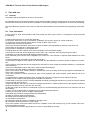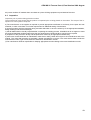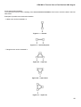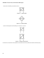
1
CEN WS 25 Trusses Part A, Final Version 2008 August
CEN WS 25 N 0136
CEN WS 25
Lifting and Load-bearing Equipment
for Stages and other Production Areas
within the Entertainment Industry
Part A
Specification for design and manufacture of aluminium
and steel trusses and towers
CEN Workshop Agreement
Final Version
Date: 2008 August
1
CEN WS 25 Trusses Part A, Final Version 2008 August
Contents
Page
Foreword......................................................................................................................................................... 3
1
Scope ................................................................................................................................................. 3
2
Normative reference ......................................................................................................................... 5
3
Terms and definitions ...................................................................................................................... 6
4
4.1
4.2
4.3
4.4
Engineering ....................................................................................................................................... 9
General............................................................................................................................................... 9
Design ................................................................................................................................................ 9
Analysis ........................................................................................................................................... 10
Engineering documentation .......................................................................................................... 10
5
5.1
5.2
5.3
5.4
5.5
Manufacture..................................................................................................................................... 11
General............................................................................................................................................. 11
Materials .......................................................................................................................................... 11
Welding ............................................................................................................................................ 11
Inspection ........................................................................................................................................ 11
Identification.................................................................................................................................... 11
6
6.1
6.2
6.3
Care and use ................................................................................................................................... 12
General............................................................................................................................................. 12
User information ............................................................................................................................. 12
Inspection ........................................................................................................................................ 13
ANNEX A....................................................................................................................................................... 14
Bibliography ................................................................................................................................................. 23
2
CEN WS 25 Trusses Part A, Final Version 2008 August
Foreword
This Standard has been prepared by Subcommittee CWA25-3. Lifting and load bearing equipment for stages and
other production areas within the entertainment industry.
There are no European Standards that cover the design, manufacture and use of aluminium or steel trusses as used
in the entertainment industry.
It should be noted that other European Standards may be relevant depending on the application and intended use.
In an attempt to unify and improve safety in the entertainment industry, CEN established CWA 25 to develop a number of standards. The sub-committee responsible for this standard generally consisted of manufacturers and their
structural engineering advisors.
In the drafting of this CWA the following assumptions have been made:
a) The execution of its design provision is entrusted to competent persons;
b) the fabrication is carried out by competent persons;
c) the structure is used in accordance with the engineering documentation; and
d) the construction materials and products are used as specified in this standard or in the relevant material or product
specifications.
This standard specifies a coordinated set of requirements that can also be a guide to government, other regulatory
bodies and municipal authorities responsible for guarding and inspection of the equipment falling within its scope.
The requirements concerning accident prevention are given both as mandatory and advisory provisions; compliance
with both types may be required by employers or their employees.
Safety codes and standards are intended to enhance public safety. Revisions result from committee consideration of
factors such as technology advances, new data, and changing environmental and industry needs. Revisions do not
imply that previous editions were not adequate.
A European Standard does not purport to include all the necessary provisions of a contract. Users of European Standards are responsible for their correct application.
Compliance with this Standard does not of itself confer immunity from legal obligations.
1
Scope
This standard covers design and manufacture of aluminium and steel trusses, towers and associated structural components such as tower head blocks, sleeve blocks, bases and corner blocks used in the entertainment industry.
Entertainment activities are included but not limited to leisure, sports, arts, cultural performances, amusement or presentation of products.
Examples of entertainment activities are:
a) Product presentations;
b) theatre shows, musicals, opera and ballet;
c) classical, pop and rock concerts;
d) festivals;
e) exhibitions and trade shows;
f) celebrations and parties;
g) fairgrounds; and
h) conventions, demonstration meetings.
It also applies to trusses present in buildings for public gathering such as discotheques, exhibition centres and sports
arenas (excluding those used in the structure of the building).
3
CEN WS 25 Trusses Part A, Final Version 2008 August
It covers a variety of uses that are confined to the entertainment industry and applies to a range of structures subjected to normal atmospheric conditions.
It does not cover individual, separate rigging hardware like half couplers, shackles, wire ropes, etc.
It is not intended that it is be used for structures subjected to severe thermal or chemical conditions.
It is not intended to be used for the design of commercial lifting equipment, materials handling equipment, containment vessels, airborne or floating structures or for any application covered by another standard.
Wherever “truss” is referred to in this CWA, it equally applies to “tower” and vice versa.
“Truss” also applies to associated structural components like corners, bases, heads...
Truss systems and ground support systems or towers with flexible or movable elements, as well as systems for moving loads, can be declared machines by the manufacturer in the sense of the Machinery Directive, 98/37/EC.
Such machines must bear a CE mark and have an EC declaration of conformity.
Repeated use and assembly of portable truss systems at the same location or at different locations is not considered
to mean that the product is placed on the market again.
4
CEN WS 25 Trusses Part A, Final Version 2008 August
2
Normative reference
EN 47
Non destructive testing - Qualification and certification of NDT personnel General principles
EN 287-1
Qualification test of welders - Fusion welding - Part 1: Steels
EN 573 (all parts)
Aluminium and aluminium alloys - Chemical composition and form of wrought
products
Aluminium and aluminium alloys - Cold drawn rod/bar and tube
Extruded rod/bar, tube and profiles
Structural steel equal and unequal leg angles - Part 1: Dimensions
Hot rolled bulb flats - Dimensions and tolerances on shape, dimensions and
mass
Hot finished structural hollow sections of non-alloy and fine grain steels - Part
2: Tolerances, dimensions and sectional properties
Non-destructive testing of welds - General rules for metallic materials
Cranes - non-fixed load lifting attachments
Welding - Fusion-welded joints in steel, nickel, titanium and their alloys (beam
welding excluded) - Quality levels for imperfections
Metallic materials - Tube - Drift-expanding test
Metallic materials - Tube - Ring-expanding test
Qualification test of welders - Fusion welding - Part 2: Aluminium and aluminium alloys
Specification and qualification of welding procedures for metallic materials Welding procedure test - Part 1: Arc and gas welding of steels and arc welding
of nickel and nickel alloys
Specification and qualification of welding procedures for metallic materials Welding procedure test - Part 2: Arc welding of aluminium and its alloys
Specification and qualification of welding procedures for metallic materials Qualification based on pre-production welding test
Welding - Arc-welded joints in aluminium and its alloys - Quality levels for imperfections
EN 754 (all parts)
EN 755 (all parts)
EN 10056-1
EN 10067
EN 10210-2
EN 12062
EN 13155
EN ISO 5817
EN ISO 8493
EN ISO 8495
EN ISO 9606-2
EN ISO 15614-1
EN ISO 15614-2
EN ISO 15613
EN ISO 10042
ISO 3834 (all parts)
Quality requirements for fusion welding of metallic materials
5
CEN WS 25 Trusses Part A, Final Version 2008 August
3
Terms and definitions
3.1 Abrasion
loss of material due to wear
3.2 Allowable Load
maximum permitted static equivalent load imposed on truss/tower in addition to the self-weight
3.3 Attach
to connect to the lifting equipment or the load-bearing structure
3.4 Camber
intended vertical deviation of a truss, usually radiused
3.5 Central Point Load (CPL)
load applied at mid-span of the truss
3.6 Third Points (TPL)
positions of two loads when dividing the overall length into thirds
3.7 Quarter Points (QPL)
positions of three loads when dividing the overall length into quarters
3.8 Chord (Main Chord)
longitudinal profile of a truss element
3.9 Competent Person
person with sufficient practical and theoretical knowledge and experience to carry out the person's duties, and who is
aware of the limits of the person's competency, expertise and knowledge
3.10 Connecting Plates
plates welded to the end frames of a truss or tower module, used to connect adjacent modules together
3.11 Connection Element
loose part for assembling truss elements
3.12 Connectors
connection components in a truss element
3.13 Consumable
item that requires regular replacement with use
3.14 Corner Block
corner/node element for truss constructions vertical or horizontal
3.15 Crack
crevice type discontinuity in a material
3.16 Damage
condition that adversely affects the intended use of a
truss module (usually the load carrying capacity)
3.17 Dent
local deformation resulting in measurable change in cross section of member or element
3.18 Design Factor
6
CEN WS 25 Trusses Part A, Final Version 2008 August
the arithmetic ratio between the load guaranteed by the manufacturer up to which a piece of equipment, an accessory
or machinery is able to hold it and the maximum working load marked on the equipment, accessory or machinery respectively
NOTE
In the Machinery Directive the design factor of safety is called “working coefficient”.
3.19 Design Strength
capacity of the elements of the structure to withstand normal design loading
3.20 Diagonal Connecting brace/diagonal brace
diagonally, vertically or horizontally positioned profile
3.21 Drift Test
standard test carried out on aluminium tubing to check structural integrity of the tube walls
NOTE
Drift testing highlights splits in the tube that can occur in the extrusion process.
3.22 Dye Penetrant Test
standard non-destructive test that highlights cracks in welds
3.23 Dynamic Load
load that moves or vibrates
3.24 End Plate
see connecting plate
3.25 Equivalent Secondary Suspension
assembly which, in case of failure of the primary suspension, takes over its function and is at least as strong as the
primary suspension, for example: steel sling, chain sling, fall-arrestor, chain hoist or winch
3.26 Field Centre
point in the middle of two support/suspension points
3.27 Ground Support
assembly of towers with guiding elements (sleeve blocks) connected by trusses for the purpose of lifting and controlling guided loads
NOTE 1 The trusses in between sleeve blocks shall predominantly be positioned horizontally.
NOTE 2 Stage roofs have different purposes to lifting structures. They are not covered in this document.
3.28 Hinge Section
element of a ground support for erecting/swivelling a tower
3.29 Importer (Distributor)
importers are the persons or entities who/which introduce technical work equipment into the European Economic Area.
The law assumes, as it does in the case of manufacturers as well, that the importer is able to assess the safety of the
imported technical work equipment
3.30 Incident
occurrence in which damage to one or more truss modules can be sustained
3.31 Lifeline
horizontal safety rope to which personal protective equipment against falls from a height is attached
3.32 Lifting Accessories
components or equipment not attached to the machine and placed between the machinery and the load, or on the
load in order to attach it (definition according Machinery Directive)
7
CEN WS 25 Trusses Part A, Final Version 2008 August
NOTE Examples of lifting accessories are shackles, round slings, wire rope steels, slings, O- rings, beam clamps,
chain slings, lifting beams etc.
3.33 Lifting Structure
assembly of machinery, equipment and/or structural elements designed to be used for lifting or hoisting loads
NOTE Examples of lifting structures in the entertainment industry are a master grid, theatrical flybars or a ground
support.
3.34 Lifting Equipment
machinery and accessories for lifting
3.35 Machinery for Guided Lifting
machinery engineered and manufactured for vertical and or horizontal movement of guided loads
NOTE
Examples of machinery for guided lifting are scissor lifts, wind up stands, ground supports etc.
3.36 Machinery for Unguided Lifting
machinery engineered and manufactured for vertical and or horizontal movement of unguided loads
NOTE
Examples of machinery for unguided lifting are hoists and winches etc.
3.37 Manufacturer
the producer of the product, i.e. the person or entity who/which procures the materials or pre-manufactured parts and
builds a product with them
3.38 Module
singular framed structure built up entirely from tension and compression members, arranged in panels so as to be stable under load
3.39 Panel Point
junction of one or more lacing members with a chord
3.40 Pinned Connection
end tube connection that uses a removable pin to connect truss modules
3.41 Placing into Circulation
any making available of technical work equipment to others (users)
3.42 Plastic Deformation
permanent deformation (possibly due to overloading)
3.43 Point Load
single, undistributed load
3.44 Qualified Person
person who, by possession of a recognised degree or certificate of professional standing, or who by extensive knowledge, training, and experience, has demonstrated the ability to solve problems relating to the subject matter and work
3.45 Regular Service
normal use with repetitive assembling and dismantling
3.46 Semi-Finished Part
profile (pipe or bar)
3.47 Sleeve Block
element of a ground support (usually) used to move trusses/rigs vertically
8
CEN WS 25 Trusses Part A, Final Version 2008 August
3.48 Span
distance between support points
3.49 Static Load
load that is not moving
3.50 Structural Type Analysis
structural analysis of a truss type
3.51 Support/Suspension Point
position from which a truss is suspended or at which it is supported
3.52 Sweep
intended lateral deviation of a truss, usually radiused
3.53 Temporary Structures
temporary structures are structures that are suitable and usually intended for repeated assembly and disassembly
3.54 Thermal Influence
impairment of stability due to welding heat
3.55 Tower
vertical oriented truss equipped with a base section and a top section designed to transport a load or to hold it in position with machinery for lifting
3.56 Truss
girder assembled from individual truss elements
3.57 Uniformly Distributed Load (UDL)
load that is evenly spread over the length of a truss
3.58 User
person or company who assembles or uses truss or tower modules or systems
4
4.1
Engineering
General
Aluminium and steel trusses and towers shall be designed in accordance with CWA25.
4.2
Design
Design loading shall be determined in accordance with Eurocode 1.
Aluminium trusses shall be designed in accordance with Eurocode 9.
Steel trusses shall be designed in accordance with Eurocode 3.
Welds shall be designed and detailed in accordance with the appropriate material standard (i.e. Eurocode 9 or Eurocode 3.
Fasteners and other components of materials other than aluminium and steel shall be designed in accordance with
standards relevant to the material. Consideration shall be given to the effect of electro-chemical corrosion caused by
using different types of metals.
All conditions of use considered in design shall be explicitly outlined in the engineering documentation provided by the
manufacturer. (This will include but is not limited to: max. wind speed and wind load, snow load and design load).
9
CEN WS 25 Trusses Part A, Final Version 2008 August
Strength shall be established using design methods and/or by physical testing. If testing is used to determine the
strength of an element or structure the test procedures shall conform to the appropriate material standard (e. g. Eurocode 9 or Eurocode 3).
Truss structures shall conform to the following:
a) Design of truss structures for permanent installation: These structures shall be designed in accordance with either
Eurocode 9 or Eurocode 3 as appropriate;
b) Trusses used as non fixed load bearing structures are in repetitive use and therefore subject to wear and tear.
These structures shall be designed with an increase safety factor of 1.2.
c) The reduced design strength shall be greater than or equal to the allowable load for intended loading conditions.
Connectors for joining pieces of trussing together shall be defined in the structural calculations and shown on the
drawings. They shall require at least two deliberate manual actions to release (e.g. pin and clip)
Quarter turn fasteners or other types of connector that require only a single action shall not be used.
Consideration shall be given to any coating or surface finishing techniques used in manufacturing that may affect the
structural properties and load-bearing capabilities of the truss or tower structures.
The effect of any pre-tensioning of guy wires or similar elements used to stabilise a structure shall be taken into account. This would include for example additional axial load on towers.
Environmental conditions, especially wind loading, shall be taken into account in the engineering documentation for
erection-dismantling of the structure when the full system of guy wires and associated anchorages is not in place.
4.3
Analysis
Analysis of the truss or tower structures for the intended load conditions shall be performed by calculation, modelling,
physical testing or a combination of these methods.
Analysis shall consider the worst combination, application and configuration of loads and effects possible within the
conditions of use.
Consideration shall be given to overall structural stability and bracing requirements for all applications within the conditions of use.
Consideration shall be given to the effects of eccentricities in element and module connections as well as in connections of chords, diagonal and other secondary elements.
Analysis shall clearly define the assumptions made in the calculations. These would include, but not be limited to,
items such as:
a) One chord loading;
b) loads applied between nodes;
c) interaction of axial, shear and bending forces;
d) orientation of the truss and its connections;
e) influence of other items such as, but not limited to, corner blocks, sleeve blocks;
f) influence of truss end frames;
g) deflections which shall be calculated. The maximum allowable deflection is dependent on use.
4.4
Engineering documentation
Engineering drawings of the truss or tower designs shall be developed and maintained by the manufacturer.
Engineering drawings shall include dimensions, components, subassemblies, material types, self-weight, fastener
types, specifications, weld sizes and types and welding consumables.
10
CEN WS 25 Trusses Part A, Final Version 2008 August
Engineering calculations, design notes and/or test results shall be developed and maintained to demonstrate conformity to this standard for the intended load conditions and uses.
If a statement about design factor (commonly known as the ‘factor of safety’) is included in the information for use
then the manufacturer shall clearly state to what condition the design factor refers.
5
5.1
Manufacture
General
A level of quality in accordance with acceptable standards shall be maintained throughout the manufacturing process.
Each truss shall have a mark so that it is traceable to the manufacturer if a defect occurs.
5.2
Materials
Aluminium alloy shall conform to EN 573, EN 754 and EN 755.
Extruded aluminium alloy tubes shall be drift tested in accordance with EN ISO 8493 or EN ISO 8495 to reduce the
possibility of splitting.
Steelwork shall conform to EN 10210-2, EN 10056-1 and EN 10067 ensuring component dimensions are within set
limits and tolerances.
5.3
Welding
The manufacturer shall comply with the appropriate quality requirements for welding in accordance with ISO 3834
Welders employed to manufacture aluminium truss or who are involved in producing the truss module through the
welding process shall be qualified in accordance with EN ISO 9606-2.
Welding processes for the manufacture of aluminium truss shall be qualified in accordance with EN ISO 15614-2
and/or EN ISO 15613.
Acceptance levels of imperfections in welds shall conform to EN ISO 10042 and EN 12062 if the imperfections will be
determined by means of a non destructive test.
Welders employed to manufacture steel truss or who are involved in producing the truss module through the welding
process shall be qualified in accordance with EN 287-1.
Welding processes for the manufacture of steel truss shall be qualified in accordance with EN ISO 15614-1 and/or EN
ISO 15613.
Acceptance levels of imperfections in welds shall conform to EN ISO 5817 and EN 12062 if the imperfections will be
determined by means of a non destructive test.
5.4
Inspection
The manufacturer must ensure that the product is inspected prior to being placed on the market. The scope of the inspection for truss systems comprises:
a) All welds shall be visually inspected after completing the welding process;
b) all welds that do not appear sound shall be tested using the dye penetrant test;
c) the person who conducts the test shall be qualified in accordance with EN 473 at least level 2. Repairs shall be carried out as required;
d) all products shall be inspected during and after fabrication to ensure conformity to the design drawings.
5.5
Identification
Each truss module shall bear an identification mark unique to the manufacturer and to the module.
The mark shall be easily recognisable durable and difficult to remove. The mark shall at least include the manufacturer's name, type of truss, date of manufacture, identification number.
The manufacturer shall be responsible for keeping appropriate records relating to the truss identification marks.
11
CEN WS 25 Trusses Part A, Final Version 2008 August
6
6.1
Care and use
General
Information shall be provided for the user to ensure that:
the individual aluminium and steel trusses, towers and associated structural components such as tower head blocks,
sleeve blocks, bases, and corner blocks are handled correctly during storage, transportation, erection and dismantling;
The assembled truss systems can be used on site within the limitations of the manufacturer's engineering documentation.
6.2
User information
A user manual or other documentation shall be provided with each type of truss in a consignment and shall include
the following:
a) Sizes and dimensions for chords and diagonals;
b) connection parts (such as, but not limited to: endplates, lugs & forks, roll pins or conical receivers);
c) components, as for example internal tubes, conical couplers, bolts or pins;
d) material specifications for the above;
e) the cross sectional orientation of the truss to which the data in the load table(s) is referring; (See Annex A);
f) the position of the support or suspension points;
g) the position or distribution of the applied load;
h) loading tables should be based on the worst combination of truss module lengths;
i) the maximum load that can be applied to a truss in UDL, CPL, 3rd-points, and 4th-points for given spans;
j) interaction of vertical and horizontal loading (combined loads);
k) the allowable point load that can be applied to the centre of a chord member in adjacent fields between two node
points;
l) theoretical deflection expected at given load(s) and span;
m) the maximum height to which a tower can be erected; and the allowable “off vertical” position in degrees or millimetres;
n) the maximum axial load that can be supported by the tower for given heights and restraint situation (in compression
and/or buckling);
o) a list of the standards to which the truss or towers have been designed;
p) the extent of dynamic loading considered in the design;
q) the correct way to store, handle, transport, maintain and erect the trussing, and warnings against foreseeable hazards in each of those stages;
r) the correct method of making connections; type of tools required, and where required, torque data for bolt & nut
connections;
s) requirements for regular inspections of the trussing and connection components, and criteria for discard;
t) details of how to obtain full engineering documentation for the truss;
u) static data on the type of truss, including allowable normal (N), bending (M) and shear (V) force for the truss related
to the truss span (See Annex A);
v) data with regard to the effect of continuous undetermined spans on multiple support points, with regard to combined
bending and shear forces in maximum UDL and CPL;
w) data with regard to the effect of cantilevered trusses for combined bending and shear forces in maximum UDL and
point loading;
x) Advice on use of appropriate accessories such as clamps lifting brackets etc.;
y) Mixing of truss-types of one or multiple manufacturers;
z) Handling and procedure during assembly and dismantling;
aa) data on electrical potential equalisation;
ab) handling and procedure during operation;
ac) maintenance instructions;
ad) instructions regarding action to be taken if damage occurs;
ae) information about procurement of spare parts;
af) for truss systems, towers and similar structures, in addition to the user manual a copy of the minutes of the structural report shall be provided;
ag) any additional information appropriate to the truss or assemblage of trussing;
12
CEN WS 25 Trusses Part A, Final Version 2008 August
ah) a truss shall be CE marked when reconised as a piece of lifting equipment as per Machine Directive.
6.3
Inspection
Inspection prior to product being placed on market
The manufacturer must ensure that the product is inspected prior to being placed on the market. The scope of the inspection for truss systems comprises:
a) The manufacturer or the supplier is required to provide appropriate certificates of conformity for the parts and raw
materials, in which case there is no further requirement for additional testing of these items;
b) that all products shall be inspected during and after fabrication to ensure conformity to the appropriate standards,
design drawings and structural analysis;
c) that all welds shall be visually inspected after completing the welding process. All welds that do not appear to meet
the required standards shall be tested using the dye penetrant test. Repairs shall be carried out as required;
d) inspection of the production facility and the production method by an appropriate notified body;
e) each truss module shall bear an identification mark that is clearly visible and unique to the manufacturer and to the
module. The mark shall be easily recognisable, durable and difficult to remove. The mark shall at least include the
manufacturer's name, type of truss, date of manufacture, identification number.
f) The manufacturer shall be responsible for keeping appropriate records relating to the truss identification marks.
13
CEN WS 25 Trusses Part A, Final Version 2008 August
ANNEX A
The manufacturer shall supply information for use with the product.
In additional to the general technical data, the manufacturer shall give instructions how to use the truss.
If a loading table is provided the manufacturer shall give clear information regarding the following conditions.
Loading tables should be based on the worst combination of truss module lengths.
Theoretical deflection expected at given load(s) and span.
Data shall be provided with regard to the effect of continuous undetermined spans on multiple support points, with
regard to combined bending and shear forces in maximum UDL and CPL.
Data shall be provided with regard to the effect of cantilevered trusses with regard to combined bending and shear
forces in maximum UDL and point loading.
14
CEN WS 25 Trusses Part A, Final Version 2008 August
Truss types and orientation
The instructions should include a drawing of the cross sectional orientation of the truss to which the data in the load
table refers
Examples of possible cross sectional orientation:
- Ladder truss can be orientated in a
Figure 1 a — Vertical
Figure 1 b — Horizontal plane
- Triangular truss can be orientated in
Figure 2 a — Apex up
Figure 2 b — Apex down
Figure 2 c — Apex out
15
CEN WS 25 Trusses Part A, Final Version 2008 August
- Square truss with webbing in all planes can be in
Figure 3 a — Square shape
Figure 3 b — Diamond shape
- Square or Rectangular truss with webbing in two sides only, can be in
Figure 4 — Examples Vertical plane
Combinations of characteristics and properties as mentioned above are all possible and should be described properly.
16
CEN WS 25 Trusses Part A, Final Version 2008 August
Loading conditions
The maximum load that can be applied to a truss in UDL, CPL, 3rd-points, and 4th-points for given spans
The allowable point load that can be applied to the centre of a chord member in adjacent fields between two node
points
Figure 5 a — Loading in node point
Figure 5 b — Additional bending moments of the chord
Figure 6 — The allowable load if only one chord is loaded
In cases of point loads near a coupler, it must be clearly shown how the loads are to be applied. See examples below:
Figure 7 a
Figure 7 b
17
CEN WS 25 Trusses Part A, Final Version 2008 August
Figure 7 c
Figure 7 d
Figure 7 — Examples for point loads near coupler
In case of vertical and horizontal loading interaction of both forces must be considered.
Figure 8 — Interaction of vertical and horizontal loading of both forces
Bearing conditions
The manufacturer shall define the bearing conditions to which the data in the load table refers.
18
CEN WS 25 Trusses Part A, Final Version 2008 August
Figure 9 a
Figure 9 b
Figure 9 — Types of bearing positions
19
CEN WS 25 Trusses Part A, Final Version 2008 August
Example of a Datasheet
Technical basis
Truss type:
__________
Extract of Structural Report No.:
__________
Figure 10 — Illustration
Relevant standard:
__________
Deadweight truss:
__________
Cross section single tubes:
D[mm]
t[mm]
material
Chords
______ ______ ________
Diagonals vertical
______ ______ ________
Diagonals horizontal
______ ______ ________
End frame
______ ______ ________
20
CEN WS 25 Trusses Part A, Final Version 2008 August
Truss geometry:
Figure 11 — Truss geometry
Height:
Width:
Length:
Angles diagonals vertical
Angles diagonals vertical
a[cm]
b[cm]
l[cm]
ßv
ßh
e[cm]
________
________
________
________
________
________
Cross section complete truss:
Cross sectional area
Moment of inertia y-axis
Moment of inertia z-axis
Moment of inertia x-axis
a
Iy
Iz
IT
Connection type:
________
________
________
________
(torsion)
________
Description of the connection with all single elements, its’ materials and all relevant dimensions.
For Example
Pin
Female coupler
Male coupler
Connection fitting-
diameter
material
material
material
tube
_________
_________
_________
_________
_________
Allowable normal force of the connection:_________
21
CEN WS 25 Trusses Part A, Final Version 2008 August
Allowable normal forces of the tubes:
Chord
compression:
Tension:
________
________
Diagonal
compression:
tension:
________
________
Allowable internal forces complete truss:
Bending moment
Bending moment
Normal force -compression
Normal force -tension
Transversal force
Transversal force
22
My:
M z:
N:
N:
Qz:
Qy:
_________
_________
_________
_________
_________
_________
CEN WS 25 Trusses Part A, Final Version 2008 August
Bibliography
ANSI E1.21
ANSI E1.2-2006
BCG 912/GUV 66.15
BS 4-1:1993
BS 1139-1.2:1990
BS 5950 (all parts)
BS 6399 (all parts)
BS 7905-2
BS 8118
DIN 1055 (all parts)
DIN 4112
DIN 4113-1
DIN 4113-1/A1
DIN 4113-2
DIN 4113-3
DIN 15018
DIN 18000-1
DIN 18808
EN 292-1
EN 292-2
EN 363
EN 364
EN 515:1993
EN 1991 all parts
EN 1999 all parts
EN 1289:1998/A2:2003
EN 10002-1
EN 10056-1
EN 10067:1997
Temporary ground-supported overhead structures used
to cover the stage and support equipment in the production of outdoor events
Entertainment Technology: Design, Manufacture and
Use of Aluminium Trusses and Towers
Testing of Safety and Mechanical Equipment in Staging
and Production Facilities for the Entertainment Industry
Structural steel sections-specifications for hot rolled sections
Metal scaffolding-part 1-tubes specifications for aluminium tubes
Structural steelwork in building
Loading for buildings
Specification for design and manufacture of aluminium
and steel trusses and towers
Structural use of Aluminium part 1 code of practice for
design
Actions on structures
Temporary structures, fairground amusements, directives
for dimensioning and construction
Aluminium constructions under predominantly static loading; static analysis and structural design
Aluminium constructions under predominantly static loading – Part 1: Static analysis and structural design;
Amendment A1
Aluminium constructions under predominantly static loading – Part 2: Static analysis, structural design and execution of welded constructions
Aluminium constructions under predominantly static loading - Part 3: Execution and qualification of constructors
Cranes, principles for steel structures
Steel structures; design and construction
Steel structures; structures made from hollow sections
subjected to predominantly static loading
Safety of machinery; basic concepts, general principles
for design; Part 1: Basic terminology, methodology
Safety of machinery - Basic concepts, general principles
for design – Part 2: Technical principles and specifications
Personal protective equipment against falls from a
height; test methods
Personal protective equipment against test methods
Aluminium and aluminium alloys - Wrought products Temper designations
Eurocode 1 Actions on structures
Eurocode 9 design of Aluminium structures
Non-destructive testing of welds - Penetrant testing of
welds - Acceptance levels
Metallic materials – Tensile testing – Part 1: Method of
testing at ambient temperature
Specification for structural steel equal and unequal angles - Dimensions.
Hot rolled bulb flats, Dimensions and tolerances on
shape, dimensions and mass
23
CEN WS 25 Trusses Part A, Final Version 2008 August
pR EN 1090-3
EN 10204:2004
EN 10210-2:1997
EN 13782
EN 13814
EN ISO 3834-1
EN ISO 3834-3
EN ISO 18273:2004
EN ISO 9692-3:2001/A1:2003
ISO 4026
NEN 2063
NEN 6710
NPR 8020-10
SS 767 1501
TISE
UNI 8634
24
Execution of steel and aluminium structures-part 3 technical rules for execution of aluminium structures
Metallic products - Types of inspection documents
Hot finishes structural hollow sections of non-alloy and
fine grain structural steels, tolerances, dimensions sectional properties
Fairground and amusement park machinery and structures-safety-tents safety
Fairground and amusement park machinery and structures-safety
Quality requirements for welding - Fusion welding of metallic materials – Part 1: criteria for the selection of the
appropriate level of quality requirements
Quality requirements for welding - Fusion welding of metallic materials – Part 3 standard quality requirements
Welding consumables - Wire electrodes, wires and rods
for welding of aluminium and aluminium alloys - Classification
Welding and allied processes - Recommendations for
joint preparation - Part 3: Metal inert gas welding and
tungsten inert gas welding of aluminium and its alloys
Hexagon socket set screws with cone point, ISO 4026
modified
Arc welding. Fatigue loaded structures. Calculation of
welded joints in unalloyed and low-alloy steel up to and
including Fe 510 (Fe52)
Technical principles for building structures. Aluminium
structures. Basic requirements and basic rules for calculations of predominantly statically loaded structures.
Entertainment-rigging-design factors of safety
Aluminium trusses with in the entertainment industry
The institution of Structural Engineers, Temporary Demountable structures, guidance on use, procurement and
design
Strutture di leghe di alluminio. Istruzioni per il calcolo e l'
esecuzione.