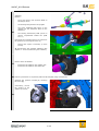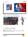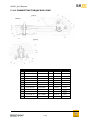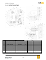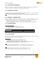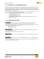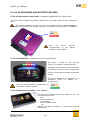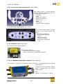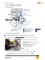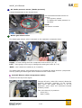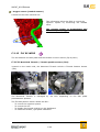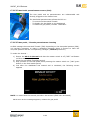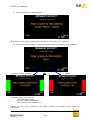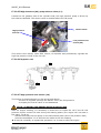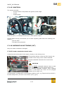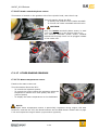
1
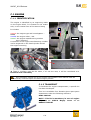
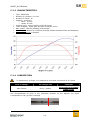
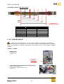
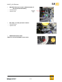
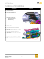
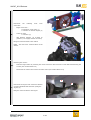
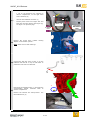
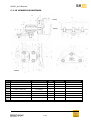
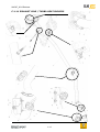
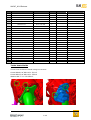
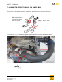
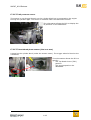
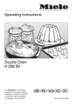
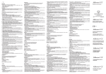
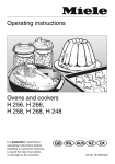
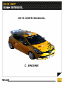
2013 USER MANUAL
C. ENGINE
98CUP_2013 Release
C ENGINE
CONTENTS
C
ENGINE
2
C.1 ENGINE
4
C.1.1 IDENTIFICATION
4
C.1.2 TRANSPORT
4
C.1.3 CHARACTERISTICS
5
C.1.4 LUBRICATION
5
C.1.5 SEALED PARTS
6
C.1.6 REMOVAL OF THE POWERTRAIN
9
C.1.7 REFITTING OF THE POWERTRAIN
13
C.1.8 CONNECTING TORQUE ROD YOKE
14
C.1.9 ENGINE MOUNTINGS
15
C.1.10 GEARBOX MOUNTINGS
16
C.1.11 EXHAUST LINE / TURBO HEAT SHILEDS
17
C.1.12 WATER CIRCUIT BUCKLE ON WATER BOX
19
C.2 POWERTRAIN MANAGEMENT
20
C.2.1 OPERATING PRINCIPLE
20
C.2.2 STARTING
21
C.2.3 DECELERATION CUT-OFF
21
C.2.4 SHIFTING STRATEGIES
22
C.2.5 BATTERY VOLTAGE
22
C.2.6 ENGINE / GEARBOX MAP
22
C.2.7 COOLING FANS
22
C.2.8 COLD START
22
C.2.9 OPERATION IN DOWNGRADED MODE
23
C.2.10 ENGINE PROTECTION
23
C.2.11 ELECTRONICS AND ELECTRIC DEVICES
24
C.2.11.1 ELECTRONICS CONTROL UNIT : COSWORTH SQ7DIRST 01E-501070-RST 24
C.2.11.2 DASHBOARD : COSWORTH ICD 01D-032954-RST
24
C.2.11.3 ELECTRONIC FUSE BOX : XAP_CBNT98
24
C.2.11.4 STEERING WHEEL SWITCH PANEL : XAP_STER98
25
C.2.11.5 FACIA SWITCH PANEL : XAP_SWT98
25
C.2.11.6 MASTER RELAY : XAP_RELAY
25
C.2.11.7 GEARBOX SHIFTING ACTUATOR: XAP_ESHIFT98
25
C.2.12 AIR INTAKE / EXHAUST
26
C.2.12.1 PRINCIPLE
26
C.2.12.2 AIR SENSORS AND ACTUATORS
26
C.2.13 FLY BY WIRE
28
C.2.13.1 MOTORISED THROTTLE / THROTTLE POSITION SENSOR (TPS)
28
C-2
98CUP_2013 Release
C.2.13.2 GAS PEDAL POTENTIOMETER SENSOR (PPS)
C.2.13.3 GAS PEDAL / THROTTLE POTENTIOMETER LEARNING
C.2.14 FUEL INJECTION
C.2.14.1 PRINCIPLE
C.2.14.2 ACCESS HATCH
C.2.14.3 FUEL TOWER
C.2.14.4 LOW PRESSURE FUEL SENSOR (3)
C.2.14.5 HIGH PRESSURE (HP) PUMP ELECTRO VALVE (11)
C.2.14.6 INJECTION RAIL
C.2.14.7 HIGH PRESSURE FUEL SENSOR (13)
C.2.15 IGNITION
C.2.16 VARIABLE VALVE TIMING (VVT)
C.2.16.1 INTAKE CAMSHAFT SOLENOID VALVE
C.2.16.2 INTAKE CAMSHAFT PHASE SENSOR
C.2.17 OTHER ENGINE SENSORS
C.2.17.1 WATER TEMPERATURE SENSOR
C.2.17.2 OIL PRESSURE SENSOR
C.2.17.3 CRANKSHAFT PHASE SENSOR (TDC OR S MOT)
C-3
29
29
31
31
31
31
31
32
32
32
33
33
33
34
34
34
35
35
98CUP_2013 Release
C.1 ENGINE
C.1.1 IDENTIFICATION
The engine is identified by an engraving made
on the engine block. It is located on the intake
side, on the vertical face of the starter fitting
B
It includes:
C
Area A: the engine type and homologation :
M5MA
Area B: the engine index : 400
Area C: the engine manufacturing number
Here “P000xxx”
A reminder of the engine manufacturing number
is also engraved on the head cylinder behind
the engine mounting
A
Starter
Gearbox
These 2 numbers must be the same, if it’s not the case, it will be considered as a
technical non conformity
Any procedure carried out on the engine not included in this manual must be
performed by a Renault Sport accredited engine partner.
C.1.2 TRANSPORT
To facilitate the engine transportation, a specific kit
has been developed.
This kit is available from Renault Sport spare parts
department under the following reference:
8201 400 360
NOTE : This kit is mandatory in case of engine
shipment to ORECA Magny Cours or to
RENAULT SPORT
C-4
98CUP_2013 Release
C.1.3 CHARACTERISTICS
Type: M5MA 400
Number of cylinders: 4 in-line
Number of valves: 16
Capacity: 1618 cm3
o Bore : 79.7mm
o Stroke : 81.1mm
Injection type : direct injection (HP fuel pump)
Turbo charged ( waste gate and pop-off electro valve)
Max. power: 162 kW (220bhp) at 6,000rpm
Max. torque: 280Nm at 4.750rpm (average 270N.m between 2500 and 6000rpm)
Max. engine speed: 6,500rpm
C.1.4 LUBRICATION
To prevent any oil surge, it is essential to drive with a minimum of 4.5 Liters
First oil change
Oil change rate
Lubricant
After 500km
Every 1,000km
Elf Excellium NF 5W40
MANDATORY
The recommended oil level is the maximum position on the dipstick (H) which
corresponds to 4.2L (oil filter included)
C-5
98CUP_2013 Release
OIL LEVEL position (oil filter filled)
1
2
3
4
LOW
Level
5
6
Level
0 : Low level
1
2
3
4
5
6 : high level
Position (mm)
0
7
15.7
21.8
27.5
32.5
38
= HIGH Level =
recommanded level
Oil quantity (L)
2.5
2.8
3.2
3.5
3.8
4.0
4.2
C.1.5 SEALED PARTS
The engine has sealed parts. The presence of these sealed parts is mandatory.
No procedure may be carried out on the engine without a representatives of Renault
Sport (Scrutinneers, technical responsible and official engine Tuner ORECA MAGNY
COURS)
TOTAL = 9 Seals
-
Timing cover
2 drilled screws
1 plastic seal
Exhaust camshaft
actuator
(Not plugged!!)
-
Turbo upstream pipe and Waste gate lung screw
1 drilled waste gate screw
1 drilled Turbo upstream pipe screw
1 steel seal
View from exhaust side
C-6
98CUP_2013 Release
-
Turbo charger clamp
1 drilled clamp
1 steel seal
Turbo
charger
heat shield
View from exhaust side
-
Oil sump
1 drilled screw (head and last threads)
1 plastic seal
Cylinder block
/ lower part
Oils sump
View from intake side
-
Waste gate hoses
2 x 2 drilled clamp
2 plastic seals
Waste gate EV
Hose coming from
the airbox
Waste gate EV : 1 seal on
hoses between the drilled
clamps
-
-
Waste gate
lung
Pop off valve
2 drilled screws
1 plastic seal
Pop off
valve
C-7
Turbo exit hose (before
Turbo air cooler)
98CUP_2013 Release
-
Manifold Pressure sensor (downstream of
the motorised throttle)
1 drilled screw
Motorised
1 plastic seal
throttle
body
-
-
Air temp + boost pressure sensor
1 drilled screw
1 plastic seal
ORECA Electronic TAG
Fitted on a head cylinder cover scew
C-8
98CUP_2013 Release
C.1.6 REMOVAL OF THE POWERTRAIN
Operations
Pictures
1 - Disconnect the battery
2 - Remove the 2 driveshafts nuts
2
4
3
Remove the air intake circuit :
3-
-
1
Air box and its support (1)
Upstream hose (2)
dowstream hose (3)
4 - Raise the vehicle.
5 - Remove the front bumper and headlights
Remove the gearbox cooling circuit : 2 hoses
6 - to the cooler
1
Remove the upper plastic crossbeam (1)
7 - Attach the coolers to the engine, using plastic
clips or straps.
2
Remove the front crossbeam (2) (gearbox
8 - cooler remains fitted) and the 3 front air ducts
(3)
3
C-9
98CUP_2013 Release
1
Disconnect
connectors:
the
following
front
loom
-
Engine cooler Fan :
2 connectors on the relay (1)
1 connector on the Fan engine (2)
-
Turbo air cooler
1 connector (3)
-
XAP Gearbox actuator (4) if fitted on
gearbox (+12v supply and red connector)
9-
3
2
Bring all connectors back to the chassis
NOTE : the front loom remains fitted on the
chassis
4
Removing the coolers :
10-
-
Drain the engine water by removing the cooler lower hose and remove the cooler after disconnecting the
2 hoses (fan remains fitted on it)
-
Disconnect the 2 hoses and remove the turbo cooler (fan remains fitted on it)
8
5
11-
Disconnect the engine loom connector situated
on engine bulkhead left hand side (facing the
engine) (5)
Bring the connector back to the engine.
Figure 1
C-10
98CUP_2013 Release
Disconnect the starter/alternator power loom :
-
1 nut on the breakout box (situated in
driver’s compartment, on the right hand
side of the ECU) (6)
7
6
-
Unscrew the bulkhead connector (7)
-
Pull the power loom from engine side and
bring the connector back to the engine (8),
see figure 1 on previous page
12-To engine
starter / alt
To chassis
loom
13-
Remove the clutch slave cylinder
adapter on the master cylinder
+12v from
XAP master
relay
feeding
Note: Watch out for fluid discharge.
Unscrew the fuel pipe union, at the ”T” on the
14- bulkhead side and fit a cap on both sides to
protect the fuel hose from dirtiness
1
15-
Disconnect the lambda sensor (1) and bring the
corresponding chassis connector back to
driver’s compartment
Remove the exhaust line clamp before
intermediate line (2)
the
C-11
2
98CUP_2013 Release
Subframe
Remove :
1
-
The 2 anti roll bar rods (let them fitted on
the damper strut)
-
The steering ball joint from the uprights
-
The lower wishbones ball joints on the
uprights (let the wishbones fitted on the
subframe)
-
The steering intermediary shaft (access in
driver’s compartment behind the pedal
box) (1)
16-
Disconnect the connecting torque rod yoke from
the gearbox by removing the screw (2)
-
2
Remove the square if necessary (2 more
screws)
Then Remove the complete subframe (See
chapter D : Front axle/Removing the subframe)
Remove the 2 driveshafts:
17- -
Extract the driveshaft on the gearbox side.
Extract the driveshaft on the wheel side.
18- Place the powertrain on a hydraulic plate and lift it slightly using wood spacers
Separate the gearbox mounting by removing
the screw (1)
If necessary , remove
the support on the
gearbox (4 screws)
1
19-
C-12
98CUP_2013 Release
Separate the engine mounting when removing the
screw (2)
19-2
A
20- Take out the powertrain lowering the hydraulic plate.
NOTE : to lift the power train, fit the adapted engine lift brackets
- 1 front bracket on head cylinder near the engine mounting (A)
- 1 specific rear bracket between upstream turbo pipe and engine, fitted on head cylinder
Rear bracket :
8201 428 360
C.1.7 REFITTING OF THE POWERTRAIN
Carry out the previous operations in reverse order.
When refitting the powertrain, it is important to comply with the following
positioning procedure for the powertrain in order to guarantee the operational
clearances required for the driveshafts.
C-13
98CUP_2013 Release
C.1.8 CONNECTING TORQUE ROD YOKE
gearbox
subframe
gearbox
N°
Part
Ref
Qty
1
Torque rod yoke
8201354335
1
2
Ball joint
7711160476
1
3
Lower spacer
8201354569
1
4
Upper spacer
8201354558
1
5
Snap ring
7711160477
1
6
Silent block
7711160043
2
7
Washer M12
7711156931
2
8
Screw M12-90
7703602201
1
9
Triangle bracket
8201368206
1
10
Screw M12-85
8201368275
1
105 N.m
11
Screw M8-20
7711128280
2
30 N.m
12
Washer M8
7711156945
2
C-14
Torque
thread
105 N.m
Cooper
grease
Cooper
grease
LOCT 243
(blue)
98CUP_2013 Release
C.1.9 ENGINE MOUNTINGS
N°
Part
Ref
Qty
Torque
thread
1
Engine/engine mounting
8201355219
1
2
Engine mountings interface
7711167027
3
1
100 N.m
LOCTITE 243 (blue)
Screw M10-30
7711156933
7
62 N.m
LOCTITE 243 (blue)
62 N.m
LOCTITE 243 (blue)
105 N.m
Cooper grease
4
Contact washer Ø10
7711156944
8
5
Engine/engine mounting shim
8201362862
1
6
Screw M10-90
7711127847
1
7
Engine/chassis mounting
8201354703
1
8
Silent bloc
7711160043
2
9
Washer Ø10
7703053341
3
10
Screw M12 - 98
7711167029
1
11
Washer Ø12
7711156931
1
C-15
98CUP_2013 Release
C.1.10 GEARBOX MOUNTINGS
CHASSIS
CHASSIS
GEARBOX
CHASSIS
GEARBOX
N°
Part
Ref
Qty
1
Gearbox/gearbox mounting
8201371034
1
2
Silent bloc
7711160043
2
3
Screw M10-20
7711128989
4
Torque
thread
70 N.m
LOCTITE 243 (blue)
4
Contact washer Ø10
7711156944
7
5
Gearbox/chassis mounting
8201360377
1
6
Gearbox mountings interface
7711167027
1
100 N.m
LOCTITE 243 (blue)
7
Screw M12 - 98
7711167029
1
105 N.m
Cooper grease
8
Washer Ø12
7711156931
1
9
Screw M10 -35
7711051273
3
62 N.m
LOCTITE 243 (blue)
C-16
98CUP_2013 Release
C.1.11 EXHAUST LINE / TURBO HEAT SHILEDS
therese1
C-17
98CUP_2013 Release
N°
Part
Ref
Qty
Torque
Thread treatment
1
Turbo exit line
82 01 368 925
1
2
Locknut M10
14094 4P100
1
63 N.m
Without
3
Screw M10-26.5
14069 1KC0A
2
63 N.m
Without
4
Turbo / turbo exit line seal
5
14445 1KC0A
1
Screw M10-20
77 03 002 854
1
6
Silent bloc F1
82 01 142 258
1
50 N.m
LOCTITE 222 (purple)
7
Screw M8-30
77 03 002 794
1
24 N.m
Without
8
Screw M6-20
77 03 602 282
2
10 N.m
Without
62 N.m
Without
62 N.m
Without
24 N.m
Without
9
Clamping Ø83
82 01 369 110
2
10
Lambda sensor
82 00 420 670
11
Intermedary line
82 01 403 325
1
1
12
Silent bloc F4
206 51 63 64 R
1
13
Screw M10-50
77 03 602 189
1
14
Muffler: silencer+ catalysor
82 01 409 008
1
15
Cap M18
77 03 075 076
1
16
Cooper seal Ø18
77 11 166 083
1
17
Silent bloc F7
82 00 444 058
2
18
Left support
20793 2514R
1
19
Muffler support
82 01 403 488
2
20
Screw M10-110
77 03 602 190
1
21
Sealing spacer
82 00 564 670
1
22
Left spacer
82 00 564 668
1
23
Nut M8
77 03 034 131
4
24
Screw M8-20
82 01 419 296
2
25
Contact washer M8
77 11 156 945
2
Turbo heat shields
These heat shields are fitted using inox screws
Screw M6x20 ref 8201 431 561 x3
Screw M6x15 ref 8201 431 558 x2
Washer M6 77 11 158 358 x5
C-18
98CUP_2013 Release
C.1.12 WATER CIRCUIT BUCKLE ON WATER BOX
This buckle is not directly sold as a spare part. It is built from 2 genuine references:
(13) 92 40 035 21R:
Cut the hose to only
keep the nozzle
(14) 92 41 014 55 R :
Remove the clamp
Cut the hose
Turn the hose (14) to obtain the right orientation and fit the nozzle as indicated below:
Nozzle
from (13)
C-19
98CUP_2013 Release
C.2 POWERTRAIN MANAGEMENT
C.2.1 OPERATING PRINCIPLE
COMPONENTS COMPRISING THE ENGINE AND GEARBOX MANAGEMENT SYSTEM
− Fuel circuit
Low pressure fuel pump (in fuel tank) with integrated regulator (5bars)
High pressure pump (on exhaust camshaft extremity)
Fuel pressure sensors :
o Low pressure sensor (exit of the fuel tank behind the chassis cover)
o High pressure sensor (on the high pressure rail under intake manifold)
4 Injectors
− Electronics
ECU (SQ7 Di)
XAP electronic fusebox (CBNT)
Dashboard (ICD Lite)
Switch panel on facia
Steering wheel switch panel (buttons and paddle shift kit)
XAP Master Relay
- Engine sensors / actuators
Air temperature + boost pressure sensor
Intake manifold sensor
Crankshaft phase sensor
Intake camshaft phase sensor (exhaust not used)
Intake camshaft dephaser solenoid valve (exhaust not used)
Oxygen/lambda sensor
Motorised throttle + integrated throttle position sensor (TPS)
Gas pedal position sensor (PPS)
Oil pressure sensor
Water temperature sensor
High pressure fuel pump electro valve
Pop-off electro valve
Turbo waste gate electro valve
- Gearbox sensors / actuators (see chapter D Transmission / shifting)
XAP Electric Actuator (semi-automatic shifting kit)
Barrel position sensor
Magnet power shift sensor
Barrel unlocking solenoid
− Power
4 Coils
Starter
Alternator
− Cooling
Engine water cooler + fan (2 speeds)
Turbo air-air cooler + fan (1 speed)
C-20
98CUP_2013 Release
Schematic diagram
Boost
press
Water
temp
Air
temp
Oil
press
Fuel
Low /
high
press
GB
Barrel
position
Intake
Camshaft phase
Air
Intake
press
Oxygen/lambda sensor
Facia switch panel
(engine MAP)
Gas pedal position
Cranskshaft
phase
GB Magnet power sensor
Steering wheel paddle
shift
Throttle position
Battery Voltage
ECU
Throttle motor
Intake camshaft
solenoid valve
Injectors
HP fuel pump EV
LP Fuel pump
Turbo waste gate EV
GB XAP
Electric
actuator
Turbo Engine
Pop
water
off EV fan
fan
Starter /
alternator
Coils
C.2.2 STARTING
2 possibilities to start the engine :
1) “hot start” or after an engine stalling
2) “cold start” just after putting general power supply ON
Starting is made easier if a "cold start" is performed. To make it, turn the power supply
OFF and then ON (button (1) on the facia switch panel)
the ECU will perform a "cold
start" :
- The reference position of the Motorised Throttle is higher than if the engine was
stalled before, without general power supply cut between 2 consecutive starts
- The fuel pump is controlled then, after the engine start command, it performs wall
wetting injections.
To start the engine correctly when it is cold (WaterT<50°), we stronlgy advise you to
press the “START” button (button (3) of the facia switch panel) with “IGNITION”
switched OFF (button (2) of the switch panel) during a few seconds to rise
progressively the oil pressure (oilP). You can check the “oilP” value on the
dashboard in engine diagnostic page (see chapter B-presentation)
As soon as the oilP starts growing to 0.8b, you can then flick the “IGNITION” ON and
then press “START” to start the engine.
Also, if cold starting fails, it is advisable to turn OFF the general power supply and repeat
the engine start procedure.
C.2.3 DECELERATION CUT-OFF
When the Gas pedal is fully released and the engine speed is greater than 3500rpm, the
injectors are no longer controlled. Injection is re-instated in one of the following two
cases :
- Gas Pedal position > 2%,
- Engine revs < 2500rpm
C-21
98CUP_2013 Release
C.2.4 SHIFTING STRATEGIES
Differents strategies are applied depending on gearbox shifting mode (semi-auto or
manual). Please refer to chapter D.2.9 (Gearbox shifting modes)
C.2.5 BATTERY VOLTAGE
The ECU requires a voltage with the starter activated greater than 9 volts. Below this
threshold, the battery must be charged or replaced.
In order to avoid damage to the ECU, it is not advisable to use a battery ”booster”.
C.2.6 ENGINE / GEARBOX MAP
The switch “MAP” situated on the Facia switch panel, offer the possibility to switch
between 2 mappings : DRY or WET. The differences are on the following parameters :
- Gas Pedal / throttle position law : “softer” law on WET conditions
- Shifting managemement : Blip more important during downshift on WET position
C.2.7 COOLING FANS
Turbo Air Exchanger fan
turns on if the Air Temperature is > 50°C
turns off when the Air Temperature is <48°C
Engine Water Fan
Turns ON
Turns OFF
Low speed
Water Temperature > 87°c
Water Temperature < 86°c
High speed
Water Temperature > 90°c
Water Temperature < 88°c
C.2.8 COLD START
To avoid engine damages during this phase and encourage to make a correct cold start,
the following securities have been implemented :
Boost Pressure
- No Boost Pressure when water Temperature < 30°c
the pop-off valve is fully open (pop-off : 100%)
- Partial Boost Pressure between 30°C < water Temp < 50°c (pop off : 0%)
- Maximal Boost Pressure allowed when water temp > 50°c.
VVT
- No VVT when water temperature < 55° : VVT1_pos : 100 / VVT1_tg : 0
- When Water Temperature >55°C : VVT1_pos follows strictly the VVT1_tg
RPM
Engine RPM is limited to 4500 rpm when Water Temperature < 50°c.
Engine RPM is limited to 6500 rpm when Water Temperature > 60°c.
C-22
98CUP_2013 Release
C.2.9 OPERATION IN DOWNGRADED MODE
The ECU performs a self-diagnostic from input parameters and warns the driver of an
abnormal measurement by means of an alarm on the Dashboard. The alarm is activated
on the Dashboard as soon as the fault is present. Each alarm is registered in the form of
a diagnostic code in the data acquisitions and in the bottom left position of the dashboard
(refer to chapter B-presentation).
In the event of an abnormal parameter, the ECU works in downgraded mode with a
default value for the faulty input. These values are:
Air temperature: 0°C (Richness grows to reduce performances)
Water temperature: 80°C.
Throttle potentiometer: 13deg
Gas pedal potentiometer : 0%
Intake pressure: 950 mbars (performances are degraded is the sensor sis
absent or defective)
C.2.10 ENGINE PROTECTION
Boost Pressure
- When Water temperature (waterT) > 100°c Boost Pressure decrease progressively
- When WaterT >120°c, Boost Pressure stops (pop-off valve fully open 100%)
- When Air Temperature (airT) = 60°c, the Boost Pressure Target is reduced of 6%. This
percentage progressively increase to reach :
15% when AirT = 90°
21% when AirT = 110°c
Engine Revs limiter
When Water > 100°c, the engine maximum RPM (6500 rpm) starts to decrease linearly
to reach 3500 rpm at 120°c
When WaterT > 120°c, the limiter is still 3500rpm
Igntion advance:
When Air Temperature >70°c, the ignition advance drops of 3° to progressively reach -5°
at 100°c
Fuel injection:
When Air Temperature > 60°c, the fuel injection increase from 1% to 3% (depending on
Manifold Pressure)
This percentage progressively increase to reach 2% to 8% when Air Temperature > 90°c,
still depending on Manifold pressure
C-23
98CUP_2013 Release
C.2.11 ELECTRONICS AND ELECTRIC DEVICES
C.2.11.1 Electronics Control Unit : COSWORTH SQ7DiRST 01E-501070-RST
The ECU controls engine and gearbox operations. It is fitted under the facia, passenger
side
It is strictly forbidden to open the ECU. The Cosworth security labels must be
present. If these labels are missing, this can be considered a technical non compliance.
Only
one
sticker
allowed
corresponding to the lastest
software / Map update
C.2.11.2 Dashboard : COSWORTH ICD 01D-032954-RST
This dash is fitted on the steering
column (3 possible vertical positions)
It displays on 8 screens all the necessary
information for driver and for diagnostics
It also incorporates the datas acquisition
system
All alarms displayed are classified in 2
categories (refer to chapter B –
presentation)
Only one sticker allowed corresponding to
the lastest software update
C.2.11.3 Electronic Fuse Box : XAP_CBNT98
This fuse box manages the power supply of all +12v
consumers of the car
- ECU
- Starter excitation
- VVT actuator
- Wheel speed sensors
- …etc
PINOUT indicated in chapter F - Wiring and electrical
equipment)
C-24
98CUP_2013 Release
C.2.11.4 Steering wheel switch panel : XAP_STER98
This switch panel is fitted between
steering wheel and steering wheel Hub.
It allows the activation of :
- pit limiter
- lights
- windscreen washer
- Gb barrel unlocking
- Page change
- Wiper
- Free button
- Gearbox shifting (paddles)
C.2.11.5 Facia switch panel : XAP_SWT98
This second switch panel is fitted
directly in the central area of the
facia
It allow the activation of :
- Masterswitch (ON/OFF)
- Ignition
- Starter excitation
- Manual fuel pump
- Engine map (DRY/WET)
- …etc
C.2.11.6 Master relay : XAP_Relay
This relay is fitted near the battery.
It allows the supply of :
- the chassis loom (CBNT Supply)
- starter / alternator / XAP gearbox actuator
C.2.11.7 GEARBOX SHIFTING ACTUATOR: XAP_ESHIFT98
This actuator is fitted on the gearbox clutch casing ant is articulated with the manual
selection axis.
It allows the semi-automatic shifting
mode in parallel with the manual
shifting mode.
See
chapter C-Transmission / shifting
C-25
98CUP_2013 Release
C.2.12 AIR INTAKE / EXHAUST
C.2.12.1 Principle
ENGINE
EXHAUST VALVES (8)
INTAKE VALVES (8)
INTAKE
MANIFOLD
EXHAUST
MANIFOLD
MOTORISED THROTTLE + TPS
POP
OFF
E.V.
WASTE
GATE
EXHAUST
GAZ
T
C
AIR EXHANGER + FAN
AIR
BOX
AMBIENT AIR INTAKE
ATMOSPHERIC PRESSURE AIR
WASTE GATE ELECTRO VALVE
INTAKE COMPRESSED AIR
MANIFOLD AIR PRESSURE SENSOR
EXHAUST GAZ
BOOST PRESSURE SENSOR
+ AIR INTAKE TEMP SENSOR
TURBO CHARGER
C COMPRESSOR
T TURBINE
OXYGEN SENSOR
C.2.12.2 Air sensors and actuators
- Air intake temperature sensor + boost pressure sensor = 1 Sensor
These 2 functionalities are included in 1 sensor fitted on the plastic upstream hose to
the throttle body
This information allows the ECU to control:
-
The injection system.
The air temperature and boost pressure on
the display.
The Turbo air exchanger fan when the
temperature reaches 50°C
The Waste gate Electro valve
The pop off electro valve
NOTE :
This sensor is sealed
-
To fit it, the original screw (drilled on the head) is a 8201 415 686
-
In case of damage of the thread it’s possible to fit the new
reference 8201 431 863
C-26
98CUP_2013 Release
- Air intake pressure sensor (Intake pressure)
Located downstream to the throttle hose
This information allows the ECU to
control:
- The injection system.
- To display the intake pressure on
the dash.
NOTE :
This sensor is sealed
- Waste gate electro valve
The Waste gate electro valve is situated on the upstream compressor hose.
A’
A
B
B’
Supply : 1 hose coming from the compressor exit to the EV (A > A’)
Exit : 1 hose going to the lung to manage the waste gate valve (B > B’)
NOTE : the 2 hoses are sealed (A, A’, B and B’)
The Waste gate electro valve allows the ECU to regulate the boost pressure (compressor
side by opening the waste gate valve situated on the Turbine side.
POP OFF Electro valve (overpressure valve)
Located on the top of the engine
The pop off valve, under ECU control, allows the
pressure discharge upstream of the throttle
body when the Boost pressure is at its
maximum value when the motorised throttle
suddenly closes.
This valve has only 2 positions:
- Close (0%)
- Open (100%)
C-27
98CUP_2013 Release
- Oxygen sensor (Lambda sensor)
Located on the turbo exhaust exit
This information allows the ECU to control the
injection system by monitoring the lambda
value.
The Oxygen sensor is proportional and
must always be plugged
C.2.13 FLY BY WIRE
The link between the Gas pedal and the throttle is 100% electric (Fly By Wire)
C.2.13.1 Motorised Throttle / Throttle position sensor (TPS)
Located on the intake side, the Motorised Throttle include a Throttle Position Sensor
(TPS)
The Motorised Throttle is managed by the ECU depending on the Gas pedal
potentiometer position
The Throttle position sensor allows the ECU :
- To control the injection system.
- To control the VVT
- To display the throttle position on the dashboard
- To make the throttle / gas pedal calibration
C-28
98CUP_2013 Release
C.2.13.2 Gas Pedal potentiometer sensor (PPS)
The Gas pedal and its potentiometer are indissociable and
directly plugged to the chassis loom.
The Gas Pedal potentiometer allows the ECU to:
- To control the Motorised Throttle
- To display the Gas Pedal on the dashboard
- To make the gas pedal / throttle calibration
C.2.13.3 Gas pedal / Throttle potentiometer learning
As ECU manage the motorised Throttle (TPS) depending on the Gas pedal position (PPS),
it’s regularly necessary to make a calibration between these 2 sensors to learn the
min/max position and the corresponding voltages. (Autocal procedure)
To make the Autocal :
1) Ensure the GB is in Neutral and that the master switch is off (“OFF” red Button
on Facia switch panel)
2) Press the Gas pedal (complete stroke)
3) Stay pressed on the Gas pedal while pressing the master switch on (“ON” green
button on the facia switch panel)
4) Just after the dashboard has started and is initialised, the following screen
appears
NOTE : it means that the Autocal procedure has started (FBW learn activated)
As soon as the message appears, release the gas pedal
C-29
98CUP_2013 Release
5) Then the following screen appears :
Follow the instructions: pump Gas pedal twice (full stroke) then release it.
6) The calibration procedure is being performed when the following screen appears:
2 possible results: “success “
OR
“failed”
If the FBW learn failed, check:
- The Motorised Throttle
- The Gas Pedal potentiometer
- The chassis and/or engine loom
Despite of this, if the Autocal is still NOK, contact your Renault Sport Technical
interlocutor.
C-30
98CUP_2013 Release
C.2.14
FUEL INJECTION
C.2.14.1 Principle
Low pressure side (5 bars) : parts 1>10
10 : low pressure fuel pump
3: Low pressure sensor
9: degassing
7: fuel sampling
12
High pressure side (>20 bars) : parts 11>13
13
11
11: high pressure pump
12: injectors + rail
13: high pressure sensor
C.2.14.2 Access Hatch
C.2.14.3 Fuel tower
The fuel tower is situated directly in the fuel tank. It contains:
- A low pressure fuel filter
- A low pressure pump
- A fuel pressure regulator
The fuel pump is managed by the ECU and is regulated by the
regulator at 5 bars*
C.2.14.4 Low pressure fuel sensor (3)
This sensor is situated on a “T” union just after the fuel tower exit and allows
displaying the fuel pressure on the dashboard.
C-31
10
98CUP_2013 Release
C.2.14.5 High Pressure (HP) pump electro valve (11)
Located on the gearbox side of the cylinder head, the high pressure pump is driven by
the exhaust camshaft. The electro valve is situated above the HP pump.
Electro Valve
High pressure
fuel exit
Low pressure fuel
arrival (5b)
A
This electro valve allows, under ECU control, to maintain and permanently regulate the
high fuel pressure inside of the fuel rail.
C.2.14.6 Injection rail
13
12
A
11
C.2.14.7 High pressure fuel sensor (13)
This sensor is situated directly on the HP rail and allows:
- the ECU to regulate (through the Electro valve) the fuel pressure
- to display the fuel HP value on the dashboard
NOTE : STARTING THE ENGINE AFTER A REFFITTING
After an engine refitting, it’s necessary to bleed the air inside the rail if the HP fuel
pressure doesn’t exceed 10 bars during the starting phase (The engine will not start in
this case). To do so:
- Activate manually the fuel pump on the facia switch panel (5b on low pressure side)
- Unscrew the adapter “A” to allow the air inside of the rail escaping
It may be necessary to repeat this operation 2 or 3 times to start the engine
C-32
98CUP_2013 Release
C.2.15 IGNITION
The system includes:
- The ECU which incorporates the ignition power stage.
- 4 coils
- 4 spark plugs.
N°1
N°4
N°2
N°3 : Under
turbo exit hose
Each Coil (Pin 1) is managed directly by an ECU ignition output.
Renault Sport strongly recommend you to check regularly (after each race meeting) the
state of :
- The coil stem
- The spark plug electrode
C.2.16 VARIABLE VALVE TIMING (VVT)
Only the intake camshaft if managed
C.2.16.1 Intake camshaft solenoid valve
Located on the timing side of the engine, directly on the timing cover
This actuator allows, under the ECU Control, the
variable valve timing of the intake camshaft
Exhaust camshaft solenoid valve must not be
used
CAUTION
Only the intake camshaft solenoid valve is used
(only one connector on the engine loom for it).
The exhaust camshaft solenoid valve situated
above is still fitted but must not be plugged
instead of the intake one.
This parameter corresponds in the acquisition table to VVT1_tg (Target sent by the ECU)
If water temp<55°C, the VVT is not driven (VVT1_tg=0)
C-33
98CUP_2013 Release
C.2.16.2 Intake camshaft phase sensor
This sensor is located on the gearbox side of the cylinder head, near the oil cap.
This information allows the ECU
- To specify the position of the intake camshaft.
- To control the intake camshaft solenoid valve
CAUTION
Only the intake camshaft phase sensor is used
(only one connector on the engine loom for it).
The exhaust camshaft phase sensor situated
behind the HP pump must not be plugged instead
of the intake one.
C.2.17 OTHER ENGINE SENSORS
C.2.17.1 Water temperature sensor
Fitted to the water outlet unit.
This information allows the ECU:
- To control the injection system.
- To control the engine cooling fan activation when the
temperature reaches 87°C first speed) and 90°C
(second speed)
- To display the water temperature on the dashboard
NOTE :
The engine water temperature sensor is particularly important during engine cold start
because it restricts the VVT, the Boost Pressure and the RPM limiter. Please refer to page
C-18 and respect the engine warm-up procedure rigorously.
C-34
98CUP_2013 Release
C.2.17.2 Oil pressure sensor
This sensor is not plugged directly on the cylinder block but is connected to the engine
through an hydraulic pipe. The sensor is situated under the Motorised Throttle.
This information allows the ECU to display the
oil pressure on the dashboard.
C.2.17.3 Crankshaft phase sensor (TDC or S mot)
Located on the cylinder block (under the starter motor). The trigger wheel is fitted to the
crankshaft
This information allows the ECU to
specify:
- The Top Dead Centre (TDC)
position.
- The engine speed on the
dashboard
C-35