1
Operator Manual FCM-II
Contents
This Operator Manual serves two goals. The first is to give the user or operator a quick overview of all safety issues
of the FCM-II machine. The second is to give the operator a quick overview of the basic actions to operate the FCMII machine. For more detailed information regarding the operation or servicing please refer to the USER and SERVICE
manuals of the FCM-II machine.
Note:
These cards are based on FCM-II Controller Software Versions 5.12 and 5.2
en
Card Contents:
Card 1-2
-
General Safety Rules
Card 3
-
Work-Flow
Card 4-5
-
Layout of FCM-II System Indicators and Switches
Card 6
-
Pre-Start Operations
Card 7
-
Switch-On Procedures
Card 8
-
Continue Running an Active Order
Card 9
-
Error Handling
Card 10
-
Stop Procedures
Card 11
-
Entering a New Order
Card 12-13 -
Conventional Batch Changeover
Card 14
-
Rolling Batch Changeover
Card 15
-
Shutdown Procedure
Card 16
-
Quick Reference Card Human Interface - Main Menu
Card 17
-
Quick Reference Card Human Interface - Maintenance/Service Functions
Card 18
-
Quick Reference Card Human Interface - BVM
Card 19
-
Quick Reference Card Human Interface - MIS Functions
4022 591 94512
01.02
Appendix A -
Philips
Electronic Manufacturing
Technology
Quick Reference Cards Fast Product Changeover
General Safety Rules
1
General:
For the correct and safe use of the FCM-II system, both the OPERATING and SERVICE personnel should follow
generally accepted safety procedures. In addition, they must comply with the safety precautions as specified in this
manual. Where necessary special warning and caution statements are used throughout this manual. Moreover, all
warning and caution statements present on any sticker on the FCM-II system are explained in this chapter.
Personnel qualification:
Operation, adjustment, maintenance and repair of the FCM-II system may only be carried out by trained and qualified personnel who are aware of the hazards involved. The following training levels are defined:
■
Operator level: Official Philips training course or training received by a qualified maintenance engineer.
■
User or Supervisor level: Official Philips training at one of the official Philips Training Centres.
■
Maintenance or Service level: Official Philips training at one of the official Philips Training Centres.
Caution and Warning Statements:
Caution!
TO URGE ATTENTION IN ORDER TO PREVENT DAMAGES TO EQUIPMENT, FURTHER
DESCRIBED WITHIN THIS FRAME.
Warning!
TO URGE ATTENTION IN ORDER TO PREVENT PERSONAL INJURIES OR DANGEROUS SITUATIONS, FURTHER DESCRIBED WITHIN THIS FRAME.
01.02
en
Safety standards:
The safety of the FCM-II system is in accordance with following CE directives:
■
Machine directive 89/392/EEC including amendments
■
Low Voltage directive 73/23/EEC including amendments
■
EMC directive 89/336/EEC including amendments.
To be handled by the FCM-II system, products are to be inserted at the FCM-II’s run-in section opening
and they will leave it via its run-out section opening. Moreover, components to be placed by the FCMII system are picked up from the attached component feeders via the component pick-up area opening. Because of this, the run-in and run-out section openings as well as the component pick-up area
openings are to be considered as functional items of the FCM-II.
4022 591 94512
Warning!
IT IS NOT ALLOWED TO TOUCH ANY PART IN THE RUN-IN SECTION, THE RUN-OUT
SECTION OR THE COMPONENT PICK-UP AREA OPENING WHENEVER THE FCM-II MACHINE
IS RUNNING!
Since the FCM-II is designed for operation in a flowline, full mechanical safety in accordance with the above mentioned standards is only guaranteed when openings of the run-in and run-out sections are covered by the preceding
and succeeding equipment in the flowline. Therefore, the FCM-II system should not be operated as a standalone machine.
Operator Manual FCM-II
General Safety Rules
2
Caution and Warning Stickers on the FCM-II
Category
Meaning
WARNING
Danger.
High voltage!
WARNING
Danger.
Moving parts, crushing risk!
WARNING
Danger.
Rotating parts, risk of drawing in!
WARNING
Danger.
Class I laser product, risk of laser
radiation!
Do not enter the laser source area
with reflective material, as this may
expose you to reflected laser radiation!
CAUTION
Very sensitive part, handle with care.
01.02
en
Pictogram
4022 591 94512
Noise Level:
Average sound-pressure level measured at 3 operator positions at
height 1.5 m and distance 1 m
≤ 79 dB(A)
Sound pressure at operator’s position
≤ 78 dB(A)
Average environmental noise level during measurement
53 dB(A)
Liability:
Philips shall not be liable for any costs, damages or personal injuries if the FCM-II system is not used according to the
safety rules given in this paragraph.
Operator Manual FCM-II
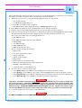
Work-Flow
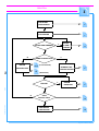
3
PRE-START
OPERATIONS
6
SWITCH ON
PROCEDURE
7
ENTER
A NEW
ORDER
Y
ENTER NEW ORDERS?
11
N
N
Y
SAME PRODUCTION?
BATCH
CONTINUE
12-13 (Conventional)
RUNNING THE
CHANGEOVER
CURRENT ORDER
en
14
(Automatic)
ERROR?
01.02
8
Y
ERROR
HANDLING
9
N
N
STOP
PRODUCTION?
10
4022 591 94512
Y
SHUTDOWN
PROCEDURE
15
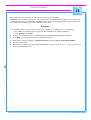
Operator Manual FCM-II
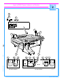
Layout of FCM-II System Indicators and Switches
4
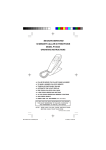
Locations of the various switches and indicators. Please refer to the figure on Card 5.
1 - Warning lights:
A 3 colour lamp pole, displaying the following statuses of the FCM-II:
• WHITE
→
Idle mode.
• BLUE
→
Error condition.
• GREEN
→
Running mode.
2 - Human Interface:
The part of the FCM-II where the user communicates with the system via a monitor
and keyboard.
3 - Main power switch:
With this switch the main power is switched on.
4 - Main power
phase indicator
Light-green lamp (LED), indicating if the main power is switched on and all 3 phases are
OK.
5 - Servo power button:
With this button the servo power is switched on.
6 - Servo power indicator:
Dark-green lamp, indicating if the servo power is switched on.
7 - Emergency stop switches With these switches the machine can be stopped immediately causing a stop of all
servo movements.
9 - Safety caps:
All safety caps mounted on positions where no Pick & Placement Modules are present,
are equipped with interlock switches. These switches inhibit a servo movement when
opened.
10 - Main Air Valve:
Three position valve for opening (pos. III) and closing (pos. II) the main air supply. Also
for releasing the air from the FCM-II (pos I).
11 - Gauges:
Gauges indicating the main vacuum of -0.77 bar (Gauge A) and air pressures of
2.6 bar (Gauge B) and 5.7 bar (Gauge C).
12 - ESD Earth Facility:
Connecting points for ESD safety equipment (e.g. bracelet).
13 - BVM Monitor:
Monitor of the Board Vision Module which display images taken by the BVM Camera
(e.g. fiducials and badmarks)
4022 591 94512
01.02
en
8 - Transport cover switches All transport covers at the run-in and run-out section are equipped with interlock
switches. These switches inhibit a servo movement when opened.
Operator Manual FCM-II
Layout of FCM-II System Indicators and Switches
5
10
11
I
II
III
A B C
1
0
1
2
13
01.02
en
9
7
12
4022 591 94512
Emergency Stop
8
ESD
EARTH
FACILITY
Emergency switch panel
on run-in section
12
ESD
EARTH
FACILITY
3
4
8
5
Main switch
Main switch panel on
run-out section
6
Servo power on
7
Emergency Stop
FCM5038a.fm
Operator Manual FCM-II
Pre-Start Operations
6
Before switching on the FCM-II, carry out the following actions:
1.
Check cleanliness in and around the FCM-II:
• No PCBs present in the workarea.
• No waste components in the transport area.
• No waste components on the feeder positions of the feeder trolley.
• All waste bins empty.
• All dump position containers empty (when using Wide Vision Modules, also the containers mounted on the
side of the Camera Unit).
• Clean FCM-II workarea (including production floor).
2.
Check for unsafe situations in and around the FCM-II:
• All rear covers of the Pick & Placement Modules must be present.
• On positions where no Pick & Placement Modules are mounted, safety caps must be present (Card 5, item 9).
• At the run-in and run-out sections, safety covers must be present.
• Door to the Electrical Controller must be closed.
• Cover on Air Supply & Vacuum Unit must be present.
• No persons or objects must be in the user’s way, thus preventing him from accessing the various parts of the
FCM-II workarea.
4022 591 94512
01.02
en
Warning!
BEFORE SWITCHING THE MACHINE ON, MAKE SURE THAT ALL PRE-START OPERATIONS AS
MENTIONED ABOVE ARE CARRIED OUT!
Operator Manual FCM-II
Switch-On Procedures
7
en
To start-up the system, proceed with the following actions (Card 5 for location of indicators and switches):
1.
Are all Pre-start actions done? If not, go to the Pre-start Operations (Card 6).
2.
Switch on the compressed air by turning the Main Air Valve (10) in position III.
3.
Read the Pressure Gauges (B) and (C).
4.
Are the pressures OK? (Gauge B: 2.6 ± 0.1; Gauge C: 5.7 ± 0.1 bar). If not adjust the air pressures to the correct
values.
5.
Switch on the main power by turning the Main Switch (3).
6.
Is the light-green Main Power Phase-indicator (4) on? If not, switch off the main power and contact Maintenance.
7.
Wait for complete system startup until Main Screen appears on the Human Interface and hour glass disappears.
8.
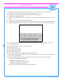
Is there an error message displayed? If so, read the help information, and contact Maintenance if necessary.
9.
Read Vacuum Gauge (A).
10. Is vacuum -0.77 ± 0.04 bar? If not, contact Maintenance.
11. Close transport covers.
12. Close safety caps (if present).
13. Lower all Placement Modules.
14. Release all emergency stops.
01.02
15. Switch on the servo power by pushing the Servo Power Button (5).
16. Is the dark-green Servo Power Indicator (6) on? If not, check again if all covers are properly closed. If this does
not work, contact Maintenance.
17. Has the complete emergency circuit been checked? If not, check if the servo power switches off after:
• Raising each individual Placement Module.
• Opening each individual transport cover.
• Opening each individual safety cap (if present).
• Pushing each individual emergency stop.
4022 591 94512
If the emergency circuit is not OK, stop and contact Maintenance.
Operator Manual FCM-II
Continue Running an Active Order
8
This card describes the actions which must be done in order to continue a production run after a previous FCM-II
shutdown, batch changeover or temporary production stop. To prepare the system for a batch change (different
product and/or new Order) please Card 12-13 or Card 14. For detailed information refer to the User Manual FCM-II.
Carry out the following actions:
Make sure that the steps described in Card 6 and Card 7 are carried out.
2.
Check if the Feeder and Nozzle setup has not been changed since the last production stop. This can be done
using the FCM-II Line Setup Listing.
3.
Check for the availability of the necessary amount of component reels. This can be done using the FCM-II
Requirements Listing.
4.
Make sure that production boards are present in front of the FCM-II.
5.
Press <F5> on the Human Interface keyboard. The “Production-Start” dialogue will appear.
6.
Select [Start] or press <F5>. If the system was previously shut down, the FCM-II will now home the Transport
system, the individual Pick & Placement Modules and BVM (if enabled). Furthermore each Pick & Placement Module will calibrate its vacuum.
7.
Is there an error message displayed? If so, read the help information, and contact Maintenance if necessary.
8.
If no error messages were displayed, the FCM-II starts production, and boards will be admitted into the transport
area as soon as the first board is available on the preceding module.
4022 591 94512
01.02
en
1.
Operator Manual FCM-II
Error Handling
9
This card describes the actions to be taken in case an error occurs during running of a product. For more detailed
information of possible errors please refer to the Operator and Service manuals.
1.
Whenever a process error occurs, the following symptoms can be seen and noticed:
• The machine will stop.
• The BLUE warning light will go on.
• An audible sound will occur (if configured).
• The FCM-II Machine Status display will change to ERROR (Highlighted in red).
2.
Press <F3> in the Main Screen. The “Production-Error recovery” dialogue will appear.
3.
Read the error message displayed (and if applicable, look at the image on the video monitor).
4.
Is the error message clear? If not, select the error with the pointer (the error will be highlighted) and press <F1>.
This will activate the Help Screen which will give you more detailed information about the error.
The process errors which may occur during production are:
• Miss SMD after pick.
• Lost SMD before align (only when using a WVM).
• Misalign SMD.
• Lost SMD after align.
• Retain SMD after place.
• SMD lost due to power down.
They are mostly caused by the following:
• Empty feeder.
• Too many empty pockets in tape.
• Wrong nozzle type.
• Wrong component type.
en
• Dirty nozzle.
• Feeder trolley not mounted properly.
• Push rod not working properly (contact Maintenance).
• Bad PPU (contact Maintenance).
• Vacuum problems (contact Maintenance).
5.
The error can be recovered in various ways:
• Select [Retry all] or press <F3> to retry all displayed errors after the problem is solved.
01.02
• Select [Retry] or press <F7> to retry only the selected (highlighted) errors after the problem is solved.
• Select [Skip Action] or press <F11> to skip further placement of this component, and continue with the next.
4022 591 94512
• Select [Skip Board] or press <F12> to stop further production of this board.
Warning!
“Skip Action” and “Skip Board” lead to incomplete boards at the FCM-II run out. In order to confirm that
this is what you want, a confirmation dialogue will appear after selecting these recovery methods. The
operator is then requested to select [Yes] if (s)he is really sure. Furthermore, the operator will be warned
with the message “SUSPECTED BOARD IN RUN OUT SECTION” once the “skipped” board arrives at the
run-out of the FCM-II. The operator is then requested to take action (e.g. remove or mark the board).
6.
In case the problem can not be resolved contact Maintenance.
Warning!
It is NOT ALLOWED to use the ‘SERVICE KEY MODE’ during normal production of the FCM-II system.
Operator Manual FCM-II
Stop Procedures
10
This card describes the procedure in order to stop a current order. A running order can be stopped in two ways.
1.
EMERGENCY STOP
An emergency stop is generated when pushing an emergency button or lifting a placement module, transport
cover or safety cap. An emergency stop may only be done in case of EMERGENCY SITUATIONS.
An emergency stop will immediately switch off the servo power on all placement and transport motors.
Warning!
AN EMERGENCY STOP SITUATION MAY LEAD TO UNFINISHED PRODUCTS!!
2.
PRODUCTION STOP
A production stop is required in the following situations:
• Pause.
• Selecting certain Supervisor or Maintenance/Service functions.
• Order Runout.
• Batch changeover.
• Order Abort.
• FCM-II Shutdown.
PROCEDURE:
• Press <F6> on the Human Interface keyboard. The “Production-Stop” dialogue will appear.
• Select [Stop] or press <F6>.
4022 591 94512
01.02
en
The Placement Modules will stop placing components, and stop the transport of boards. No more boards will
be admitted into the FCM-II.
Operator Manual FCM-II
Entering a New Order
11
This card describes how to enter an Order and how to add it to the production schedule.
1.
Go to “Order” Menu, and select “Entry”. The Order-Entry dialogue will now appear.
2.
Enter the following data:
• Enter an Order Identification (1 - 12 characters long). This Order ID will be used as reference name for MIS.
• Enter Number of boards to be produced for this order entry:
◗
Select the “Unlimited” checkbox if you want to produce continuously or
◗
Deselect the “Unlimited” checkbox and enter the total amount of boards to be produced (1 - 4 digits long).
• If required, enter a Board Offset in X-, Y- and/or Phi-direction. The maximum allowed value is 1 mm for X
and Y, and 5 degrees for Phi (in both directions). Board Offsets should only be used if:
◗
The artwork (copper pattern) on all boards has a fixed offset with respect to the actual action spec
coordinates (e.g. bad batch) and:
◗
BVM is not used (disabled or not configured).
• Select the Action Spec you want to use in this order.
If the requested Action Spec is not in the list, it should be copied from floppy into the computer. If this is the
case, select [Cancel] and contact your Supervisor.
• Select feeder utilization. Choose between:
◗
Existing configuration: Feeders which are manually disabled will not be used in this order. This may lead
to incomplete boards, if the disabled feeders are being used in the action spec!!
◗
All: all disabled feeders will be enabled.
• Select [Ok] or press <Enter> to accept this order entry.
Note:
At any time [Cancel] or <Esc> can be pressed, to cancel this order entry.
.Repeat the above procedure if you want to enter more orders. Entering more orders may be convenient when
changing over to a new order.
4022 591 94512
01.02
en
3.
Operator Manual FCM-II
Conventional Batch Changeover
12
This card describes the conventional way to change over to a new order if a new batch of PCBs must be produced.
The conventional way means clearing the FCM-II workarea until all boards have left the machine. After the FCM-II
workarea is empty, start a new Order and continue production with the new “current” order.
1.
Make sure all PCBs have left the FCM-II. This can be done in 3 ways:
• Finish completing all remaining boards, leaving the current order still active and running.
• Order Runout. This will finish the boards still present in the FCM-II and close the order after the last board
has left the machine.
• Order Abort. This will stop the activities on the boards of the FCM-II. This will result in unfinished
boards which will be transported out of the FCM-II.
PROCEDURES:
Finish completing all remaining boards:
◗
Make sure no more boards enter the FCM-II run-in area (e.g. switching off the previous unit).
◗
Wait until all boards have left the FCM-II.
◗
Press <F6> on the Human Interface keyboard. The “Production-Stop” dialogue will appear.
◗
Select [Stop] or press <F6>.
en
Order Runout:
◗
Press <F6> on the Human Interface keyboard. The “Production-Stop” dialogue will appear.
◗
Select [Stop] or press <F6>.
◗
Go to the “Order” Menu, and select “Runout”. The Order-Runout dialogue will now appear.
◗
Select [Runout]. The screen will now go back to the Main Menu.
◗
Press <F5> on the Human Interface keyboard. The “Production-Start” dialogue will appear.
◗
Select [Start] or press <F5>. The FCM-II will now continue the production and will not admit any new
board.
◗
Wait until all boards have left the FCM-II. After that, the system is stopped automatically.
Order Abort:
◗
Press <F6> on the Human Interface keyboard. The “Production-Stop” dialogue will appear.
◗
Select [Stop] or press <F6>.
◗
Go to “User“ Menu, and switch over to Supervisor Level.
◗
Go to the “Order” Menu, and select “Abort”. The Order-Abort dialogue will now appear.
◗
Select one of the following Abort Options:
01.02
(A) {Mark skipped, stop in runout}:
All boards currently in the FCM-II will have the status "Skipped". When these boards enter the runout section the FCM-II will stop giving the error "Suspected Board in run-out section". The operator
is requested to take out the board or mark the unfinished board, and select [Retry].
(B) {Mark skipped, do not stop in runout}:
All boards currently in the FCM-II will have the status "Skipped". However, the FCM-II will not stop
when the boards are in the run-out section.
4022 591 94512
(C) {Abort immediately, do not runout}:
Abort without doing a runout. All the boards remain in their current position and will be runout
when the next order starts. Alternatively the boards could be removed manually.
Operator Manual FCM-II
Conventional Batch Changeover
13
◗
Select [Abort Order(s)]. The screen will now go back to the Main Menu.
◗
Go to “User” Menu, and switch over to Operator Level.
◗
Press <F5> on the Human Interface keyboard. The “Production-Start” dialogue will appear.
◗
Select [Start] or press <F5>.
◗
When Abort Option (A) or (B) was selected, the FCM-II transports all PCBs out of the working area. No
more PCBs will be admitted in the FCM-II. After all boards left the machine, the system is stopped automatically.
◗
When Abort Option (C) was selected, the system is stopped immediately.
◗
Preferably remove all PCBs from the working area !!
Warning!
With Abort Option (B) and (C) the FCM-II will not stop, so unfinished boards may enter the next step
in the production process!
After the FCM-II workarea is empty, setup the machine for the next Order (e.g. new component reels, feeders,
nozzles). If the machine setup involves transport and/or stopper adjustments, changing PCB Carriers and/or
FCM-II configuration, contact Maintenance.
3.
Go to the "Order" Menu, and select "Schedule". The Order-Schedule dialogue will now appear.
4.
Select the order you want to run. If the order you requested is not present, select [Quit] and enter a new Order
(see Card 11).
5.
Select [Start] or press <F5>. The Order-Schedule-Start dialogue will now appear.
6.
Select [Start] or press <F5>. The screen will now go back to the Main Menu.
7.
Follow the start procedures as described in Card 8 “Continue running an active Order”.
4022 591 94512
01.02
en
2.
Operator Manual FCM-II
Rolling Batch Changeover
14
This card describes the way how to change over to a new order without waiting for the flowline to run empty.
1.
Press <F6> on the Human Interface keyboard. The “Production-Stop” dialogue will appear.
2.
Select [Stop] or press <F6>.
3.
Go to the “Order” Menu, and select “Schedule”. The Order-Schedule dialogue will now appear.
4.
Select the order you want to run next. If the order you requested is not present, select [Quit] and enter a new
Order (see Card 11).
5.
Select [Start] or press <F5>. The Order-Schedule-Start dialogue will now appear.
6.
Select [Start] or press <F5>. The selected Order will now be started, and the screen will go back to the Main
Menu.
7.
Press <F5> on the Human Interface keyboard. The “Production-Start” dialogue will appear.
8.
Select [Start] or press <F5>.
9.
If during the rolling changeover, a setup change is necessary (e.g. different feeder setup), the operator will be
warned automatically. In that case the Production Status will change from “Running” to “Change
Setup!”, and the operator is requested to do the following:
• Press <F8>. This will automatically display the “Order-Setup-View” dialogue, in which the differences between
old and new order are displayed.
• Change the setup. If the setup change includes nozzle exchange select [Quit], perform a nozzle exchange,
and press <F8> again. If the setup change is other than changing feeders or nozzles contact Maintenance (e.g.
PPU replacement ).
4022 591 94512
01.02
en
• After the setup has been changed, select [Done] or press <F8>. The screen will now go back to the Main
Menu and production will continue.
Operator Manual FCM-II
Shutdown Procedure
15
This card describes the procedure on how to stop and power down the FCM-II.
The FCM-II can be powered down any time. The condition is that the FCM-II must be stopped first. It is also possible
to shutdown when there are still boards in the FCM-II. This means that after starting up again, the system will remember its state before shutdown, and continue with the current order.
Procedure:
1.
If the FCM-II Status on your Human Interface is not “Stopped” (e.g. “Waiting for run-in” or “Running”):
• Press <F6> on the Human Interface keyboard. The “Production-Stop” dialogue will appear.
• Select [Stop] or press <F6>.
2.
Go to the “User” Menu and select “Shutdown FCM-II”. The FCM-II-Shutdown dialogue will appear.
3.
Select [Ok]. The system will now start the shutdown procedure.
Wait until the message is displayed: “Shutdown Complete. It is now safe to switch off the FCM-II”.
Turn off the Main power.
6.
Switch off the compressed air by turning the Main Air Valve (10) in position I (see Card 5). This will release all
the air from the FCM-II system.
4022 591 94512
01.02
en
4.
5.
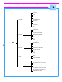
Operator Manual FCM-II
Quick Reference Card Human Interface - Main Menu
16
Operator...
Supervisor...
User
Maintenance/
Service Engineer...
LAS
WVM
Maintenance/
Service Functions
see Card 17
TC
BVM
FCM Base System (see Card 18)
BI (optional)
Shutdown FCM...
Entry...
Schedule...
Order
Production
Module Setup... [F8]
Runout...
Abort...
Start... [F5]
Stop... [F6]
Error Recovery... [F3]
FCM Warnings... [F4]
System Parameters...
SECS-II / GEM (in 5.2)
LAS
Configuration
Available Module (LAS) Number(s)
Exit
Available Module (WVM) Number(s)
WVM
Main
Menu
Enable/Disable
Online/Offline
Remote/Local
TC
BVM
Exit
Options
en
BI (optional)
Associate...
Edit...
ActionSpec
Board Vision Module
Fiducial Alignment
Fiducial Offset Check
Bad Mark Sensing
Exit
Copy from Archive...
Copy to Archive...
Delete...
Format...
Functions... (see Card 19)
MIS
01.02
Summary... [F2]
HOST (in 5.12)
Calibration
Calibration - Functions...
4022 591 94512
Video
Enable/Disable
Online/Offline
Remote/Local
Transport Calibration
Exit
Create Order...
Create System
Calibration File...
Edit...
System Calibration File
Copy from Archive...
Copy to Archive...
Display... [F10]
Delete...
Help for Help
Extended Help
Help
Keys Help
Help Index
About FCM...
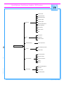
Operator Manual FCM-II
Quick Reference Card Human Interface - Maintenance/Service Functions
17
FCM Base system...
Log to Disk
Copy to Archive...
Enable...
Available Module (LAS) number(s)
Exit
Exchange nozzle...
Manipulate PPU...
Imagecheck...
Home...
Dump...
Reset controller...
Show version...
Show placement count...
SMD-Info
Edit SMD Info
Copy from Archive...
Copy to Archive...
Delete...
Module
Available Module (WVM) number(s)
Exit
Command
Exchange nozzle...
Manipulate PPU...
Home...
Dump...
Reset controller...
Show version...
Show placement count...
Vision
Manipulate Vision
Set display mode
Calibrate camera
SMD-Info
Edit SMD Info
Copy from Archive...
Copy to Archive...
Delete...
Command
Index Beam...
Move Hoist...
Adjust Stoppers...
Home...
Reset controller...
Show version...
Exit
Exercise
Run-in...
Run-out...
SMEMA interface...
System I/O...
Servo
Servo Amplifiers...
Endurance test
Diagnostics
Calibrate
Offset beam...
Maintenance /
Service
Functions
en
WVM
01.02
Options
Logfile
Display
Module
LAS
4022 591 94512
Processes...
Subsystems...
Exit
General
Command
TC
Event Filter
Version...
Date & Time...
Switch to Logger
Switch to OS/2
Exit
Beam...
Hoist...
Parameters & Data...
Status...
Operator Manual FCM-II
Quick Reference Card Human Interface - BVM
18
Move Servo...
Home...
Reset Controller...
Set Display Level...
Command
Show SBIP Status...
Load Board...
Unload Board...
Show Version...
Exit
Teach Fiducial...
Measure Fiducial...
Save Fiducial Teach Data...
Fiducials
Load Fiducial Teach Data...
Copy from Archive...
Copy to Archive...
Delete...
BVM
Teach Badmark...
en
Measure Badmark...
Save Badmark Teach Data...
Badmarks
Load Badmark Teach Data...
Copy from Archive...
Copy to Archive...
01.02
Delete...
Options...
Image
Measure Greylevel...
Calibrate BVM
Copy calibration input from Archive...
4022 591 94512
Copy calibration input to Archive...
Calibrate
Delete calibration input...
Copy calibration output from Archive...
Copy calibration output to Archive...
Delete calibration output...
Operator Manual FCM-II
Quick Reference Card Human Interface - MIS Functions
19
General data
Production times
Production events
Process report
Process graph
Reports
Machine performance
Servo diagnostic
Error history
Show version
Exit
Last report
Print
All reports
Printer control
Troubleshooting
Trace component...
en
Functions...
Start temporary period...
Control
Collect data...
View past period...
01.02
Copy to archive...
Administration
Copy from archive...
Export...
Delete...
4022 591 94512
Machine identification...
Print set...
Parameters
Error causes...
Auto start period...
Operator Manual FCM-II
Philips
Electronic Manufacturing
Technology
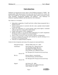
Appendix A: Quick Reference Cards Fast Product Changeover
Contents
These Quick Reference Cards describe the way how to completely change over to a new product in the most effective way.
Card Contents:
-
Pre-start Preparations
Card 2
-
Changeover Sheet
Card 3
-
Changeover Instructions
4022 591 94512
01.02
en
Card 1
Philips
Electronic Manufacturing
Technology
Pre-start Preparations
1
Begin at least 1 hour before Change Over with collecting the following requisites.
ActionSpec. next product
■
System Calibration File next product
■
BVM Calibration File next product
■
Carrier set incl. shims next product
■
Nozzles next product
■
Mounting tools (screwdrivers etc.)
■
Storage box for nozzles
■
Scissors for cutting tape from feeders
■
Storage facility for carrier plates
■
Storage facility for feeder(bar)s
■
Production PCB next product (for width and stopper adjustment of transport system)
■
If required, Maintenance/Service engineer with a service key to adjust the stoppers
4022 591 94512
01.02
en
■
Appendix A: Quick Reference Cards Fast Product Changeover
4022 591 94512
01.02
en
2
1
4
3
Lower MUP
Run-out
product A
(software)
Nozzle
exchange
(software)
A
7
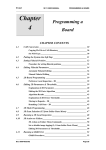
Changeover Sheet
6
5
End nozzle
exchange
(software)
9
8
A
A
A
10
14
13
12
11
15
B
B
16
17
18
Load order
product B
19
20
Start
production
product B
Adjust
stoppers
CLICK!
B
2
Appendix A: Quick Reference Cards Fast Product Changeover
B
4022 591 94512
01.02
en
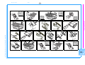
Changeover Instructions
13. Fasten all the “new” carriers.
14. Release all spring clips at the PCB-guides by
releasing the little springs with a screwdriver and
pushing the clips in the direction outwards the
transport.
15. Adjust the width using “new” PCB’s through the
complete X-transport.
16. Set all spring clips at the PCB-guides by pushing
the clips back towards the inside of the transport.
17. Lower all covers and placement modules.
18. Start new Order:
●
Go to the Human Interface
●
Start Order B
●
If required, start the stopper adjust procedure
19. Replace all feeder bars/trolleys, loaded with the
components for the new product, on the FCM-II.
20. Start production of the new product by pressing
twice [F5].
3
Appendix A: Quick Reference Cards Fast Product Changeover
1. Make sure all PCB’s of Order A have left the
machine.
2. Remove all feeder bars/trolleys from left to right.
3. Exchange nozzles:
●
Go to Human Interface and start nozzle
exchange procedure
●
Open Placement Modules
●
Lower MUP
4. Now exchange the nozzles physically and go back
again to the Human Interface in order to end the
nozzle exchange procedure.
5. Open the covers.
6. Set the width of the transport in the widest position.
7. Release all the “old” carriers.
8. Remove and
9. Store the “old” carriers one by one in the storage facility.
10. Clean the whole transport, feeder positions,
dumping bins and eventually the new carriers.
11. Get and
12. Place the “new” carriers one by one on the transport.
Philips
Electronic Manufacturing
Technology