1
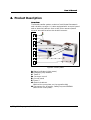
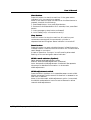
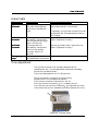
User’s Manual
English
In-Line
Board transfer
system
User´s Manual
This manual is intended for the inline device specified on the previous page. The manual contains information
to assist the operator to start and operate the device properly, and to maintain it. Hardware and software
mentioned in this document are subjected to continuous development and improvement. Consequently, there
may be minor discrepancies between the information in the document and the performance and design of the
hardware and software. Specifications, dimensions and other statements mentioned in this document are
subject to change without prior notice.
Manufacturer and its suppliers shall not be liable for any damages related to the software or hardware, or for any other damages whatsoever caused of
the use of or inability to use any manufacturer product. This is applicable even if manufacturer has been advised of the damage risk. Under any
circumstances, manufacturer’s entire liability shall be limited to replace such defective software or hardware which was originally purchased from
manufacturer.
Printed in Sweden.
ep776_020305u_eng.doc/ 2002-03-28
2
User´s Manual
Contents
1.
S A F E T Y . . . . . . . . . . . . . . . . . . . . . . . . . . . . . . . .. . . . . . . . . . . . . . . . . . . . . . . . . . . . . . . .. . . . . . . . . . . . . . . . . . . . . 4
Emergency stop ........................................................................................................5
Warning signs .......................................................................................................... 6
Warnings ................................................................................................................. 7
Noise........................................................................................................................7
2.
ABOUT THE DOCUMENTAT I O N . . . . . . . . . . . . . . . . . . . . . . . . . . . . . . . . . . . . . . . . . . . . . . . . . . . 8
User's manual........................................................................................................... 8
3.
I N S T A L L A T I O N . . . . . . . . . . . . . . . . . . . . . . . . . . . . . . . . . . . . . . . . . . . . . . . . . . . . . . . . . . . . . . . .. . . . . . . . . . 9
4.
P R O D U C T D E S C R I P T I O N . . . . . . . . . . . . . . . . . . . . . . . . . . . . . . . .. . . . . . . . . . . . . . . . . . . . . . . . . . . 1 1
Controls and indicators.......................................................................................... 12
5.
O P E R A T I O N . . . . . . . . . . . . . . . . . . . . . . . . . . . . . . . .. . . . . . . . . . . . . . . . . . . . . . . . . . . . . . . . . . . . . . . . . . . . . 1 5
Setting up the machine for operation..................................................................... 15
Alarms ................................................................................................................... 15
Alarm table ............................................................................................................ 16
Time adjustment .................................................................................................... 16
6.
MAINTENANCE . . . . . . . . . . . . . . . . . . . . . . . . . . . . . . . . . . . . . . . . . . . . . . . . . . . . . . . . . . . . . . . . . . . . . . . . 1 7
Maintenance schedule ............................................................................................ 17
Cleaning ................................................................................................................ 17
Lubrication ............................................................................................................ 18
Lubricant specification ........................................................................................... 19
7.
SERVICE . . . . . . . . . . . . . . . . . . . . . . . . . . . . . . . . . . . . . . . . . . . . . . . . . . . . . . . . . . . . . . . . . . . . . . . . . . . . . . . . . . 2 0
Exchange of conveyor belt ..................................................................................... 20
Exchange of belt rollers .......................................................................................... 20
Figures
Figure
Figure
Figure
Figure
Figure
Figure
Figure
Figure
Figure
1-1 Electric shock ............................................................................................... 6
1-2 Moving parts................................................................................................ 6
1-3 Attention ..................................................................................................... 7
4-1 Main parts.................................................................................................. 11
4-2 Control panel............................................................................................. 12
5-1 Trimmer setup............................................................................................ 16
6-1 Lubricate the threaded rod ......................................................................... 18
6-2 Lubricate long linear bar............................................................................. 18
7-1 Belt roller ................................................................................................... 20
ep776_020305u_eng.doc/ 2002-03-28
3
User´s Manual
1. Safety
Before starting the machine, it is essential that the operator,
the foreman, and any other personnel involved in the machine
operation understand the following points:
•
The machine must be operated by trained personnel only.
•
Anyone operating this machine must obey all warning
signs. See the section entitled Warning Signs in this
chapter.
•
All personnel involved in machine operation must
understand the use of the emergency stop button and how
to move machine elements in an emergency. See the
following sections entitled Emergency Stop.
•
Do not use chemicals or other substances, which may have
any influence on the operator or other personnel involved
in the machine operation.
•
Apart from weekly, monthly and yearly maintenance as
described in the Maintenance chapter of the User's
Manual, the machine is to be serviced by authorized
personnel only.
•
All covers and shields must be intact, mounted and closed
while the machine is in operation.
•
Do not disable or disengage any built-in safety switches or
sensors.
•
No hands or fingers are allowed near the moving parts of
the machine.
ep776_020305u_eng.doc/ 2002-03-28
4
User´s Manual
Emergency stop
There are two emergency stop buttons. One on top of each
‘tower’.
If an emergency stop button is pushed (activated), all machine
movements are stopped immediately and the pneumatic
cylinder for the shuttle conveyor movement is depressurised.
The emergency stop button has to be pulled up to enable
restart of the machine after an emergency stop.
The machine must always be switched off when hands, fingers,
tools or other objects are in the danger area of movable
machine elements.
Emergency movement of machine elements
If an accident has occurred and an emergency movement of
the shuttle conveyor is required, use the following procedure:
1 . Push (activate) the emergency stop button or press the red
stop button on the control panel.
2 . Push or pull the shuttle conveyor sideways and remove
jammed objects.
Manual movement of the shuttle conveyor should only be
performed in an emergency situation. Manual mechanical
movement can result in machine-part damage.
ep776_020305u_eng.doc/ 2002-03-28
5
User´s Manual
Warning signs
The signs must be kept clean and readable.
If a sign is missing, it must be replaced immediately.
High Voltage
The sign warns of electric shock. Units on which this sign is
placed contain dangerous voltage levels. Power must be
switched off before opening the unit. Only authorized service
personnel are allowed to operate the machine when the unit is
open.
Figure 1-1 Electric shock
This sign is applied as follows.
• One sign on the cover over the electrical cabinet.
Moving parts
The sign warns of moving machine parts. Units on which this
sign is placed contain moving machine parts. Power must be
switched off before maintenance, service or opening the unit.
Only authorized service personnel are allowed to operate the
machine when the unit is open.
Figure 1-2 Moving parts
This sign is applied as follows.
• One sign on each infeed/outfeed cover.
Do NOT try to remove a jammed board while the power is on.
ep776_020305u_eng.doc/ 2002-03-28
6
User´s Manual
Warnings
Throughout the manual this symbol is used to call your
attention when a task is about to be performed, that could be
harmful to personnel or damage the machine. The symbol
often refers to the warning signs, which must be obeyed to
eliminate the risk of injury.
If there are instructions accompanying this symbol, they must
be followed.
Figure 1-3 Attention
Noise
The machine noise is considerably less than 70 dB(A).
ep776_020305u_eng.doc/ 2002-03-28
7
User´s Manual
2. About The Documentation
User's manual
The User's Manual contains information to assist the operator
to start and operate the machine properly.
The Operator's Manual is divided into the following main
parts:
Chapter l:
Safety instructions.
C h a p t e r 2 : Information about the documentation.
C h a p t e r 3 : Installation instructions.
C h a p t e r 4 : Description of the machine and its basic
operation.
C h a p t e r 5 : Operational information for production.
C h a p t e r 6 : Maintenance instructions.
Chapter 7:
ep776_020305u_eng.doc/ 2002-03-28
Service instructions.
8
User´s Manual
3. Installation
Delivery
The machine is delivered fixed on a pallet.
Preparation
Before the installation, prepare the location so, that electric
power and pressurized air is available.
Ambient conditions
The ambient air must be clean.
Allowed humidity:
0 to 35'C
10 to 90 % noncondensing
35 to 60'C
10 to 60 % noncondensing
Allowed temperature:
Operating
5 to 40 'C (41 to 104 'F)
Storage
-40 to 60 'C (-40 to 104 'F)
Technical data
Length
contract.
See specification included in the
Voltage
90-240 VAC
Frequency
50/60 Hz
Power consumption max. 300 W
PCB Length
PCB Width
PCB Thickness
50-450 mm (2 - 17.7”)
50-360 mm (2 - 14.2”)
50-508 mm (2 - 20”)
0.8-4 mm (0.03 – 0.2)
PCB weight
max. 3 kg (6.6 lbs)
The machine can be lifted with one forklift under each ‘tower’.
Put some wooden boards between the forks and the frame
parts before lifting.
ep776_020305u_eng.doc/ 2002-03-28
9
User´s Manual
I ns t a l l a t i o n
The installation must be carried out by authorized service
personnel.
The complete machine line must be carefully levelled along the
shuttle conveyors belts. Use a spirit level across and along the
machines belts when adjusting the feets of the machine.
The fundament must be rigid and sturdy. The machine must
not rock.
The machine must be placed in a manner that allows access to
all parts of the machine and so that service actions are not
obstructed. There must be a free space of one meter around the
machine, except for the other machines included in the
production line.
Mains supply
Must be connected by an authorized electrician.
ep776_020305u_eng.doc/ 2002-03-28
10
User´s Manual
4. Product Description
Overview
The Board transfer system consists of a solid steel framework
and a shuttle conveyor. It is also equipped with a control panel
and an electrical cabinet. One or two photo sensors (board
sensors) are positioned on the shuttle conveyor.
A
B
C
B
D
E
F
G
H
Figure 4-1 Main parts
A . Status indicators (Light tower)
B . Emergency stop buttons
C. Tower 2
D. Conveyor tunnel
E . Control panel
F . Tower 1
G. Electrical cabinet.
(Behind the cover plate, on the opposite side)
H. Connectors for air supply, Safety loop and SMEMA
(Behind the cover plate)
ep776_020305u_eng.doc/ 2002-03-28
11
User´s Manual
Function
The Board transfer system (BTS) transfers boards sideways, a
customer defined distance. When there is a board on an
upstream machine the BTS receives a signal that says board
available. If the shuttle conveyor is empty, it moves to the
infeed position (if not already there). The BTS sends back a
ready signal and the board is transported onto the conveyor.
The shuttle conveyor then moves to the outfeed position and
awaits a ready to receive signal from the downstream machine.
When that signal comes, the board is transported out from the
conveyor and the shuttle conveyor moves back to infeed
position to receive the next board.
Controls and indicators
Control panel
A
B
C
D
E
Figure 4-2 Control panel
A . Stop button
B . Start button
C. Reset button
D. Width mode selector (Option)
E . Widthadjustment switch
ep776_020305u_eng.doc/ 2002-03-28
12
User´s Manual
Start button :
Press this button to start the machine. If the green status
indicator is lit, the machine is started.
Note: If the machine does not start when the Start button is
pressed, check/do the following:
1. Press Reset button, then press Start button.
2. Press and hold Reset button for 5 seconds, then press Start
button.
3. Is any emergency stop button activated?
4. Is the ‘Safety loop’ connected correctly?
Stop button :
Press this button to stop the machine. All machine part
movements are stopped, the pneumatic cylinder is
depressurised and the green status indicator is turned off.
Reset button :
Press this button to reset a shuttle timeout, infeed timeout or
outfeed timeout. Press and hold this button for five seconds to
reset ‘Board on conveyor’.
A reset of ‘Board on conveyor’ is confirmed by alternated
flashing of the red and green status indicator.
Width mode selector (Option) :
Select desired widthadjustment mode.
Manual: Manual widthadjustment is selected.
Auto: Automatic widthadjustment is selected. See separate
document for detailed information on Automatic
widthadjustment.
Widthadjustment switch :
Press the switch up/down to increase/decrease current width.
Width movement continues until the switch is released or an
end limit is reached.
Note: If the Automatic widthadjustment option is mounted,
the Width mode selector has to be set to Manual to allow
manual widthadjustment.
ep776_020305u_eng.doc/ 2002-03-28
13
User´s Manual
Status indicators
These lamps indicate current machine status.
Red lamp:
A cylinder timeout, supply voltage drop, or infeed/outfeed
timeout has occurred. See the alarm table in chapter 5 for
possible causes.
G r e e n l a m p:
p
The machine is running and no error has occurred.
Check the conveyor for obstructive objects before adjusting the
width. If widthadjustment is performed while e.g. a PCB is
located on the conveyor, damage may occur in the width
adjustment mechanism.
ep776_020305u_eng.doc/ 2002-03-28
14
User´s Manual
5. Operation
Setting up the machine for operation
Press Reset button once, and then Start button. Adjust the
width of the conveyor. Width movement continues until the
Widthadjustment switch is released or an end limit is reached.
Make sure the PCB can be moved manually through the whole
length of the conveyor without getting jammed. The machine
is now ready for production.
If the option Automatic widthadjustment is installed, you can
skip the adjustment of width described in the previous section,
and just set the Width mode selector to Auto.
Alarms
An alarm state is always indicated by a lit red signal lamp. See
Controls and indicators, status indicators, in chapter 4 for
more information.
Reset an alarm state by a short press on the Reset button.
Alarms cannot be reset if an Emergency stop button is pressed
down (activated).
Do NOT try to remove a jammed board while the power is on.
ep776_020305u_eng.doc/ 2002-03-28
15
User´s Manual
Alarm table
Alarm type
Description
Recommended action
Cylinder
t i m e o ut
The shuttle conveyor did
not reach expected end
limit within predefined
time.
Remove the obstructive object / make sure
that pressurized air is connected.
Infeed
timeout
Outfeed
timeout
Emergency
stop
If necessary, the cylinder timeout time can
be adjusted. See Time adjustment later in
this chapter.
Remove jammed board / make sure the
width is adjusted correctly.
The board was not
successfully transported
into the shuttle conveyor
within 20 seconds.
The board was not
Remove jammed board / make sure the
successfully transported
width is adjusted correctly.
out from the shuttle
conveyor within 20
seconds.
An Emergency stop button Pull the Emergency stop button up.
is pressed down (activated).
Time adjustment
The cylinder timeout time is always adjusted at the
manufacturer but, if a new adjustment becomes necessary,
follow the procedure below.
The time is adjustable from 5 to 56 seconds.
Disconnect supply voltage by the mains plug.
Locate the PLC in the electrical cabinet.
The trimmer to adjust is identified in fig. 5.1.
Turn the trimmer clockwise ( ) to increase the time.
Turn the trimmer counter-clockwise ( ) to decrease the time.
If the time is set to low, repeated cylinder timeouts will occur.
Figure 5-1 Trimmer setup
ep776_020305u_eng.doc/ 2002-03-28
16
User´s Manual
6. Maintenance
The maintenance of the machine is an important task and
must never be overlooked. Follow the maintenance schedule
and keep the machinery in a clean condition.
Maintenance schedule
Weekly:
• Keep the machine clean, See "Cleaning".
Monthly:
• Check the running surfaces under the conveyor belts for
cleanliness and clean if necessary. See "Cleaning".
• Check the conveyor belt condition and renew the belts if
required.
• Lubricate the four linear bars for telescopic movement. See
“Lubrication”.
Yearly:
•
Lubricate the threaded rods and linear bars for width
adjustment. See “Lubrication”
Cleaning
General:
• Keep the machine clean all over. If necessary, vacuum clean
the area inside the machine as thoroughly as possible.
Photo sensor:
• The photo sensors (board sensors) on the conveyor are
sensitive parts. If they become clogged by dust, the machine
will not work properly. Wipe off dust from the sensors using
a soft cotton rag.
Conveyor:
• Check the running surfaces under the conveyor belts. If they
are dirty and sticky, clean them with a rag and some
washing-up detergent.
ep776_020305u_eng.doc/ 2002-03-28
17
User´s Manual
Lubrication
All bearings are of sealed type and do not require any
additional lubrication.
Threaded rod and linear bar for width adjustment:
• Lubricate the threaded rod and linear bar for width
adjustment. Apply a small amount of lubricant to the entire
length of the rod, and both sides of the bar. Drive the
moving rail to both end positions when lubrication is done.
Figure 6-1 Lubricate the threaded rod
L i n e a r b a r f o r shuttle conveyor movement:
• Lubricate the long linear bar on which the shuttle conveyor
rides. Apply a small amount of lubricant to the entire length
and both sides of the bar.
Figure 6-2 Lubricate long linear bar
ep776_020305u_eng.doc/ 2002-03-28
18
User´s Manual
Lubricant specification
Unless other is stated, use the OKS 270 grease.
Grease should be applied in small amounts, just to give a thin
film.
O K S 270
OKS 270 is the base lubrication grease for the machine.
Data
Full product name: OKS 270
Type: Grease paste
Colour: Whitish
Flash point: >210°C
Supplier in Sweden
TriboTec AB
Box 203
S-435 24 Mölnlycke, Sweden
Phone: Nat. 031-88 78 80 Int. +46 31 78 80
www.tribotec.se
Manufacturer
OKS Spezialschmierstoffe GmbH
Triebstraße 9
D-80993 München
Phone: Nat. 089-14 98 920 Int. +49 89 14 98 920
www.oks-germany.com
ep776_020305u_eng.doc/ 2002-03-28
19
User´s Manual
7. Service
Exchange of conveyor belt
1.
Disconnect the power supply at the mains plug.
2.
Remove the conveyor belt by pulling it to the side.
3.
Fit the new belt by pushing it in place from the side.
Exchange of belt rollers
1.
Disconnect the power supply at the mains plug.
2.
Remove the conveyor belt by pulling it to the side.
3.
Remove the black plastic cover using a 3 mm Allen key.
4.
Remove the aluminium top cover by pulling it gently
straight out.
5.
Unscrew the M6 nut using a 10 mm monkey wrench (BE
adjustable spanner) and replace it with the new belt roller
and the old M6 nut and washer.
Figure 7-1 Belt roller
6.
Replace the conveyor belt.
7.
Replace the aluminium cover and the black plastic cover.
ep776_020305u_eng.doc/ 2002-03-28
20