1
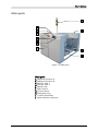
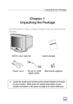
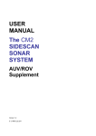
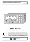
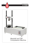
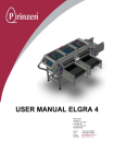
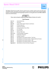
User’s Manual MB809 Dual Unloader User´s Manual This manual is intended for the inline device specified on the previous page. The manual contains information to assist the operator to start and operate the device properly, and to maintain it. Hardware and software mentioned in this document are subjected to continuous development and improvement. Consequently, there may be minor discrepancies between the information in the document and the performance and design of the hardware and software. Specifications, dimensions and other statements mentioned in this document are subject to change without prior notice. Conventions In this manual angle brackets <> are used to indicate certain button names. Example: <Enter> stands for the ENTER button. The manufacturer and its suppliers shall not be liable for any damages related to the software or hardware, or for any other damages whatsoever caused by the use of, or inability to use any manufacturers product. This is applicable even if the manufacturer has been advised of the damage risk. Under any circumstances, the manufacturer’s entire liability shall be limited to replace such defective software or hardware, which was originally purchased from the manufacturer. Printed in Sweden. MB809_090410u.doc II User´s Manual Contents 1. SAFETY ................................................................................................................... 1 Emergency stop buttons ................................................................................................. 2 Emergency movement of machine elements ................................................................. 2 Warning signs ................................................................................................................. 3 Warnings ........................................................................................................................ 4 2. INSTALLATION ...................................................................................................... 5 Site preparation............................................................................................................... 5 Power supply requirements ............................................................................................ 5 Environmental requirements ......................................................................................... 6 Installation...................................................................................................................... 6 3. PRODUCT DESCRIPTION....................................................................................... 7 Main parts....................................................................................................................... 8 General function............................................................................................................. 9 Control panel................................................................................................................ 13 Operation modes .......................................................................................................... 14 Automatic mode ........................................................................................................... 15 Hand mode ................................................................................................................... 17 Option menu ................................................................................................................ 19 Setup mode ................................................................................................................... 20 Conveyor/Shuttle setup................................................................................................ 21 Elevator/Magazine setup............................................................................................... 24 Miscellaneous setup...................................................................................................... 28 Passwords ...................................................................................................................... 29 Alarms ........................................................................................................................... 30 Signal tower .................................................................................................................. 32 4. OPERATION SETUP .............................................................................................. 33 Setting up the machine for operation .......................................................................... 33 5. MAINTENANCE.................................................................................................... 41 Cleaning and lubrication.............................................................................................. 41 Lubricant specifications................................................................................................ 43 Figures Figure 1-1 Electric shock .................................................................................................... 3 Figure 1-2 Moving parts, risk of injury .............................................................................. 3 Figure 1-3 Attention........................................................................................................... 4 Figure 3-1 Main parts ......................................................................................................... 8 Figure 3-2 Control panel.................................................................................................. 13 Figure 3-3 Signal tower .................................................................................................... 32 Figure 5-1 Elevator lead screw and guides ....................................................................... 42 Figure 5-2 Shuttle lead screw and guides ......................................................................... 42 MB809_090410u.doc III User´s Manual 1. Safety Before starting the machine, it is necessary that the operator, foreman, and any other personnel involved in the machine operation, maintenance or service, understand and obey the following: MB809_090410u.doc • Trained personnel must operate the machine only. • Warning signs must be obeyed. • All personnel involved in machine operation must understand the use of the emergency stop buttons and how to move machine elements in case of emergency. See the following sections entitled Emergency Stop Buttons and Emergency Movement of Machine Elements in this chapter. • Apart from weekly maintenance described in Chapter 5, Maintenance, the machine is to be serviced by authorised personnel only. • No hands or fingers are allowed in the vicinity of moving parts. • Ensure that all covers and shields are intact, mounted and closed while the machine is in operation. • Do not disable or disengage any safety switches or sensors. • Do not use chemicals or other substances that may have any influence on the operator or other personnel involved in machine operation. 1 User´s Manual Emergency stop buttons There are two emergency stop buttons on the machine. One on each elevator cabinet. Emergency stop buttons are red and stops all machine movements immediately when pressed down. The button is released by being pulled up and/or turned counter-clockwise. At least one emergency stop button must always be pressed down when hands, fingers, tools or other objects are in the risk area of movable machine elements. Restart To restart the machine after an emergency stop: 1. Release the emergency stop button by pulling it up or turning it counter-clockwise. 2. Start the operation as normal. Emergency movement of machine elements The elevator unit cannot be moved by hand. If an accident has occurred and an emergency movement of the elevator unit is required, use the following procedure: 1. Leave the power on. Do NOT turn off the main power switch. 2. Release the emergency stop button by pulling it up and/or turning it counter-clockwise, and reset the alarm message by pressing <F4> ‘OK’. 3. Press <F3> ‘Hand’> in Main menu to enter Hand mode. 4. Press <F4> in first Hand menu to enter Elevator menu. 5. Use orange buttons ‘’ and ‘’ to move the elevator up and down. After an emergency stop, it is only possible to move the elevator up and down manually by using the two orange arrow buttons. Elevator positioning in any other way requires a home positioning to be performed first. If production is started (Auto mode) after an emergency stop, the elevator will automatically perform a home positioning before performing any other positioning. MB809_090410u.doc 2 User´s Manual Warning signs The warning signs on the machine must be observed as this machine contains moving and electrically live parts. All signs must be kept clean and readable. If a sign is missing, it must be replaced immediately. Electric shock The sign warns of electric shock. Units on which this sign is placed contain dangerous voltage levels. Power must be switched off before opening the unit. Only authorised service personnel are allowed to operate the machine when the unit is open. Figure 1-1 Electric shock Moving parts, risk of injury The sign warns of moving machine parts. If this sign is placed on the machine, there is a risk of injury if any body part is near moving parts. Power must be switched off before service or maintenance. Figure 1-2 Moving parts, risk of injury MB809_090410u.doc 3 User´s Manual Warnings Attention Throughout the manual, this symbol is used to call your attention to commands that starts machine movements or other events that need special attention. The symbol often refers to warning signs, which must be obeyed to eliminate the risk of injury. If there are instructions accompanying this symbol, they must be followed. Figure 1-3 Attention MB809_090410u.doc 4 User´s Manual 2. Installation Before unpacking the machine, make sure that the site is prepared as described below. Then, unpack and position the machine on the site. When the machine is positioned on its site, install it as described last in this chapter. Site preparation Prior to installing the machine, ensure that there are electric power and compressed air available on the site, see requirements below. Make sure environmental conditions meet the requirements specified below. There must be a free space of at least one meter around the machine, except for other devices and machines included in the production line. Power supply requirements Voltage Supply voltage: Voltage tolerance: Frequency: 110-240 VAC ±10% 50/60Hz Compressed air The compressed air must be dry and clean. Pressure: Largest particle size: MB809_090410u.doc 6 bar 5 micron 5 User´s Manual Environmental requirements Temperature Operating: Storage: +5 to +40°C (41 to 104°F) –40 to +60°C (-40 to 140°F) Relative humidity Operating: Storage: <95%, non condensing 100% Dust and dirt The machine does not require a clean-room environment but the level of dust and dirt must be kept as low as possible. The maintenance intervals are shortened by high temperature and dusty or dirty environment. Installation The installation must be carried out by authorised service personnel. Placing the unit Ensure that the floor is sturdy. Place the machine on its site. To be able to install, maintain and service the machine, there must be a free space of at least one meter around it, except for other devices and machines included in the conveyor line. Levelling Level the complete line carefully along the conveyor belts. Use a spirit level across and along the shuttle plate and adjust the feet of the machine. The machine must stay steady on all feet when adjustment is finished. Mains supply Mains supply is to be connected by an authorised electrician. MB809_090410u.doc 6 User´s Manual 3. Product Description This chapter describes the Loader and Unloader. The description is divided into the following main sections: MB809_090410u.doc • Main parts of the machine, page 8. • General function, page 9. • Control panel and buttons in the panel, page 13. • Operation modes, page 14. • Alarms and messages, page 30. • Signal tower and buzzer, page 32. 7 User´s Manual Main parts J E C D F G H I B A Figure 3-1 Main parts Main parts A. Magazine position A B. Magazine position B C. Elevator unit 1 D. Elevator unit 2 E. Shuttle unit F. Main switch G. Control panel H. Emergency stop I. Control electronics J. Status indicator (beacon) MB809_090410u.doc 8 User´s Manual General function The Dual Unloader is designed to unload PCBs from a production line, into one or two PCB magazines. The unloading procedure is different for all six possible work modes. The work mode is easy to change through the operators panel and machine function and unloading procedure for each mode is described below. Letters within brackets in the following descriptions refer to the main parts pointed out on the previous page. Single magazine at position A (Single Mag A) 1. An empty magazine is placed in magazine position A (A). 2. The preceding machine has a board (PCB) available. 3. If the shuttle (E) is ready, i.e, at infeed position and not occupied, the PCB is transported into the shuttle conveyor. 4. The shuttle moves sideways to the programmed position for magazine A. 5. The PCB is transported/pushed into the magazine. 6. If the magazine is not full, the elevator units (C) and (D) moves the magazine to next empty slot. 7. Step 2 to 6 is repeated until the magazine is full. 8. When the magazine is full, the elevator moves to the programmed position for magazine change. Single magazine at position B (Single Mag B) 1. An empty magazine is placed in magazine position B (B). 2. The preceding machine has a board (PCB) available. 3. If the shuttle (E) is ready, i.e, at infeed position and not occupied, the PCB is transported into the shuttle conveyor. 4. The shuttle moves sideways to the programmed position for magazine B. 5. The PCB is transported/pushed into the magazine. 6. If the magazine is not full, the elevator units (C) and (D) moves the magazine to next empty slot. 7. Step 2 to 6 is repeated until the magazine is full. 8. When the magazine is full, the elevator moves to the programmed position for magazine change. MB809_090410u.doc 9 User´s Manual Two magazines, fill A first (Dual Mag, A first) 1. An empty magazine is placed in both magazine position A (A) and magazine position B (B). 2. The preceding machine has a board (PCB) available. 3. If the shuttle (E) is ready, i.e, at infeed position and not occupied, the PCB is transported into the shuttle conveyor. 4. The shuttle moves sideways to the programmed position for magazine A. 5. The PCB is transported/pushed into magazine A. 6. If magazine A is not full, the elevator units (C) and (D) moves the magazine to next empty slot. 7. Step 2 to 6 is repeated until magazine A is full. 8. When magazine A is full, the elevator moves to first empty slot in magazine B. 9. Step 2 to 6 is repeated, for magazine B, until magazine B is full. 10. When magazine B is full (both magazines are full), the elevator moves to the programmed position for magazine change. Two magazines, fill B first (Dual Mag, B first) 1. An empty magazine is placed in both magazine position A (A) and magazine position B (B). 2. The preceding machine has a board (PCB) available. 3. If the shuttle (E) is ready, i.e, at infeed position and not occupied, the PCB is transported into the shuttle conveyor. 4. The shuttle moves sideways to the programmed position for magazine B. 5. The PCB is transported/pushed into magazine B. 6. If magazine B is not full, the elevator units (C) and (D) moves the magazine to next empty slot. 7. Step 2 to 6 is repeated until magazine B is full. 8. When magazine B is full, the elevator moves to first empty slot in magazine A. 9. Step 2 to 6 is repeated, for magazine A, until magazine A is full. 10. When magazine A is full (both magazines are full), the elevator moves to the programmed position for magazine change. MB809_090410u.doc 10 User´s Manual Two magazines, PCBs signaled OK/NG go to magazine A (Dual Mag, OK/NG to A) 1. An empty magazine is placed in both magazine position A (A) and magazine position B (B). 2. The preceding machine has a board (PCB) available. 3. If the shuttle (E) is ready, i.e, at infeed position and not occupied, the PCB is transported into the shuttle conveyor. 4. If sometime during PCB infeed to shuttle, the control system receives an OK/NG signal (Pin 7 and 8 in the SMEMA-connector was shorted), the unloading procedure continues at step 6 below. 5. If the control system does not receive an OK/NG signal during PCB infeed to shuttle, the unloading procedure continues at step 11 below. 6. The shuttle moves sideways to the programmed position for magazine A. 7. The elevator units (C) and (D) moves to the position for next emty slot in magazine A. 8. The PCB is transported/pushed into the magazine. 9. If magazine A becomes full, the elevator moves to the programmed position for magazine change. 10. Unloading procedure continues at step 2 above. 11. The shuttle moves sideways to the programmed position for magazine B. 12. The elevator units (C) and (D) moves to the position for next emty slot in magazine B. 13. The PCB is transported/pushed into the magazine. 14. If magazine B becomes full, the elevator moves to the programmed position for magazine change. 15. Unloading procedure continues at step 2 above. MB809_090410u.doc 11 User´s Manual Two magazines, PCBs signaled OK/NG go to magazine B (Dual Mag, OK/NG to B) 1. An empty magazine is placed in both magazine position A (A) and magazine position B (B). 2. The preceding machine has a board (PCB) available. 3. If the shuttle (E) is ready, i.e, at infeed position and not occupied, the PCB is transported into the shuttle conveyor. 4. If sometime during PCB infeed to shuttle, the control system receives an OK/NG signal (Pin 7 and 8 in the SMEMA-connector was shorted), the unloading procedure continues at step 6 below. 5. If the control system does not receive an OK/NG signal during PCB infeed to shuttle, the unloading procedure continues at step 11 below. 6. The shuttle moves sideways to the programmed position for magazine B. 7. The elevator units (C) and (D) moves to the position for next empty slot in magazine B. 8. The PCB is transported/pushed into the magazine. 9. If magazine B becomes full, the elevator moves to the programmed position for magazine change. 10. Unloading procedure continues at step 2 above. 11. The shuttle moves sideways to the programmed position for magazine A. 12. The elevator units (C) and (D) moves to the position for next empty slot in magazine A. 13. The PCB is transported/pushed into the magazine. 14. If magazine A becomes full, the elevator moves to the programmed position for magazine change. 15. Unloading procedure continues at step 2 above. MB809_090410u.doc 12 User´s Manual Control panel Figure 3-2 Control panel General The machine is controlled from a control panel. The various display views and operation modes are described in the following sections. The control panel shown above, is located on the upper part of elevator unit 1, as shown on page 8. The control panel buttons are described below. Function Buttons <F1>...<F4>: Use these buttons to control the machine. The buttons have different functions depending on mode and display view. A text/symbol describing the function in current display view is shown above each button on the lower text row. Buttons are indicated by bold angle brackets < > and text in this manual. Example: <F1> Auto. Control Buttons < >: Also written as <Enter>, is used to enter password login in setup mode, to select setting options and to enter parameter values. < ← >: Erases the character to the left of the cursor when entering parameter values. MB809_090410u.doc 13 User´s Manual Numerical Buttons <NUM>: Hold this button while entering digits < 0...9 >. Use together with <NUM> to enter values. Finish with <Enter>. <->: Press once for hyphen. Shifts between positive and negative values. < . >: Press twice rapidly for decimal point. Cursor Buttons (orange) < > and < >: Move cursor up or down. These buttons also control manual elevator movements in the elevator control display view. < > and < >: Move cursor to the previous or next option. Operation modes Powering up After completed initiation the Main menu is shown on the control panel. Main menu To control the machine, the following operation modes can be selected from the Main menu. ----[ MAIN MENU ]---Auto Opt Hand Setup • • • • Automatic mode Opt menu (Optional/Misc. Functions)) Hand mode (Manual mode) Setup mode Selecting operation mode You can select the desired operation mode from Main menu as follows: • • • • To enter Automatic mode, press <F1> ‘Auto’. To enter Options menu, press <F2> ‘Opt’. To enter Hand mode, press <F3> ‘Hand’. To enter Setup mode, press <F4> ‘Setup’. Press <F1> ‘«’ repeatedly to return to Main menu from any sub-menu. In case of emergency, use the emergency stop button to stop the movement immediately. MB809_090410u.doc 14 User´s Manual Automatic mode Automatic mode is used for production, i.e. to unload PCBs from a production line into one or two magazines. ----[ MAIN MENU ]---Auto Opt Hand Setup Select Automatic mode by pressing <F1> ‘Auto’ in the Main menu. Line unload cycle description See page 9 to 12 for a description of the unload cycle for all six possible work modes. MB809_090410u.doc 15 User´s Manual Automatic mode display views Parameter/ <Button> Description Automatic mode This display view is shown when entering Automatic mode. AUTO « Message Eject [ 0 ] <F1> « > <F2> > <F3> EJECT <F4> [0] [1] Return to Main menu. Automatic mode is set to OFF. Select next Auto sub menu, see below. Press <F3> to change magazine. Press <F4> to toggle state between [0] and [1]. [0]: Automatic mode is OFF. Production disabled. [1]: Automatic mode is ON. Production enabled. Message Shows different messages during production (Automatic mode ON). One machine states require operator action to continue production. The message below, a short buzzer sound, and a lit yellow lamp indicate the state. Change mag. Description: Depending on work mode, one or both magazines are full and needs to be replaced. Action: Replace the full magazine(s) and start production again. During production, machine status messages (e.g. PCB infeed/outfeed, elevator positioning) are displayed. Stepping:NN Start:NN « Start:FMS <F1> « > <F2> FMS > <F3> <F4> > Stepping: NN Number of magazine slots to move before next PCB is pushed into the magazine. A value of 2 will skip one slot between each PCB. Start: NN Number of the first magazine slot that will be filled. MB809_090410u.doc Note 1: Start slot, stepping, and first magazine slot can only be changed if Automatic mode is OFF and both magazines are empty. Note 2: It is not possible to use different start slot, stepping, and first magazine slot for magazine A and magazine B. <F1> « > Return to previous menu. PCBs: NNA PCBs: NNB Shows number of empty slots in magazine A. Shows number of empty slots in magazine B. PCBs Mag.A: NNA « PCBs Mag.B: NNB Return to previous menu. Toggle first magazine slot. Top = The uppermost magazine slot is slot number 1. Board processing will begin from the top of the magazine and continue downwards. Btm = The lowermost magazine slot is slot number 1. Board processing will begin from the bottom of the magazine and continue upwards. Not used. Select next Auto sub menu, see below. 16 User´s Manual Hand mode Hand mode is used to manually move the elevator, shuttle, pusher, and other controllable machine functions. Select Hand mode by pressing <F3> ‘Hand’ in the Main menu. ----[ MAIN MENU ]---Auto Opt Hand Setup Parameter/ <Button> Description First display view in Hand mode HAND Elevator « » Elevator pos: « Home HAND « NNNmm NNmm/s Shuttle » Shuttle pos: « Home <F1> « > <F2> Not used <F3> > <F4> » > Return to Main menu. Not used in this display. Select next Hand sub menu. Enter current Hand sub menu. NNNmm This value shows the current position of the elevator unit, in millimetres, with reference to the home position sensor that gives a signal to the PLC when the elevator unit is in its uppermost position. NNmm/s This value shows current speed of the elevator. <F1> « > <F2> Home <F3> Not used <F4> Not used Return to previous display. Start an elevator home positioning. Not used in this display. Not used in this display. < > Up < > Down Manually move the elevator upward. Manually move the elevator downward. <F1> « > <F2> > <F3> > <F4> » > Return to Main menu. Select previous Hand sub menu. Select next Hand sub menu. Enter current Hand sub menu. NNNmm This value shows the current position of the shuttle unit, in millimetres, with reference to the home position sensor that gives a signal to the PLC when the shuttle unit is in its position closest to elevator unit 1, where the control panel is located. <F1> « > <F2> Home <F3> Speed sel. <F4> Speed sel. Return to previous display. Start a shuttle home positioning. Toggle Low/High speed. Toggle Low/High speed. < > Up < > Down Manually move the shuttle away from home position. Manually move the shuttle toward home position. NNNmm Speed:Lo MB809_090410u.doc 17 User´s Manual HAND Shuttle conveyor « » Shuttle conveyor « Off/On HAND PCB Pusher « » PCB Pusher « State HAND Light tower « » Light tower « Gre Yel Red HAND Buzzer « » Buzzer « MB809_090410u.doc On/Off Parameter/ <Button> Description <F1> « > <F2> > <F3> > <F4> » > Return to Main menu. Select previous Hand sub menu. Select next Hand sub menu. Enter current Hand sub menu. <F1> « > <F2> Not used <F3> Not used <F4> Off/On > Return to previous display. Not used in this display. Not used in this display. Run PCB conveyor located on the shuttle unit. <F1> « > <F2> > <F3> > <F4> » > Return to Main menu. Select previous Hand sub menu. Select next Hand sub menu. Enter current Hand sub menu. <F1> « > <F2> Not used <F3> Not used <F4> In/Out > Return to previous display. Not used in this display. Not used in this display. Toggle PCB pusher status. <F1> « > <F2> > <F3> > <F4 » > Return to Main menu. Select previous Hand sub menu. Select next Hand sub menu. Enter current Hand sub menu. <F1> « > <F2> Gre > <F3> Yel > <F4> Red > Return to previous display. Toggle green lamp status. Toggle yellow lamp status. Toggle red lamp status. <F1> « > <F2> > <F3> > <F4 » > Return to Main menu. Select previous Hand sub menu. Select next Hand sub menu. Enter current Hand sub menu. <F1> « > <F2> Not used <F3> Not used <F4> On/Off > Return to previous display. Not used in this display. Not used in this display. Toggle buzzer status. 18 User´s Manual Option menu The Option menu contains optional and miscellaneous functions and is easily accessed directly from the Main menu. Select Option menu by pressing <F2> ‘Opt’ in Main menu. ----[ MAIN MENU ]---Auto Opt Hand Setup Parameter/ <Button> Description Option menu This view is displayed when entering Option menu. Options & Misc. « Width Width adjustment « IN OUT Mode <F1> « > <F2> Reserved <F3> Reserved <F4> Width > Return to Main menu. Reserved for customer specific functions. Reserved for customer specific functions. Enter Width adjustment sub menu. <F1> « > <F2> In > <F3> Out > <F4> Mode > Return to previous display. Decrease width. Increase width. Toggle width adjustment mode. Available modes are: 1. Man. (Manual width adjustment) 2. Auto (Automatic width adjustment) Note 1: Auto mode is only selectable if the optional hardware for automatic width adjustment is installed. Note 2: Buttons <F2> In and <F3> Out are disabled if Auto mode is selected. MB809_090410u.doc 19 User´s Manual Setup mode This mode is used to set up the machine for operation. Password login is required to change most settings in Setup mode. Trying to modify a not modifiable parameter or to change a setting without entering correct Password level will generate the message ”Access denied!” for a few seconds on the control panel. Setup sub menus are described on the following pages. Select Setup mode by pressing <F4 Setup> in the Main menu. ----[ MAIN MENU ]---Auto Rcp Hand Setup Parameter/ <Button> Description Setup main menu This view is displayed when entering Setup mode from Main menu. ----[ SETUP MENU ]---Conv Elev Other <F1> « > Return to Main menu. <F2> Conv > Select Setup sub menu that contains all conveyor/shuttle related settings. <F3> Elev > Select Setup sub menu that contains all elevator/magazine related settings. <F4> Other > Select Setup sub menu that contains settings not covered by the two sub menus above. « The three Setup sub menus above and their respective sub menus are described on the following pages. MB809_090410u.doc 20 User´s Manual Conveyor/Shuttle setup Settings and parameters related to the shuttle conveyor and shuttle are described on the following pages. Select conveyor/shuttle setup by pressing <F2 Conv> in the Setup main menu. ----[ SETUP MENU ]---Conv Elev Other « Setup Infeed pos. « » InfeedPos: NNNmm « ↑↓ Set GO Setup Outfeed A pos. « » Out A Pos: NNNmm « ↑↓ Set GO MB809_090410u.doc Parameter/ <Button> Description <F1> « > <F2> > <F3> > <F4> » > Return to Main menu. Return to Setup main menu. Select next Setup sub menu. Enter selected Setup sub menu. <F1> « > <F2> ↑↓ > Return to previous display. Go to shuttle control. <F3 Set > Sets the current shuttle conveyor position as the position where PCBs will be transported into the shuttle conveyor from the preceding machine. <F4 GO > Move the shuttle to the position entered at NNNmm. NNNmm Distance in millimetres, from home position to PCB infeed position. This value can be changed manually via the control panel. Do not press <F3 Set > after a manual change. <F1> « > <F2> > <F3> > <F4> » > Return to Main menu. Select previous Setup sub menu. Select next Setup sub menu. Enter selected Setup sub menu. <F1> « > <F2> ↑↓ > Return to previous display. Go to shuttle control. <F3 Set > Sets the current shuttle conveyor position as the position where PCBs will be transported/pushed from the shuttle conveyor into magazine A. <F4 GO > Move the shuttle to the position entered at NNNmm. NNNmm Distance in millimetres, from home position to the position where PCBs are transported/pushed into magazine A. This value can be changed manually via the control panel. Do not press <F3 Set > after a manual change. 21 User´s Manual Setup Outfeed B pos. « » Out B Pos: NNNmm « ↑↓ Set GO Setup Home interval « » Home interval: NN « Setup Max. limit « » Max. limit: « ↑↓ NNNmm Set GO MB809_090410u.doc Parameter/ <Button> Description <F1> « > <F2> > <F3> > <F4> » > Return to Main menu. Select previous Setup sub menu. Select next Setup sub menu. Enter selected Setup sub menu. <F1> « > <F2> ↑↓ > Return to previous display. Go to shuttle control. <F3 Set > Sets the current shuttle conveyor position as the position where PCBs will be transported/pushed from the shuttle conveyor into magazine B. <F4 GO > Move the shuttle to the position entered at NNNmm. NNNmm Distance in millimetres, from home position to the position where PCBs are transported/pushed into magazine B. This value can be changed manually via the control panel. Do not press <F3 Set > after a manual change. <F1> « > <F2> > <F3> > <F4> » > Return to Main menu. Select previous Setup sub menu. Select next Setup sub menu. Enter selected Setup sub menu. <F1> « > <F2> Not used <F3> Not used <F4> Not used Return to previous display. NN Number of processed PCBs between home positionings. A value of 0 (zerow) disables home positionings during production. <F1> « > <F2> > <F3> > <F4> » > Return to Main menu. Select previous Setup sub menu. Select next Setup sub menu. Enter selected Setup sub menu. <F1> « > <F2> ↑↓ > Return to previous display. Go to shuttle control. <F3 Set > Sets the current shuttle conveyor position as the physical longest possible distance from the home position sensor. <F4 GO > Move the shuttle to the position entered at NNNmm. NNNmm Distance in millimetres, from home position to the outermost allowed position for the shuttle conveyor. This value can be changed manually via the control panel. Do not press <F3 Set > after a manual change. 22 User´s Manual Setup PCB wait time « » PCB Max. wait time « NNN seconds Setup Infeed timeout « » PCB Infeed timeout: « NN seconds MB809_090410u.doc Parameter/ <Button> Description <F1> « > <F2> > <F3> > <F4> » > Return to Main menu. Select previous Setup sub menu. Select next Setup sub menu. Enter selected Setup sub menu. <F1> « > <F2> Not used <F3> Not used <F4> Not used Return to previous display. NNN Maximum allowed time for a PCB to remain on the shuttle conveyor before the buzzer sounds and an info message is displayed. A value of 0 (zero) deactivates the function. <F1> « > <F2> > <F3> > <F4> » > Return to Main menu. Select previous Setup sub menu. Select next Setup sub menu. Enter selected Setup sub menu. <F1> « > <F2> Not used <F3> Not used <F4> Not used Return to previous display. NN Maximum allowed completion time for a PCB infeed to shuttle conveyor from the preceding machine. 23 User´s Manual Elevator/Magazine setup Settings and parameters related to the elevator and magazines are described on the following pages. Select elevator/magazine setup by pressing <F3 Elev> in the Setup main menu. ----[ SETUP MENU ]---Conv Elev Other « Setup Upper slot « » Upper slot: NNNmm « ↑↓ Set GO Setup Lower slot « » Lower slot: NNNmm « ↑↓ Set GO MB809_090410u.doc Parameter/ <Button> Description <F1> « > <F2> > <F3> > <F4> » > Return to Main menu. Return to Setup main menu. Select next Setup sub menu. Enter selected Setup sub menu. <F1> « > <F2> ↑↓ > Return to previous display. Go to elevator control. <F3 Set > Sets the current elevator unit position as the level of the uppermost slot in the magazine. <F4 GO > Move the elevator to the position entered at NNNmm. NNNmm Distance in millimetres, from home position to first slot. This value can be changed manually via the control panel. Do not press <F3 Set > after a manual change. <F1> « > <F2> > <F3> > <F4> » > Return to Main menu. Select previous Setup sub menu. Select next Setup sub menu. Enter current Setup sub menu. <F1> « > <F2> ↑↓ > Return to previous display. Go to elevator control. <F3 Set > Sets the current elevator unit position as the level of the lowermost slot in the magazine. <F4 GO > Move the elevator to the position entered at NNNmm. NNNmm Distance in millimetres, from home position to last slot. 24 User´s Manual Setup Mag.Change lvl « » MagChangeLvl:NNNmm « ↑↓ Set GO Setup Slot amount « » Slot amount: NN « Setup Home interval « » Home interval: NN « MB809_090410u.doc Parameter/ <Button> Description <F1> « > <F2> > <F3> > <F4> » > Return to Main menu. Select previous Setup sub menu. Select next Setup sub menu. Enter current Setup sub menu. <F1> « > <F2> ↑↓ > Return to previous display. Go to elevator control. <F3 Set > Sets the current elevator unit position as the level where magazine changes will take place. <F4 GO > Move the elevator to the position entered at NNNmm. NNNmm Distance in millimetres, from home position to magazine change level. <F1> « > <F2> > <F3> > <F4> » > Return to Main menu. Select previous Setup sub menu. Select next Setup sub menu. Enter selected Setup sub menu. <F1> « > <F2> Not used <F3> Not used <F4> Not used Return to previous display. NN Total number of slots in the magazine. <F1> « > <F2> > <F3> > <F4> » > Return to Main menu. Select previous Setup sub menu. Select next Setup sub menu. Enter selected Setup sub menu. <F1> « > <F2> Not used <F3> Not used <F4> Not used Return to previous display. NN Number of processed magazines (Magazine A + B) between elevator home positionings. A value of 0 (zerow) disables elevator home positionings during production (recommended). 25 User´s Manual Setup PCBs/mag.slot « » Number of PCBs in « the same slot: N Parameter/ <Button> Description <F1> « > <F2> > <F3> > <F4> » > Return to Main menu. Select previous Setup sub menu. Select next Setup sub menu. Enter selected Setup sub menu. <F1> « > <F2> Not used <F3> Not used <F4> Not used Return to previous display. N Number of PCBs that are pushed in to the same magazine slot. Use this function with caution. A value higher than 1 may cause damage to PCBs. Setup Max. limit « » Max. limit: « ↑↓ Setup Mag Near Full lvl « NNNmm Set GO » Mag.A: NA Mag.B: NB « MB809_090410u.doc <F1> « > <F2> > <F3> > <F4> » > Return to Main menu. Select previous Setup sub menu. Select next Setup sub menu. Enter selected Setup sub menu. <F1> « > <F2> ↑↓ > Return to previous display. Go to elevator control. <F3> Set > Sets the current elevator unit position as the lowermost allowed elevator position. <F4> GO > Move the elevator to the position entered at NNNmm. NNNmm Distance in millimetres, from home position to max. limit. <F1> « > <F2> > <F3> > <F4> » > Return to Main menu. Select previous Setup sub menu. Select next Setup sub menu. Enter selected Setup sub menu. <F1> « > <F2> Not used <F3> Not used <F4> Not used Return to previous display. NA Magazine A near full level. A short sound on the buzzer is generated when the number of empty slots in magazine A equals NA and the yellow beacon lamp will be lit if NA equals or is greater than the actual number of empty slots in magazine A. A value of 0 (zero) disables this function for magazine A. NB Magazine B near full level. A short sound on the buzzer is generated when the number of empty slots in magazine B equals NB and the yellow beacon lamp will be lit if NB equals or is greater than the actual number of empty slots in magazine B. A value of 0 (zero) disables this function for magazine B. 26 User´s Manual Setup Sync elevators « » Parameter/ <Button> Description <F1> « > <F2> > <F3> > <F4> » > Return to Main menu. Select previous Setup sub menu. Select next Setup sub menu. Enter selected Setup sub menu. This function makes it possible to run elevator unit 1 and elevator unit 2 separately and should only be used if the two elevator units are misaligned. It is possible to get the two elevator units misaligned if service (elevator drive belt replacement or motor replacement) is done on an elevator unit. In rare cases the two elevator units can also be misaligned if an emergency stop button is pressed when the elevator is moving. A:NNA B:NNB Aoff Boff « <F1> « > Return to previous display. <F2> Aoff/on > Enables/disables movement for servo motor A (elevator unit 1). <F3> Not used <F4> Boff/on > Enables/disables movement for servo motor B (elevator unit 2). < > Up < > Down (orange buttons) Manually move elevator unit 1 or/and 2 upward. Manually move elevator unit 1 or/and 2 downward. NNA Shows total distance moved for elevator unit 1. NNB Shows total distance moved for elevator unit 2. Note: NNA and NNB only shows the distance moved in current sync session. Both NNA and NNB is reset each time this display view is entered. Elevator unit 1 and 2 are always synced before the machine is shipped to customer site. The sync function should be used with extreme caution as it can damage machine parts if incorrectly used. An elevator sync procedure should only be performed if shuttle conveyor PCB level differs between magazine position A and magazine position B. MB809_090410u.doc 27 User´s Manual Miscellaneous setup Miscellaneous settings and parameters are described on the following pages. Select miscellaneous setup by pressing <F4 Other> in the Setup main menu. ----[ SETUP MENU ]---Conv Elev Other « Setup Work mode « » Work mode « Setup Info buzz time « ↑ ↓ » Info buzzer ON time: « NN seconds Setup Def. settings « » Setup Def. settings « MB809_090410u.doc [SET] Parameter/ <Button> Description <F1> « > <F2> > <F3> > <F4> » > Return to Main menu. Return to Setup main menu. Select next Setup sub menu. Enter selected Setup sub menu. <F1> « > <F2> Not used <F3> ↑ > Return to previous display. <F4> ↓ > Scroll work mode list downward. Work mode Available work modes are (see page 9 to 12): 1. Single Mag A 4. Dual Mag, B first 2. Single Mag B 5. Dual Mag, OK/NG to A 3. Dual Mag, A first 6. Dual Mag, OK/NG to B <F1> « > <F2> > <F3> > <F4> » > Return to Main menu. Select previous Setup sub menu. Select next Setup sub menu. Enter selected Setup sub menu. <F1> « > <F2> Not used <F3> Not used <F4> Not used Return to previous display. NN Time, in seconds, for how long the buzzer should sound when an info message is displayed on the operator’s panel during production. A value of 0 (zero) deactivates the function. <F1> « > <F2> > <F3> Not used <F4> » > Return to Main menu. Select previous Setup sub menu. <F1> « > <F2> Not used <F2> Not used Return to previous display. <F4> SET > Sets all changeable parameters and settings to factory default settings. Scroll work mode list upward. Enter selected Setup sub menu. Reset all settings to factory default settings. 28 User´s Manual Passwords A password is required to change/view some of the settings under the Setup sub menu. A password is not required to operate the machine during production. Password levels Settings that require a password are assigned different password levels, depending on how critical the setting is. Available password levels are: • Password 1. User level 1. The password is ”1” by default. • Password 2. User level 2. The password is ”2” by default. • Password 3. Service level. The password is ”3” by default. • Password 4. Manufacturer level 1. • Password 5. Manufacturer level 2. • Password 6. Not used. • Password 7. Not used. • Password 8. Not used. Parameter/ <Button> Description Password login view. Password: *** MB809_090410u.doc <NUM> + <0...9> Use the numerical buttons to enter password for desired security level and close with <Enter>. <F1 > < > Return to Setup main view. Close password login. The action taken depends on the following: - If no password is entered, this view is left without any action. - If wrong password is entered, it is deleted and a new password can be entered, or the view can be left by pressing <Enter> again. - If correct password for any security level is entered, the message ”Level is...” will be displayed for a few seconds, showing the corresponding security level before the previous display view is shown again. 29 User´s Manual Alarms Alarms An alarm that occurs in any mode is indicated with a buzzer sound, red warning light, and an alarm text on the control panel. The alarm text remains on the control panel display until the alarm is reset by pressing <F4 OK> or <Enter>, or the power is turned off. Alarm table The table below contains the alarms and messages that can be shown on the control panel. ALARM MESSAGE <OK> Alarm message / <Button> <F4 OK > Description < > Press <Enter> for reset and return to Main menu. ALARM MESSAGE See alternatives below. Access denied! Cause: Action: Press <F4 OK > for reset and return to previous display. Trying to modify a not modifiable parameter or to change a setting without entering correct Password level will generate this message for a few seconds on the control panel. Enter a valid password before changing parameters. PLC stopped! Cause: Action: Shuttle not home positioned! Cause: Action: Elevator not home positioned! Cause: Action: The PLC is in programming mode. Flip the Stop/Run-switch on the PLC to Run position. A shuttle movement was requested and the shuttle is not home positioned. Perform a home positioning or start production (Auto mode). An elevator movement was requested and the elevator is not home positioned. Perform a home positioning or start production (Auto mode). Elevator servo alarm! Cause: A servo alarm occurred for some reason. Action: Pusher not home! Cause: Action: MB809_090410u.doc Press F3 <Reset> on the error screen and then F4 <OK>. Turn the main switch off and check that all cables going to the servo modules are firmly attached. Turn the main switch on. An elevator or shuttle movement was requested and the pusher is not fully retracted. Check air pressure, check pusher home position sensor. 30 User´s Manual Alarm message / <Button> Emergency stop! Cause: Action: Shuttle jammed! Cause: Action: Pusher timeout! Cause: Action: PCB infeed timeout! Cause: Action: Shuttle reached max. limit! Cause: Action: Automatic width adj. error! Cause: Action: Shuttle direction error! Cause: Action: PCB conveyor jam sensor blocked! Cause: Action: PCB waiting on conveyor! Cause: Action: Description One or more emergency stop button(s) is pressed down. Pull up the emergency stop button(s). Restart the machine. A shuttle movement was expected but no position encoder signals were received within predefined time. Remove jammed object, change motor relays, check motor voltage, or replace the shuttle motor. The pusher did not reach expected end position (in or out) within predefined time. Check air pressure, check pusher end position sensors. The shuttle conveyor did not receive a PCB within expected time. Remove partially transferred PCB and/or increase infeed timeout time. See page 23. The shuttle has reached the maximum allowed (software) distance away from the home position sensor. Go to shuttle (conv) menu and perform a home positioning. Automatic width adjustment is not working properly. Remove jammed object and restart the machine. A shuttle movement was performed and the encoder signals received by the PLC are inverted. Change motor relays, check motor voltage, or replace the shuttle motor. The shuttle conveyor jam sensor was activated when an elevator or shuttle movement was requested. Remove object activating the sensor. A PCB has been waiting for a time (adjustable) on the shuttle conveyor. Change magazine. Magazine missing! Cause: Action: MB809_090410u.doc A magazine is missing at current shuttle position. Put an empty magazine on the elevator / check magazine present sensors. 31 User´s Manual Signal tower The machine is equipped with a signal tower that is positioned on top of the elevator unit. The signal specification for the signal tower cannot be changed. It can, however, be customised if the signal specification is available before manufacturing. Figure 3-3 Signal tower Buzzer A built-in buzzer is on when an alarm is active. Reset alarms by pressing <F4 OK> or <Enter>. The buzzer also sounds shortly to call the operators attention when some events occur. Red light Red light indicates active alarm. The red light may also be lit shortly during start-up and shutdown. Yellow light Yellow light indicates a state that requires operator action. With Automatic mode ON, an Info message is shown on the control panel simultaneously with this light. Green light Green light indicates running machine, i.e. the machine is in production in Automatic mode. MB809_090410u.doc 32 User´s Manual 4. Operation Setup Setting up the machine for operation The setup procedures in this chapter are intended to be performed in a continuous sequence. Therefore, the activity numbering is made consecutively throughout the chapter. Starting Up 1. Switch on the machine with the main power switch and wait until Main menu is displayed. ----[ MAIN MENU ]---Auto Opt Hand Setup 2. Press <F2 ‘Hand’> and <F4 »> to enter elevator control. Elevator pos: « Home 123mm 0mm/s 3. Press <F2 ‘Home’> to start a home positioning of the elevator unit. The elevator unit will then search for the home position sensor located near its physical uppermost position. 4. When home positioning is done, Press <F1 «> once, <F3 > once, and <F4 »> to enter shuttle control. Shuttle pos: « Home NNNmm Speed:Lo 5. Press <F2 ‘Home’> to start a home positioning of the shuttle unit. The shuttle unit will then search for the home position sensor located near elevator unit 1. 6. When home positioning is done, Press <F1 «> twice to return to Main menu. 7. Press <F4 ‘Setup’> to go to Setup main menu. ----[ SETUP MENU ]---Conv Elev Other « MB809_090410u.doc 33 User´s Manual 8. Put a magazine in both magazine positions. Adjusting shuttle infeed position Shuttle infeed position is the position of the shuttle where PCBs from a preceding machine is transported into the shuttle conveyor. 9. Press <F2 ‘Conv’> in Setup main menu to go to shuttle/conveyor setup. 10. Press <F4 »> to go to “Setup Infeed pos.’. InfeedPos: « ↑↓ 089mm Set GO 11. Press <F2> ↑↓> to go to shuttle control, use the orange buttons < > and < > to move the shuttle to a position where PCB transfers from a preceding machine into the shuttle conveyor is possible. Press <F1 «> to return to Infeed pos sub menu, press <F3> Set> to store current shuttle position as the position where PCBs are transferred from a preceding machine into the shuttle conveyor. Fine adjustments are possible by manually modifying the numerical value and pressing <F4> GO> to verify position. Instructions on how to use the numerical buttons are found on page 14. Do not press <F3> Set> after manually modifying the numerical value. InfeedPos: « ↑↓ 089mm Set GO 12. Press <F1 «> to go back to the previous screen. MB809_090410u.doc 34 User´s Manual Adjusting shuttle outfeed position A (magazine A) Shuttle outfeed position A is the position of the shuttle where PCBs are transported/pushed into magazine A. 13. Press <F3 > once and <F4 »> to go to “Setup Outfeed A pos.’. Out A Pos: « ↑↓ 123mm Set GO 14. Press <F2> ↑↓> to go to shuttle control, use the orange buttons < > and < > to move the shuttle to a position where PCB transfers to magazine A is possible. Press <F1 «> to return to Out A pos sub menu, press <F3> Set> to store current shuttle position as the position where PCBs are transferred to magazine A. Fine adjustments are possible by manually modifying the numerical value and pressing <F4> GO> to verify position. Instructions on how to use the numerical buttons are found on page 14. Do not press <F3> Set> after manually modifying the numerical value. Out A Pos: « ↑↓ 123mm Set GO 15. Press <F1 «> to go back to the previous screen. Adjusting shuttle outfeed position B (magazine B) Shuttle outfeed position B is the position of the shuttle where PCBs are transported/pushed into magazine B. 16. Press <F3 > once and <F4 »> to go to “Setup Outfeed B pos.’. Out B Pos: « MB809_090410u.doc ↑↓ 345mm Set GO 35 User´s Manual 17. Press <F2> ↑↓> to go to shuttle control, use the orange buttons < > and < > to move the shuttle to a position where PCB transfers to magazine B is possible. Press <F1 «> to return to Out B pos sub menu, press <F3> Set> to store current shuttle position as the position where PCBs are transferred to magazine B. Fine adjustments are possible by manually modifying the numerical value and pressing <F4> GO> to verify position. Instructions on how to use the numerical buttons are found on page 14. Do not press <F3> Set> after manually modifying the numerical value. Out B Pos: « ↑↓ 345mm Set GO 18. Press <F1 «> twice to return to Setup main menu. Setting upper slot level Upper slot level is the level of the elevator where PCBs from the shuttle conveyor can be transferred/pushed into the uppermost slot in the magazines. 19. Press <F3 ‘Elev’> in Setup main menu to go to elevator/magazine setup. 20. Press <F4 »> to go to ‘Setup Upper slot’. Upper slot: « MB809_090410u.doc ↑↓ 693mm Set GO 36 User´s Manual 21. Press <F2> ↑↓> to go to elevator control, use the orange buttons < > and < > to move the elevator to desired level, press <F1 «> to return to Upper slot sub menu, press <F3> Set> to store current elevator position as the uppermost available magazine slot. Fine adjustments are possible by manually modifying the numerical value and pressing <F4> GO> to verify position. Instructions on how to use the numerical buttons are found on page 14. Do not press <F3> Set> after manually modifying the numerical value. Upper slot: « ↑↓ 693mm Set GO 22. Press <F1 «> to go back to the previous screen. Setting lower slot level Lower slot level is the level of the elevator where PCBs from the shuttle conveyor can be transferred/pushed into the lowermost slot in the magazines. 23. Press <F3 > once and <F4 »> to go to ’Setup Lower slot’. Lower slot: « ↑↓ 213mm Set GO 24. Press <F2> ↑↓> to go to elevator control, use the orange buttons < > and < > to move the elevator to desired level, press <F1 «> to return to Lower slot sub menu, press <F3> Set> to store current elevator position as the lowermost available magazine slot. Fine adjustments are possible by manually modifying the numerical value and pressing <F4> GO> to verify position. Instructions on how to use the numerical buttons are found on page 14. Do not press <F3> Set> after manually modifying the numerical value. Lower slot: « ↑↓ 213mm Set GO 25. Press <F1 «> to go back to the previous screen. MB809_090410u.doc 37 User´s Manual Setting magazine change level Magazine change level is the elevator level where magazine changes are performed. 26. Press <F3 > once and <F4 »> to go to ’Setup Mag. change level’. MagChangeLvl:512mm « ↑↓ Set GO 27. Press <F2> ↑↓> to go to elevator control, use the orange buttons < > and < > to move the elevator to desired level, press <F1 «> to return to Mag. change level sub menu, press <F3> Set> to store current elevator position as the level where magazine changes will be performed. Fine adjustments are possible by manually modifying the numerical value and pressing <F4> GO> to verify position. Instructions on how to use the numerical buttons are found on page 14. Do not press <F3> Set> after manually modifying the numerical value. MagChangeLvl:512mm « ↑↓ Set GO 28. Press <F1 «> to go back to the previous screen. Setting slot amount Slot amount is the total number of slots in the magazine. 29. Press <F3 > once and <F4 »> to go to ’Setup Slot amount’. Slot amount: 50 « 30. Use the numerical buttons and enter the total number of slots. Instructions on how to use the numerical buttons are found on page 14. 31. Press <F1 «> twice to return to Setup main menu. MB809_090410u.doc 38 User´s Manual Setting work mode Work mode determines how the machine distributes PCBs when in production. See page 9-12 for descriptions of the different work modes. 32. Press <F4 ‘Other’> in Setup main menu to go to miscellaneous settings. 33. Press <F4 »> to go to ’Setup Work mode’. Work mode « ↑ ↓ 34. Cycle through available work modes by using buttons <F3 ↑> and <F4 ↓>. Selected work mode is the one shown when leaving current display. 35. Press <F1 «> three times to return to Main menu. Adjusting width 36. Press <F2 ‘Opt’> to go to optional/width settings. Options & Misc. « Width 37. Press <F4 ‘Width’> to enter Width adjustment menu. Width adjustment « IN OUT Man. 38. Press <F2> or <F3> to adjust width of the PCB conveyor, or press <F4> to change width adjustment to auto if automatic width adjustment (optional function) is used in the production line. Width adjustment « IN OUT Man. 39. Press <F1 «> repeatedly to go back to Main menu. MB809_090410u.doc 39 User´s Manual Finishing the Setup The operation setup is now completed. Set the machine in production mode as described in the section Automatic mode, in Chapter 3, page 15. Other settings See page 20 and forward for information on (optional) functions and settings that are not covered by the above operation setup. The machine contains moving parts that can cause damage and personal injury, if handled incorrectly. Read the safety instructions in Chapter 1, Safety. MB809_090410u.doc 40 User´s Manual 5. Maintenance Cleaning and lubrication The maintenance instructions in this chapter comprise weekly, monthly and six month maintenance for the machine. The maintenance is very important for a continuous operation without unintentional stops. Follow the maintenance instructions carefully and keep the machine clean. Lubricants Unless other is stated, use the OKS 270 grease. Grease should be applied in small amounts, just to give a thin film. Specifications and part #’s for the lubricants are found in the end of this chapter. MB809_090410u.doc 41 User´s Manual Weekly Clean the machine. Clean the machine all over. Wipe off dust and dirt from all optical sensors. Monthly Lubricate elevator and shuttle lead screw. Apply grease to the whole length of the two lead screws. Six month Lubricate all elevator and shuttle guides. Lubricate elevator guides, shuttle guides, width adjustment guide, and pusher guide. Apply a small amount of grease to the whole length of all guides. Lead screw Elevator guide Elevator guide Figure 5-1 Elevator lead screw and guides Pusher guide Width adj. guide Lead screw Shuttle guide Shuttle guide Figure 5-2 Shuttle lead screw and guides MB809_090410u.doc 42 User´s Manual Lubricant specifications This section contains lubricant data for: • OKS 270 grease OKS 270 OKS 270 is the base lubrication grease for the machine. Data Full product name: OKS 270 Type: Grease paste Colour: Whitish Flash point: >210°C Supplier in Sweden TriboTec AB Box 203 S-435 24 Mölnlycke, Sweden Phone: Nat. 031-88 78 80 Int. +46 31 78 80 www.tribotec.se Manufacturer OKS Spezialschmierstoffe GmbH Triebstraße 9 D-80993 München Phone: Nat. 089-14 98 920 Int. +49 89 14 98 920 www.oks-germany.com MB809_090410u.doc 43