1
Errata
Title & Document Type: 8647A Signal Generator Operation and Service Guide
Manual Part Number: 08647-90006
Revision Date: March 1984
HP References in this Manual
This manual may contain references to HP or Hewlett-Packard. Please note that HewlettPackard's former test and measurement, semiconductor products and chemical analysis
businesses are now part of Agilent Technologies. We have made no changes to this
manual copy. The HP XXXX referred to in this document is now the Agilent XXXX.
For example, model number HP8648A is now model number Agilent 8648A.
About this Manual
We’ve added this manual to the Agilent website in an effort to help you support your
product. This manual provides the best information we could find. It may be incomplete
or contain dated information, and the scan quality may not be ideal. If we find a better
copy in the future, we will add it to the Agilent website.
Support for Your Product
Agilent no longer sells or supports this product. You will find any other available
product information on the Agilent Test & Measurement website:
www.tm.agilent.com
Search for the model number of this product, and the resulting product page will guide
you to any available information. Our service centers may be able to perform calibration
if no repair parts are needed, but no other support from Agilent is available.
Operation and Service
Guide
HP 8647A Signal Generator
SERIAL NUMBERS
This manual applies directly to all instruments with serial prefix
3247A and 3349A.
HP Wt NO. 08647-90006
Printed in USA March 1994
Notice. The information contained in this document is subject to
change without notice.
Hewlett-Packard makes no warranty of any kind with regard to this
material, including but not limited to, the implied warranties of
merchantability and fitness for a particular purpose. Hewlett-Packard
shall not be liable for errors contained herein or for incidental
or consequential damages in connection with the furnishing,
performance, or use of this material.
@ Copyright Hewlett-Packard Company 1994
All Rights Reserved. Reproduction, adaptation, or translation without
prior written permission is prohibited, except as allowed under the
copyright laws.
1400 Fountaingrove Parkway, Santa Rosa CA, 95403-1799, USA
Reproduced with Permission, Courtesy of Agilent Technologies, Inc.
Certification
Regulatory
Information
Warranty
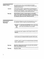
Hewlett-Packard Company certifies that this product met its
published specifications at the time of shipment from the factory.
Hewlett-Packard further certifies that its calibration measurements
are traceable to the United States National Institute of Standards and
Technology, to the extent allowed by the Institute’s calibration facility,
and to the calibration facilities of other International Standards
Organization members.
The regulatory information is in Chapter 4, “Specifications.
This Hewlett-Packard instrument product is warranted against defects
in material and workmanship for a period of one year from date of
shipment. During the warranty period, Hewlett-Packard Company
will, at its option, either repair or replace products which prove to be
defective.
For warranty service or repair, this product must be returned to a
service facility designated by Hewlett-Packard. Buyer shall prepay
shipping charges to Hewlett-Packard and Hewlett-Packard shall pay
shipping charges to return the product to Buyer. However, Buyer shall
pay all shipping charges, duties, and taxes for products returned to
Hewlett-Packard from another country.
Hewlett-Packard warrants that its software and firmware designated
by Hewlett-Packard for use with an instrument will execute
its programming instructions when properly installed on that
instrument. Hewlett-Packard does not warrant that the operation
of the instrument, or software, or firmware will be uninterrupted or
error-free.
LIMITATION
OF
WARRANTY
The foregoing warranty shall not apply to defects resulting from
improper or inadequate maintenance by Buyer, Buyer-supplied
software or interfacing, unauthorized modification or misuse,
operation outside of the environmental specifications for the
product, or improper site preparation or maintenance.
NO OTHER WARRANTY IS EXPRESSED OR IMPLIED.
HEWLETT-PACKARD SPECIFICALLY DISCLAIMS THE IMPLIED
WARRANTIES OF MERCHANTABILITY AND FITNESS FOR A
PARTICULAR PURPOSE.
EXCLUSIVE
REMEDIES
THE REMEDIES PROVIDED HEREIN ARE BUYER’S SOLE AND
EXCLUSIVE REMEDIES. HEWLETT-PACKARD SHALL NOT BE
LIABLE FOR ANY DIRECT, INDIRECT, SPECIAL, INCIDENTAL, OR
CONSEQUENTIAL DAMAGES, WHETHER J3ASED ON CONTRACT,
TORT, OR ANY OTHER LEGAL THEORY.
iii
Assistance
iv
Product maintenance agreements and other c u s t o m assistance
agreements are available for Hewlett-Rzckard products. mr any
assistance, contact your nearest Hewlett-Rzckard Sales and Semvice
Ome. &fer to the list of Sales and Sewice O ~ e ons the following
page.
Hewlett-Packard Sales and Service Offices
US FIELD OPERATIONS
HEADQUARTERS
Hewlett-Packard Company
19320 Pruneridge Avenue
Cupertino, CA 95014, USA
(800) 752-0900
EUROPEAN OPERATIONS
HEADQUARTERS
Hewlett-Packard S.A.
150, Route du Nant-d'Avril
1217 Meyrin 2/Geneva
Switzerland
(41 22) 780.8111
California
France
Hewlett-Packard Co.
1421 South Manhattan Ave. Hewlett-Packard France
1 Avenue Du Canada
Fullerton, CA 92631
Zone D'Activite De Courtaboeuf
(714) 999-6700
F-91947 Les Ulis Cedex
France
Hewlett-Packard Co.
(33 1) 69 82 60 60
301 E. Evelyn
Mountain View, CA 94041
Germany
(415) 694-2000
Hewlett-Packard GmbH
Hewlett-Packard Strasse
Colorado
6380 Bad Homburg v.d.H
Hewlett-Packard Co.
Germany
24 Inverness Place, East
(49 6172) 16-0
Englewood, CO 80112
(303) 649-5000
Great Britain
Hewlett-Packard Ltd.
Georgia
Eskdale Road, Winnersh Triangle
Hewlett-Packard Co.
Wokingham, Berkshire R G l l 5DZ
2000 South Park Place
England
Atlanta, GA 30339
(44734) 696622
(404) 955-1500
Illinois
Hewlett-Packard Co.
5201 Tollview Drive
Rolling Meadows, IL 60008
(708) 255-9800
New Jersey
Hewlett-Packard Co.
150 Green Pond Road
Rockaway, N J 07866
(201) 627-6400
Texas
Hewlett-Packard Co.
930 E. Campbell Rd.
Richardson, TX 75081
(214) 231-6101
INTERCON OPERATIONS
HEADQUARTERS
Hewlett-Packard Company
3495 Deer Creek Rd.
Palo Alto, California 94304-1316
(415) 857-5027
Australia
Hewlett-Packard Australia Ltd.
31-41 Joseph Street
BIackburn, Victoria 3130
(61 3) 895-2895
Canada
Hewlett-Packard (Canada) Ltd.
17500 South Service Road
Trans-Canada Highway
Kirkland, Quebec H9J 2x8
Canada
(514) 697-4232
Japan
Yokogawa-Hewlett-Packard Ltd.
1-27-15 Yabe, Sagamihara
Kanagawa 229, Japan
(81 427) 59-1311
China
China Hewlett-Packard, Co.
38 Bei San Huan X1 Road
Shuang Yu Shu
Hai Dian District
Beijing, China
(86 1) 256-6888
Singapore
Hewlett-Packard Singapore
Pte. Ltd.
1150 Depot Road
Singapore 0410
(65) 273 7388
miwan
Hewlett-Packard 'hiwan
8th Floor, H-P Building
337 Fu Hsing North Road
'Mpei, Taiwan
(886 2) 712-0404
V
Safety Notes
The following safety notes are used throughout this manual.
Familiarize yourself with each of the notes and its meaning before
operating this instrument.
Caution
Caution denotes a hazard. It calls attention to a procedure that, if
not correctly performed or adhered to, would result in damage to or
destruction of the instrument. Do not proceed beyond a caution sign
until the indicated conditions are fully understood and met.
Warning
Warning denotes a hazard. It calls attention to a procedure
which, if not correctly performed o r adhered to, could result in
injury or loss of life. Do not proceed beyond a warning note until
the indicated conditions are fully understood and met.
Instrument
Markings
The following markings and caution and warning labels are used on
the instrument. Be sure to observe all cautions and warnings.
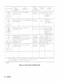
Instruction The instruction documentation symbol. The product
is marked with this symbol when it is necessary for the
Manual
user to refer to the instruction in the manual.
A
The CE93 mark shows compliance with European Community 1993
standards.
The CSA mark is the Canadian Standards Association safety mark.
The ISM1-A mark is a symbol of an Industrial Scientific and Medical
Group 1, Class A product.
vi
Warning
Hazardous voltage always present in this area with instrument
power cord connected t o a c line.
Warning
Hazardous Voltage
Caution
Hazardous electrical shock. Heat sink is live. Disconnect power
supply before servicing.
General Safety
Considerations
Warning
No operator serviceable parts inside. Refer servicing to qualified
personnel. To prevent electrical shock, do not remove covers.
Warning
If this instrument is used in a manner not specified by
Hewlett-Packard Co., the protection provided by the instrument
may be impaired.
Warning
For continued protection against fire hazard replace line fuse
only with same type and rating (3 A 250 V type F). The use of
other fuses or material is prohibited.
Caution
Always use the three-prong ac power cord supplied with this
instrument. Failure to ensure adequate earth grounding by not using
this cord may cause instrument damage.
vii
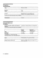
How to Use This
Guide
This guide uses the
following convention:
Documentation
Description
(FRONT-PANEL KEY]
This represents a key physically located on
the instrument.
Display
Text in this font represents FREQUENCY,
MODULATION, and AMPLITUDE displays.
This guide contains the information required to operate, calibrate, and
repair the signal generator to the assembly level. Included are the
following:
a quick overview of the signal generator
examples of typical operation
rn a reference section that describes all operation features
rn explanations of error messages displayed on the signal generator
installation instructions
rn tables of specifications
theory of operation of the signal generator
rn troubleshooting procedures to identify failed assemblies
replaceable part numbers
adjustments required after repair or performance test failure
performance tests to test the instrument to specifications
viii
Contents
1
la
.
.
Operation
Quick Overview . . . . . . . . . . . . . . . . . . .
1. PowerKey . . . . . . . . . . . . . . . . . . .
2 . Display Contrast . . . . . . . . . . . . . . . . .
3. Function and Data Keys . . . . . . . . . . . . .
4 . Increment Set Keys . . . . . . . . . . . . . . .
5 . Knobs . . . . . . . . . . . . . . . . . . . . . .
6. MEMORY . . . . . . . . . . . . . . . . . . . .
7 . Modulation Source . . . . . . . . . . . . . . . .
Operation Examples
Getting Started . . . . . . . . . . . . . . . . . . . .
Operation Examples . . . . . . . . . . . . . . . .
Setting the RF Output Signal . . . . . . . . . . . . .
Setting the Frequency . . . . . . . . . . . . . . .
Setting the Amplitude . . . . . . . . . . . . . . .
Turn on the RF Output . . . . . . . . . . . . . . .
Setting the Modulation . . . . . . . . . . . . . . .
Incrementing or Decrementing the RF Output Signal . .
Preliminary Steps . . . . . . . . . . . . . . . . . .
Using the Knob . . . . . . . . . . . . . . . . . . .
Using the Increment keys . . . . . . . . . . . . . .
Using the Memory Registers . . . . . . . . . . . . . .
Saving Instrument Settings in Register Sequences . . .
Selecting the Sequence . . . . . . . . . . . . . .
Saving Settings in Registers . . . . . . . . . . . .
Checking the Sequence . . . . . . . . . . . . . .
Checking a Different Sequence . . . . . . . . . .
Deleting a Register from the Sequence . . . . . . . .
Selecting the Sequence . . . . . . . . . . . . . .
Deleting a Register . . . . . . . . . . . . . . . .
Renumbering the Registers in a Sequence . . . . . .
Decreasing the Register Number . . . . . . . . . .
Checking the Sequence . . . . . . . . . . . . . .
Inserting a Register in a Sequence . . . . . . . . . .
Saving a New Register . . . . . . . . . . . . . .
Offsetting the RF Output from a Reference . . . . . . .
Setting the Reference Value . . . . . . . . . . . . .
Offsetting the RF Output . . . . . . . . . . . . . .
Turning the Reference Mode Off or On . . . . . . .
Setting a New Reference Value . . . . . . . . . .
Holding the Output Attenuator Range . . . . . . . . .
Set the Amplitude Level . . . . . . . . . . . . . .
Holding the Attenuator . . . . . . . . . . . . . . .
Adjusting the Amplitude . . . . . . . . . . . . . .
1-2
1-2
1-2
1-2
1-2
1-2
1-3
1-3
1a-1
1a-1
1a-2
1a-2
1a-2
1a-3
1a-3
1a-4
1a-4
1a-4
1a-5
1a-6
1a-7
1a-7
1a-7
1a-9
1a-9
1a-11
1a-11
1a-11
1a-13
1a-13
1a-14
1a-15
1a-16
1a-17
1a-17
1a-18
1a-18
1a-19
1a-20
1a-20
1a-20
1a-21
Contents-1
.
lb
Contents2
Operation Reference
Frequency and Amplitude . . . . . . . . . . . . . . . 1b-2
1b-2
1 . Knob . . . . . . . . . . . . . . . . . . . . . .
1b-2
2 . Digit-Select Arrow Keys . . . . . . . . . . . . .
3. REFSET . . . . . . . . . . . . . . . . . . . .
1b-3
Units . . . . . . . . . . . . . . . . . . . . . . .
1b-3
4 . REF ON/OFF . . . . . . . . . . . . . . . . . . . 1b-3
Function . . . . . . . . . . . . . . . . . . . . . . .
1b-4
1. FREQUENCY . . . . . . . . . . . . . . . . . . 1b-4
2 . AMPLITUDE . . . . . . . . . . . . . . . . . . 1b-4
3 . FMAM4M . . . . . . . . . . . . . . . . . . . 1b-4
INCREMENT SET . . . . . . . . . . . . . . . . . . . 1b-5
1 . INCRSET . . . . . . . . . . . . . . . . . . . .
1b-5
Data . . . . . . . . . . . . . . . . . . . . . . . . .
1b-6
1b-6
1 . MHz/dBm . . . . . . . . . . . . . . . . . . . .
Units Conversion . . . . . . . . . . . . . . . . . 1b-6
2 . Backspace . . . . . . . . . . . . . . . . . . . .
1b-6
3 . emf . . . . . . . . . . . . . . . . . . . . . . .
1b-6
4.f . . . . . . . . . . . . . . . . . . . . . . . .
1b-6
Instrument Preset . . . . . . . . . . . . . . . . . . 1b-7
(POWER] @ . . . . . . . . . . . . . . . . . . . .
1b-7
C m - [DEL) . . . . . . . . . . . . . . . . . . . .
1b-7
HP-IB . . . . . . . . . . . . . . . . . . . . . . . .
1b-9
1 . ADRS . . . . . . . . . . . . . . . . . . . . . .
1b-9
2 . LOCAL . . . . . . . . . . . . . . . . . . . . .
1b-9
MEMORY . . . . . . . . . . . . . . . . . . . . . .
1b-10
1.SAV . . . . . . . . . . . . . . . . . . . . . . .
1b-11
2 . REG . . . . . . . . . . . . . . . . . . . . . .
1b-12
3. Register Recall Arrows . . . . . . . . . . . . . . 1b-12
4 . SEQ . . . . . . . . . . . . . . . . . . . . . . .
1b-13
5. DEL . . . . . . . . . . . . . . . . . . . . . .
1b-14
Renumbering the Registers . . . . . . . . . . . . 1b-14
Modulation Source . . . . . . . . . . . . . . . . . . 1b-15
1 . MODON/OFF . . . . . . . . . . . . . . . . . . 1b-16
2 . INT 400 Hz INT 1 kHz . . . . . . . . . . . . . . 1b-16
3. EXTACEXTDC . . . . . . . . . . . . . . . . . 1b-16
4 . 1 kHz + EXT DC . . . . . . . . . . . . . . . . 1b-17
Setting the Modulation Level . . . . . . . . . . . 1b-17
5. MOD INPUT/OUTPUT . . . . . . . . . . . . . . 1b-17
RF OUTPUT . . . . . . . . . . . . . . . . . . . . .
1b-18
1. RFON/OFF . . . . . . . . . . . . . . . . . . . 1b-18
2 . ATTNHOLD . . . . . . . . . . . . . . . . . . . 1b-18
Vernier Ranges . . . . . . . . . . . . . . . . . . 1b-18
3. RFOUTPUT . . . . . . . . . . . . . . . . . . . 1b-19
Rear Panel . . . . . . . . . . . . . . . . . . . . . .
1b-20
1 . 10 MHz REF INPUT and OUTPUT . . . . . . . . . 1b-20
2 . DISPLAY CONTRAST . . . . . . . . . . . . . . . 1b-20
3. AUXILIARY INTERFACE . . . . . . . . . . . . . 1b-21
4 . Line Voltage Connector . . . . . . . . . . . . . 1b-21
5 . HP-IB Connector . . . . . . . . . . . . . . . . . 1b-21
6. TIMEBASEADJUSTandHelpSwitches . . . . . . 1b-21
Remote Interface (Accessory) . . . . . . . . . . . . . 1b-22
1. MODON/OFF . . . . . . . . . . . . . . . . . . 1b-22
2 . RFON/OFF . . . . . . . . . . . . . . . . . . . 1b-22
3. Sequence Selection Arrows . . . . . . . . . . . . 1b-23
4 . Register Recall Arrows . .
Memory Interface (Accessory) .
1. POWER . . . . . . . . . .
2. Copy Arrow Keys . . . .
Making a Copy . . . . . .
3.BUSY . . . . . . . . . . .
.
.
.
.
.
.
. . . . . . . . .
. . . . . . . . .
..........
. . . . . . . . .
. . . . . . . . .
..........
. . lb-23
. . 1b-24
. .
. .
IC. Operation Messages
Front Panel Operation Messages . . . . . . . . . . . .
HP-IB .Command Errors . . . . . . . . . . . . . . .
HP-IB Execution Errors . . . . . . . . . . . . . . . .
HP-IB Device-Specific Errors . . . . . . . . . . . . .
HP-IB Query Errors . . . . . . . . . . . . . . . . . .
Service Messages . . . . . . . . . . . . . . . . . . .
1b-24
1b-25
1b-25
1b-25
1c-1
1c-5
1c-7
1c-7
1c-7
1c-8
2 . Hp-IB Programming
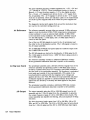
Background . . . . . . . . . . . . . . . . . . . . .
Programming Guidelines . . . . . . . . . . . . . . .
HP-IB Definition . . . . . . . . . . . . . . . . . .
What is Programmable . . . . . . . . . . . . . . .
HP-IB Address . . . . . . . . . . . . . . . . . . .
Error Messages . . . . . . . . . . . . . . . . . . .
Programming Language . . . . . . . . . . . . . . .
Query . . . . . . . . . . . . . . . . . . . . . . .
Advanced Programming . . . . . . . . . . . . . . .
Programming Examples . . . . . . . . . . . . . . . .
Programming RF Frequency . . . . . . . . . . . . .
Programming RF Frequency and FM Modulation . . .
Querying RF Frequency . . . . . . . . . . . . . . .
Programming RF Amplitude . . . . . . . . . . . . .
HP-IB Status Reporting . . . . . . . . . . . . . . . .
External Modulation Input Level Status . . . . . . .
Example: Check the Condition of Modulation Input
(High or Low) . . . . . . . . . . . . . . . . .
Example: Generate a Service Request for External
Modulation Input (High or Low) . . . . . . . .
Reverse Power Protection Status . . . . . . . . . .
Example: Check the condition of the RPP . . . . .
Unspecified Power (Amplitude) Entry Status . . . . .
Example: Check the Condition of Unspecified Power
Entry . . . . . . . . . . . . . . . . . . . . .
HP 8647A SCPI Command Reference . . . . . . . . .
AM Subsystem . . . . . . . . . . . . . . . . . . .
CAL Subsystem . . . . . . . . . . . . . . . . . . .
FM Subsystem . . . . . . . . . . . . . . . . . . .
FREQuency Subsystem . . . . . . . . . . . . . . .
OUTPut Subsystem . . . . . . . . . . . . . . . . .
PM Subsystem . . . . . . . . . . . . . . . . . . .
POWer Subsystem . . . . . . . . . . . . . . . . .
STATUSSubsystem . . . . . . . . . . . . . . . . .
SYSTem Subsystem . . . . . . . . . . . . . . . . .
HP-IB Capabilities . . . . . . . . . . . . . . . . . .
HP-IB Connector Information . . . . . . . . . . . . .
2-1
2-3
2-3
2-3
2-3
2-3
2-3
2-3
2-3
2-4
2-4
2-4
2-5
2-5
2-8
2-9
2-9
2-10
2-11
2-11
2-11
2-12
2-13
2-14
2-14
2-15
2-16
2-16
2-17
2-18
2-19
2-20
2-21
2-22
Contents3
3
.
4
5
.
.
.
.
.
.
.
.
.
.
.
.
.
.
.
.
.
.
. . . . . . . . .
. . . . . . . . .
. . . . . . . . .
. . . . . . . . .
. . . . . . . . .
. . . . . . . . .
. . . . . . . . .
. . . . . . . . .
Specifications
Frequency Specifications . . . . . . . . . . . . . . .
Internal Reference Oscillator . . . . . . . . . . . . .
output . . . . . . . . . . . . . . . . . . . . . . . .
Spectral Purity . . . . . . . . . . . . . . . . . . . .
Frequency Modulation . . . . . . . . . . . . . . . .
Phase Modulation . . . . . . . . . . . . . . . . . . .
Amplitude Modulation . . . . . . . . . . . . . . . .
Modulation Source . . . . . . . . . . . . . . . . . .
Remote Programming . . . . . . . . . . . . . . . . .
Environmental . . . . . . . . . . . . . . . . . . . .
General . . . . . . . . . . . . . . . . . . . . . . .
Regulatory Information . . . . . . . . . . . . . . . .
IS0 9002 Compliant . . . . . . . . . . . . . . . . .
Statement of Compliance . . . . . . . . . . . . . .
Noise Declaration . . . . . . . . . . . . . . . . . .
3-1
3-1
3-2
3-2
3-5
3-5
3-5
3-6
4-2
4-2
4-3
4-3
4-4
4-5
4-5
4-6
4-6
4-6
4-6
4-8
4-8
4-8
4-8
Service
Shipping Your Instrument Back to Hewlett-Packard . . .
Operation Verification Software . . . . . . . . . . . .
5-1
5-2
5a. Theory of Operation
Introduction . . . . . . . . . . . . . . . . . . . . .
Overview . . . . . . . . . . . . . . . . . . . . .
A1 Front Panel . . . . . . . . . . . . . . . . . . .
A2 Power Supply . . . . . . . . . . . . . . . . . .
A3 Motherboard . . . . . . . . . . . . . . . . . .
A4 Reference . . . . . . . . . . . . . . . . . . .
A5 Sig Gen Synth . . . . . . . . . . . . . . . . . .
A6 Output . . . . . . . . . . . . . . . . . . . . .
A7 Attenuator . . . . . . . . . . . . . . . . . . .
5a-1
5a-2
5a-2
5a-3
5a-3
5a-4
5a-4
5a-4
5a-5
.
5b
Contents4
Installation
Unpacking Your Signal Generator
Connecting AC Power . . . . . .
Power Requirements . . . . .
Replacing the Fuse . . . . . .
Turning On the Signal Generator
Connecting to Other Instruments
Storing the Signal Generator . .
Shipping the Signal Generator . .
Troubleshooting Information
Introduction . . . . . . . . . . . . . . . . . . . . .
Troubleshooting Checklist . . . . . . . . . . . . .
AC Mains (line) Fuse Removal . . . . . . . . . . .
To Remove the Fuse . . . . . . . . . . . . . .
Modulation Testpoints and Power Supply LEDs . . .
Power Supply Distribution . . . . . . . . . . . .
. .
. .
. .
. .
. .
5b-1
5b-2
5b-3
5b-3
5b-4
5b-5
.
6.
5c
Service Error Messages
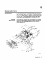
Replaceable Parts
Introduction . . . . . . . . . .
Assembly Replacements . . .
..........
. . . . . . . . . . .
6-1
6-1
7 . Adjustments
Internal Timebase Adjustment . . . . . . . . . . . . .
Recommended Equipment (or equivalent) . . . . . .
Procedure . . . . . . . . . . . . . . . . . . . . .
8
.
7-1
7-1
7-1
Performance Tests
Calibration Cycle . . . . . . . . . . . . . . . . . . . 8-1
8-2
Required Test Equipment . . . . . . . . . . . . . . .
8-3
FM Accuracy Performance Test . . . . . . . . . . .
8-4
FM Distortion Performance Test . . . . . . . . . . .
8-6
AM Accuracy Performance Test . . . . . . . . . . .
8-7
AM Distortion Performance Test . . . . . . . . . . .
8-9
Phase Modulation Accuracy Performance Test . . . .
Phase Modulation Distortion Performance Test . . . . 8-10
Residual FM Performance Test . . . . . . . . . . . . 8-12
Harmonics Performance Test . . . . . . . . . . . . 8-14
Spurious Performance Test . . . . . . . . . . . . . 8-15
DC FM Frequency Error Performance Test . . . . . . 8-16
RF Level Accuracy Performance Test . . . . . . . . . 8-17
CW Frequency Accuracy Performance Test (Option 1E5
8-18
Only) . . . . . . . . . . . . . . . . . . . . . .
8-19
Test Record . . . . . . . . . . . . . . . . . . . .
Index
Contents-5
Figures
2.1 . HP 8647A Status Register Model . . . . . . . . . . .
3.1 . Replacing the Fuse . . . . . . . . . . . . . . . . .
3.2 . Power Cable and Mains Plug . . . . . . . . . . . .
5a.1 . Simplified Block Diagram . . . . . . . . . . . . . .
5b.1 . Removing the Fuse Housing . . . . . . . . . . . . .
8.1 . FM Accuracy Equipment Setup . . . . . . . . . . .
8.2 . FM Distortion Equipment Setup . . . . . . . . . . .
8.3 . AM Accuracy Equipment Setup . . . . . . . . . . .
8.4 . AM Distortion Equipment Setup . . . . . . . . . . .
8.5 . Phase Modulation Distortion Equipment Setup . . . .
8.6 . Phase Modulation Distortion Equipment Setup . . . .
8.7 . Residual FM Equipment Setup . . . . . . . . . . . .
8.8 . Harmonics Equipment Setup . . . . . . . . . . . .
8.9 . Spurious Equipment Setup . . . . . . . . . . . . .
8.10 . DC FM Frequency Error Equipment Setup . . . . . .
8.11 . RF Level Accuracy Equipment Setup . . . . . . . .
8.12 . CW Frequency Accuracy Equipment Setup . . . . . .
2-8
3-3
3-4
5a-1
5b-3
8-3
8-4
8-6
8-7
8-9
8-10
8-12
8-14
8-15
8-16
8-17
8-18
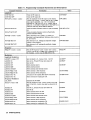
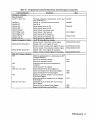
2.1 . Programming Command Statements and Descriptions .
2.2 . Dictionary of Terms . . . . . . . . . . . . . . . . .
2.3 . IEEE 488.2 Capabilities . . . . . . . . . . . . . . .
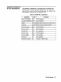
3.1 . Voltage Ranges for Nominal Voltage Values . . . . . .
5a.1 . A1 Front Panel (keyboard) . . . . . . . . . . . . .
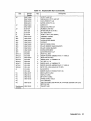
6.1 . Replaceable Parts . . . . . . . . . . . . . . . . . .
8.1 . HP 8647A Test Record . . . . . . . . . . . . . . .
8.2 . HP 8647A Test Record . . . . . . . . . . . . . . .
8.3 . FM Accuracy Performance Test . . . . . . . . . . .
8.4 . FM Distortion Performance Test . . . . . . . . . . .
8.5 . AM Accuracy Performance Test . . . . . . . . . . .
8.6 . AM Distortion Performance Test . . . . . . . . . . .
8.7 . Phase Modulation Accuracy Performance Test . . . .
8.8 . Phase Modulation Distortion Performance Test . . . .
8.9 . Residual FM Performance Test . . . . . . . . . . . .
8.10 . Harmonics Performance Test . . . . . . . . . . . .
8.11 . Spurious Performance Test . . . . . . . . . . . . .
8.12 . DC FM Frequency Error Performance Test . . . . . .
8.13 . RF Level Accuracy Performance Test . . . . . . . . .
8.14 . CW Frequency Accuracy Performance Test (Option 1E5
Only) . . . . . . . . . . . . . . . . . . . . . .
2-6
2-13
2-21
3-2
5a-3
6-2
8-19
8-20
8-21
8-22
8-23
8-25
8-26
8-27
8-28
8-29
8-32
8-33
8-34
Thbles
Contents-6
8-39
1
Operation
“Operation” contains the following information:
Note
1. Operation
Provides a quick overview of the instrument’s
operation.
la. Operation
Examples
Provides examples to help you learn how to operate
the instrument.
lb. Operation
Reference
Provides quick access to information about each of
the instrument’s functions.
Operation
Messages
HP-IBremote operation messages.
Provides information about both front-panel and
For information about service messages numbered 500 and above,
refer to Chapter 5c, “Service Error Messages.”
Operation
1.1
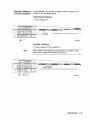
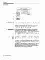
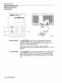
Quick Overview
1 2 3 4
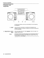
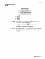
1. Power Key
6
7
Press (
m
to
)power-up the instrument. The instrument powers up
to the same state it was in when power was turned off, except that
the RF output will be turned off press the1
-Jf
key to turn it
on.
2. Display Contrast
Display contrast is an adjustment that is located on the rear panel.
It allows you to adjust contrast for the front-panel display. Turn
the adjustment to optimize the display for viewing it from above,
below, or straight on. If the display is blank, first attempt to adjust
the display contrast adjustment before returning the instrument for
service.
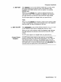
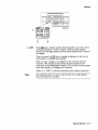
3. Function and Data
Keys
The keys in the FUNCTION and DATA blocks allow you to enter
values for setting the frequency, amplitude, and modulation level of
the RF output signal.
4. Increment Set Keys
5. Knobs
When you press a FUNCTION key, that function becomes the active
function. Press) TES - [
to view or change the increment value for
the active function. Press the
or (TD key at any time to change the
active function setting by the increment value.
The knobs are always active when the instrument is in local (front
panel) control. Turn them to increase or decrease the frequency or
amplitude of the RF output. Press @ or
next to each knob, to
adjust the knob’s resolution.
a,
Press, ) TE (-S
next to each knob, to set the displayed value as the
reference value and turn on the reference mode. Press CREF ON/OFF)
turn on and off the reference mode without changing the reference
value. When the reference mode is on, the displayed value indicates
the offset between the reference value and the RF output signal.
1-2 Operation
0
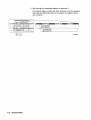
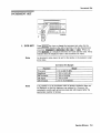
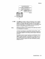
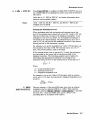
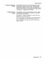
6. MEMORY
Memory registers allow you to save instrument set-ups and recall
them whenever you wish. Press
and enter a two-digit register
number to save the instrument's current settings. To recall the
settings, press
and enter the register number. The arrow keys
allow you to recall registers in numerical sequence. You can arrange
your registers in up to ten different sequences.
The number of the currently selected sequence and the last register
selected are always displayed in the lower left corner of the display
to help you keep track of where you are in your testing process.
The memory register examples provided in Chapter la, "Operation
Examples," show you how to create a sequence and how to delete or
add registers in your sequence.
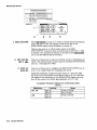
7. Modulation Source
Press [MOD
ON/OFF) to turn on or off the modulation source. Press
or 1
-(
to select one of the internal source tones
for modulating the RF output signal. These tones are also available
as an output signal at the MOD INPUT/OUTPUT port when they are
selected. Press
or [EXTI to ac- or dc-couple an external
audio source via the MOD INPUT/OUTPUT port.
L
m
]
[m)
Press ( i k k + EXT DC) to frequency modulate the RF signal with
the internal 1 kHz tone and an external source at the same time.
(Additional internal plus external modulation capabilities are available
for HP-IB operation.)
Operation
1-3
la
Operation Examples
This section contains operating examples to help you learn how to
operate the signal generator. These examples can be performed
without any additional equipment.
Gmetting Started
Operation Examples
If this is the first time you have operated this instrument, perform
each of the following examples for a quick introduction to general
operation. After you have completed the examples, try operating the
instrument’s remaining functions on your own. If you have trouble
or want additional information on a function, refer to Chapter lb,
“Operation Reference.” If a message is displayed that you do not
understand, refer to Chapter IC, “Operation Messages.”
1. Setting the RF Output Signal
2. Incrementing or Decrementing the RF Output Signal
3. Using the Memory Registers
4. Offsetting the RF Output from a Reference
5 . Holding the Output Attenuator Range
1
4
2
3
5
Operation Examples
la-1
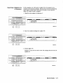
Setting the RF
Output Signal
In this example, you will set the frequency, amplitude, and modulation
level of the RF output signal.
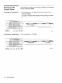
Setting the Frequency
1. Set the frequency to 100 MHz using the keys shown below the
instrument diagram.
If you make a mistake while entering a value, press
to correct
it.
functl .drw
Setting the Amplitude
2. Set the amplitude to -100 dBm.
funct2.dnv
la-2 Operation Examples
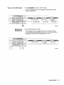
Turn on the RF Output
3. Press @KjiEF]
to turn on the RF output.
RF OFF is displayed below the amplitude setting when the RF
output is turned off.
MODULATION
100.00000 MHz
-
AMPUTUDE
FM 3.00 kHz
rlJnd3.dlw
Setting the
Modulation
4. Set the FM deviation to 3 kHz.
The modulation rate is displayed below the deviation setting.
Use the MODULATION SOURCE keys when you wish to select a
modulation source and turn modulation on or off.
Operation Examples
1a-3
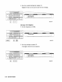
Incrementing or
Decrementing the
RF Output Signal
Preliminary Steps
In this example, you will increment the amplitude and frequency of
the RF output signal.
1. If they are not already set, set the frequency to 100 MHz, and the
amplitude to -100 dBm.
FREQUENCYi -
MODULATION
-
AMPUT
Incrl.drw
Using the Knob
2. Increment the amplitude using the knob.
Press
or
when you wish to adjust the increment resolution.
100.00000 MHz
l a - 4 Operation Examples
-101.0 dBm
Using the Increment
keys
3. Enter a frequency increment of 25 kHz.
The $ symbol is displayed when you press) _TE (-S
to indicate
that the displayed value is the increment set value.
4. Increment the RF output frequency in 25 kHz steps.
The increment keys affect the last FUNCTION selected
(FREQUENCY, AMPLITUDE, FM, AM or 9M).
i
FREOUENCY
- -
100.02500 MHz
MODULATION
.
AMPLITUDE
-101.0 dBm
J
m
incr4.d~
Operation Examples
la-5
Using the Memory
Registers
The memory register examples show you how to create a sequence of
registers, delete a register from that sequence, renumber the registers
in the sequence, and insert a new register in the sequence.
Up to 10 register sequences can be-defined (0 through 9). A sequence
can contain up to 100 registers (00 through 99). There are a total of
300 registers available in the instrument. The registers can be used
in the sequences in any combination (such as 10 sequences of 30
registers each, or 3 sequences of 100 registers each) as long as the
total does not exceed 300 registers. It is not possible to have all 10
sequences each contain 100 registers as that would be 1000 registers.
8,
tl
JREG 99
1 a-6 Operation Examples
300REG
Saving Instrument
Settings in Register
Sequences
In this ten step example, you will use the memory keys to create
a sequence containing three registers. Each register will contain a
different frequency setting.
Selecting the Sequence
1. Select sequence 0.
If there are registers saved in sequence 0, the message shown
in the display below will not appear. Note that the steps in this
example will cause the settings in registers 00, 01, and 02 of
sequence 0 to be changed.
regseql .dm
Saving Settings in Registers
2. Set the frequency to 10 MHz.
(
,
,
,
I
.
]
3. Save the instrument settings in register 00.
10.00000 MHz
SEQ 0 REG 00
4. Set the frequency setting to 11 MHz.
Operation Examples
la-7
regseq4.d~
5. Save the instrument settings in register 01.
regseq5.d~
6. Set the frequency to 12 MHz.
1a 4
Operation Examples
7. Save the instrument settings in register 02.
p-
FREQUENCY
,
-
MODULATION
'
12.00000 MHz
SEQ 0 REG 02
-
AMPLITUDE-
Checking the Sequence
8. Recall the registers in sequence 0.
a
The
and @J keys recall registers or sequences depending on
which key was pressed last
or ISEQ_)).
(m
10.00000 MHz
regseq8.d~
Checking a Different Sequence
9. Select sequence 1.
Operation Examples
1a-9
10. Step through the registers in sequence 1 if there are registers
saved in it.
Note
Sequence 1 does not contain the settings you saved in sequence
0. The instrument enables you to save different settings in each
sequence to create up to ten different sequences for your testing.
Remember when you save or recall a register, be sure that the correct
sequence is also selected.
SEQ 1 REG 00
req0.dnv
la-10
Operation Examples
Deleting a Register
from the Sequence
In this example, you will delete a register from the sequence you
created in the preceding example.
Selecting the Sequence
1. Select sequence 0.
\f
FREQUENCY- '
MODULAllON
-
AMPLITUDE
SEQ 0
L
1
d%lregO.drw
Deleting a Register
2. Delete register 01 from sequence 0.
Note
The contents of the register are recalled when it is deleted. This
allows you to resave the contents if you need to.
FREQUENCY
- MODULATION
AMP
delregl .drw
Operation Examples
la-1 1
3. Step through the remaining registers in sequence 0.
The deleted register number has been removed from the sequence.
Note that the instrument does not renumber the registers when
one is deleted.
delreg2.d~
1a.12
Operation Examples
Renumbering the
Registers in a
Sequence
In this example, you will eliminate the skip from register 00 to register
02 in sequence 0 caused when you deleted register 01 in the previous
Decreasing the Register Number
1. Delete register 02.
The settings saved in register 02 are recalled when it is deleted.
numseql.drw
2. Save the settings from register 02 into register 01.
Operation Examples
la-13
Checking the Sequence
3. Step through the register sequence.
12.00000 MHz
10.00000 MHz
SEO 0 REG 00
Note
la-14
Operation Examples
In this example, you renumbered one register. When you need to
renumber two or more registers, use
instead of
to recall
each register until you get to the last register in the sequence, then
use (DELI.
a
Inserting a Register in
a Sequence
In this example, you will insert a register into the sequence you
created in the previous example. The process involves incrementing
each register number that comes after the point in the sequence
where you wish to insert a register.
1. Recall the last register in sequence 0.
12.00000 MHz
SEQ 0 REG 01
J
imeql .dm
2. Save the recalled settings into register 02.
insseu2.d~
3. Recall register 00.
Register 01 can now be used to save the settings that are saved in
register 00.
10.00000 MHz
SEQ 0 REG 00
Operation Examples
la-15
4. Save the recalled settings into register 01.
Register 00 can now be used to save the new settings.
insseq4.d~
Saving a New Register
5. Set the frequency to 8 MHz.
6. Save the settings in register 00.
Press
ato check the new sequence.
8.00000 MHz
SEQ 0 REG 00
la-16 Operation Examples
Offsetting the RF
Output from a
Reference
Setting the Reference
Value
q@
In this example, you will enter an RF output frequency, set it as the
reference value, and then offset the RF output frequency 10 MHz
below the reference value.
1. Set the frequency to 500 MHz.
I1
0
0/ u
0 0 0 0
-
1
500.00000 MHz
ref1.dnv
2. Set 500 MHz as the reference frequency.
The A symbol appears in the display to indicate that the reference
mode is selected. The output frequency is still 500 MHz.
Operation Examples
la-17
Offsetting the RF
output
3. Offset the output frequency 10 MHz below the reference
frequency.
You can enter in the offset value directly, or use the knob or
and
keys.
a
Attention!
In the reference mode, the output frequency equals the reference
frequency k the displayed offset frequency.
Turning the Reference Mode Off or On
4. Turn-off the reference mode to display the actual output
frequency.
490.00000 MHz
5. Turn-on the reference mode without changing the reference
frequency.
FREQUENCY
- 1
- 1O.OOOOOnMHz
la-1 8 Operation Examples
MODULATION
-
AMPLITUDE
6. Change the displayed units to kHz.
Note that for amplitude, reference settings are displayed in dB
units only.
Setting a New Reference Value
7. Set the current output frequency as the new reference frequency
at any time.
ref7.d~
Operation Examples
la-19
Holding the Output
Attenuator Range
Set the Amplitude
Level
In this example, you will hold the output attenuator so it does not
change ranges when you change the amplitude setting. This will
prevent attenuator range changes from affecting the output signal.
1. Set the amplitude level to -82 dBm.
I
-82.0 dBm
am1drw
Holding the
Attenuator
2. Hold the attenuator at this setting.
\f
FREOUENCY
- MODULATION
AMPLITUDE
-82.0 dBm
HOLD
\
la-20 Operation Examples
J
Adjusting the
Amplitude
3. Adjust the amplitude setting.
Now amplitude changes do not cause the attenuator to change its
range setting. Consequently, amplitude changes are limited to the
range provided by the instrument's vernier. For information about
the instrument's vernier ranges, refer to Chapter lb, "Operation
Reference. '
Operation Examples
la-21
Ib
Operation Reference
This chapter describes each of the instrument’s functions including all
of the front panel keys, the rear panel connectors, and the optional
remote interface and memory interface. This information is presented
in the same functional groups as the front panel key functional
groupings.
Operation Reference
1b-1
Frequency/Amplitude
Frequency and
Amplitude
1
2
3
4
ireqkeys.dm
The knob and reference set keys work similarly for both frequency
and amplitude.
1. Knob
2. Digit-Select Arrow
Keys
Note
lb-2 Operation Reference
Turn the knobs to increment or decrement the frequency and
amplitude settings. The knobs are always active when the instrument
is in local operation.
Press these digit-select arrow keys (@
changed with the knob.
a)
to select the digit to be
The knobs increment the selected digit only. For information about
incrementing by an arbitrary value using the increment set keys, see
“Increment Set” in this chapter.
Frequency/Amplitude
3. REF SET
Press [REF)to turn on the reference mode and to set the current
RF output setting as the reference value. The reference value
is stored in non-volatile memory until you replace it by pressing
(
R
E
F
S
E
T
again.
)
When you press, ) TE (-S
the A symbol is displayed between the
value and the units. When A appears, the displayed value indicates
the offset between the reference value and the RF output signal.
The RF output signal is not changed when you press this key.
Units
When you press (REF]for frequency, values can be entered in MHz
or kHz. For amplitude, values can be entered in any of the amplitude
units provided, but they are displayed in dB only.
4. REF ON/OFF
Press [REF ON/OFF]
to turn off the reference mode if it is on, or to turn
on the reference mode without changing the reference value.
When you turn on the reference mode, the displayed value indicates
the offset between the reference value and the current RF output
setting.
The RF output signal is not changed when you press this key.
Output Power
Trouble?
If the RF output power seems too low, look for A in the display
between the power level value and the dB indicator. The A tells you
that reference mode is turned on. The displayed value is not the
output power level; it is the offset between the reference value and
the output power. To exit the reference mode, press CREF O N / O F F ~ . You
can then reset the output power to the desired level.
Operation Reference
1b-3
Function
Function
1
1. FREQUENCY
The RF output frequency range is 250 kHz to 1000 MHz. When
making frequency changes, the instrument does not turn off the RF
output.
Frequency switching typically takes less than 120 ms. Worst case
conditions occur for changes which cross the instrument’s two
frequency band edges (249 MHz and 501 MHz).
2. AMPLITUDE
3. FM
AM
4M
The RF output amplitude range is -136 dBm to + 10 dBm with
over-range to + 13 dBm. When making amplitude changes, the
instrument does not turn off the RF output. The electronic attenuator
provides rapid amplitude changes. The period of any over- or
under-ranging that may occur during level transitions is typically less
than 30 ms.
Press IFM_) to set the peak deviation for frequency modulation. Then
use the data entry keys to enter the desired value of deviation. The
values allowed depend on the RF frequency selected. See Chapter 4,
“Specifications” for peak deviation specifications.
Press IAM) to set the amplitude modulation range. Then use the data
entry keys to set the desired value of range. Values from 0 through
100% are allowed.
Press @
K
Jto set the peak deviation for phase modulation. Then use
the data entry keys to enter the desired value of deviation. The
values allowed depend on the RF frequency selected. See Chapter 4,
“Specifications” for peak deviation specifications.
lb.4
Operation Reference
Increment Set
INCREMENT SET
incrkays.dw
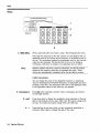
1. INCR SET
Press
J-RCNI (
to view or change the increment set value for the
currently active function (the active function is the last function key
you press; I
-],
,I-[
or
When you
press @FETSETf)J, is displayed between the value and the units. The $
indicates that the displayed value is the increment set value.
m,m),m).
Note
An increment value cannot be set for the knobs or the memory recall
arrow keys.
Function
Frequency
Amplitude
FM Deviation
AM Depth
4M Deviation
Note
Range
1 Hz to 999.75 MHz
> 0.0 to 149.0 dB
> 0.0 to 100 kHz
> 0.0 to 100%
>O.O to 10.0 Radians
It is possible to set an increment value of greater resolution than can
be displayed or than the hardware can respond to. However, the
instrument records each arrow key press and will respond after the
appropriate number of presses.
Operation Reference
lb-5
Data
Data
1
2
4
1. MHz/dJ3m
Press a units key after you enter a value. This terminates the entry.
Note that the units keys in the left column are each labeled with an
amplitude unit on the bottom and a frequency or modulation unit on
the top. The instrument applies the appropriate unit for the function
value you are entering. The bottom key in the row for instance,
terminates a q5M entry in radians or an amplitude entry in dBpV.
~~
Note
~~
Memory register selections, sequence selections, and HP-IB address
entries do not require a units key to terminate the entry. These
entries are automatically terminated after the last digit is entered.
Units Conversion
You can change the units of the displayed frequency or amplitude
value by selecting the FUNCTION (frequency or amplitude) and then
pressing a units key. The instrument will convert the displayed value
to the equivalent value for the units key you pressed.
2. Backspace
3. emf
4.
1b-6 Operation Reference
Press [--1when entering a numeric value to backspace and remove
the last digit entered.
Press these keys to display the amplitude value indicated on the key
label in electromotive force units. Emf is the RF output voltage with
no load. I t is twice the output voltage with a 50 ohm load.
Press this key at any time while you are entering an amplitude or
reference offset value to change the sign of the value.
~
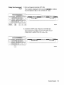
Instrument Preset
Instrument Preset
(
E
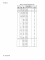
) Turn the instrument on while pressing the backspace key (@) to
perform an instrument preset. The instrument will power up to
factory-defined settings-shown in the following table. Save &d recall
registers are not affected by this operation.
(m
(DEL)
)
Note
Turn the instrument on while pressing the memory (DEL) key to
perform a clear memory. This function erases all savehecall registers,
sets the HP-IB address to 19, and performs an instrument preset
where the instrument powers up to factory-defined settings shown in
the following table.
This will cause an error message to appear on the display:
627 Battery RAM f a i l u r e : memory l o s t . This is normal.
Operation Reference
1b-7
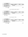
Instrument Preset
Instrument Preset Settings
0.0 MHz
Reference
I
4M
Increment
Input
I
0.1%
Internal
Frequency
coupling
Attenuator
1 b.8
Operation Reference
Deviation
1.0 radians
Increment
0.1 radians
coupling
Off
I
i =
hplbkeya.dm
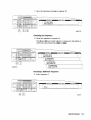
1
2
1. ADRS
Press (ADRS] to view the instrument's HP-IB address setting in the
second line of the FREQUENCY display.
To change the address, press (ADRS) and a two-digit number. For
example, enter 01 to set the address to 1.
Acceptable HP-IB addresses are 00 through 30.
2. LOCAL
Press (J5'CT) to return to front-panel operation when the instrument
has been set for remote (HP-IB) operation. The SEQ and REG fields
will replace the HP-IB status indications in the second line of the
FREQUENCY display when the instrument is returned to local
operation.
Operation Reference
lb-9
Memory
MEMORY
The memory keys allow you to save instrument settings into memory
registers and recall the registers in a numeric sequence.
Up to 10 register sequences can be defined (0 through 9). A sequence
can contain up to 100 registers (00 through 99). There are a total of
300 registers available in the instrument. The registers can be used
in the sequences in any combination (such as 10 sequences of 30
registers each, or 3 sequences of 100 registers each) as long as the
total does not exceed 300 registers. It is not possible to have all 10
sequences each contain 100 registers as that would be 1000 registers.
goo n
SEQ 9
\I-
300 REG
REG 99
MEMORY key entries are automatically terminated after you enter the
last digit. Register key entries ( @, (DEL), and
require two
digits. Sequence key entries
require one digit.
(m)
1b.10
Operation Reference
m),
Memory
2
1. SAV
3
Press (SAVI and a register number (00 through 99) to save the current
operating settings in a memory register. All front-panel settings
except the knob digit positions and the HP-IB address will be saved in
the register.
When you press the (SAVI key, a message is displayed to tell you the
total number of registers still available.
When you save a register, it is assigned to the currently selected
sequence. (The number of the selected sequence appears in the
second line of the FREQUENCY display.) You can only recall a register
when the sequence it is assigned to is selected.
(Refer to “4. SEQ” for further information about register sequences.)
Note
The instrument does not have a copy function for saving registers
from one sequence to another.
Operation Reference
lb-11
Memory
2. REG
CREGJ
Press
and a register number (00 through 99) to recall the
operating settings saved in that register.
The number of the last register recalled appears in the display along
with the number of the currently selected sequence.
You can only recall registers from the currently selected sequence.
To recall a register from another sequence you must first select the
sequence using the
key.
3. Register Recall
Arrows
The recall )
&f and keys can be used to select sequences or recall
registers. The last key pressed (SEQor REG) determines which field is
affected by the arrow keys.
(Refer to “4.SEQ” for further information about register sequences.)
lb-12 Operation Reference
Memory
memkeyl .drw
4
4. SEQ
Press (SE91 and a sequence number (0 through 9) to select a register
sequence. When you select a sequence, the number of the sequence
appears in the display along with the number of the first register
saved in the sequence. The instrument is set to the operating settings
saved in the first register. If no registers have been saved in the
sequence, a message is displayed to let you know.
~
Note
~
Selecting the sequence you are currently in is a quick way to return
to the beginning of the sequence.
A sequence can include up to 100 registers (00 through 99). (There
are a total of 300 registers available in the instrument.) Registers are
automatically assigned to the currently selected sequence when they
are saved.
The registers saved in any given sequence are independent from the
registers in any other sequence. This allows you to create up to 10
different register sequences. Consequently, it is possible to have up
to ten registers with the same number (for example, REG 01) each
assigned to a different sequence and each with different operating
settings saved in it.
Operation Reference
lb-13
Memory
5 . DEL
Note
Press (DEL) and a register number (00 through 99) to delete that
register. The specified register is deleted from the currently selected
sequence only; registers in other sequences you have set up are not
affected. After you have deleted a register, you will not be able to
recall that register number until you have saved operating settings in
it again.
The register number is immediately deleted from the sequence when
the delete entry is completed. However, the settings contained in the
register are recalled when you delete the register so you can re-save
the settings if you need to.
Renumbering the Registers
If you use the arrow keys to recall the registers in sequence, the
deleted register number will be skipped. If you wish to eliminate the
skip, you can do so by moving each register following the deleted
register back one register number. To delete an entire sequence,
delete each register in the sequence.
lb-14 Operation Reference
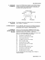
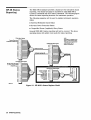
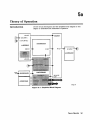
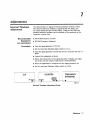
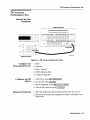
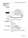
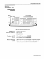
Modulation Source
Modulation Source
blkdag.drw
Modulation Source Paths (the 1 kHz path is highlighted)
Operation Reference
lb-15
Modulation Source
MODULATIONSOURCE
2
4'
1. MOD ON/OFF
\
\ b-
modskeys.dm
3
5
Press (MOD ONIOFF) to turn on or off the currently-selected modulation
mode (AM, FM, or $M). OFF appears in the second line of the
MODULATION display when modulation is turned off.
This key also turns on or off the audio output at the MOD
INPUT/OUTPUT connector when an internal source (400 Hz or 1 kHz)
is selected. The operation of this key is the same as the [MOD ON/OFF)
key on the HP 83300A Remote Interface.
2. INT400Hz
INTlkHZ
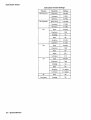
3. EXTAC
EXT DC
Press one of these keys to select an internal source for modulating the
carrier. The selected source is also output at the MOD INPUT/OUTPUT
port as a 1 Vpk signal into 60061.
Press one of these keys to configure the MOD INPUT/OUTPUT port as
an ac- or dc-coupled input for modulating the carrier.
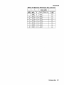
Calibrated modulation requires an audio source of 1 Vpk into 600hl.
For audio source frequencies of less than 10 kHz, a H I or LO indicator
will appear in the second line of the MODULATION display when the
level of the source is not within approximately &5% of 1 Vpk.
Acceptable Frequency Ranges for an External Audio
Source
Modulation
FM, 4M
AM
1b.16
Operation Reference
1
Coupling
EXT AC
EXT DC
EXT AC
EXT DC
Range
20 Hz to 75 kHz
DC to 75 kHz
20 Hz to 25 kHz
i
Modulation Source
4. 1 kHz
+ EXT DC
Press [I kHz + EXT DC) to configure the MOD INPUT/OUTPUT port as a
DC coupled input for modulating the carrier along with the internal 1
kHz source.
(Refer also to “ 3 . EXT AC EXT DC” for further information about
operation and acceptable ranges.)
Note
1 kHz + EXT AC, 400 Hz
available only via HP-IB.
+
EXT DC, and 400 Hz
+ EXT AC are
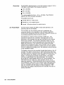
Setting the Modulation Level
When modulating with both an internal and external source, the
level of the external source should not exceed 0.5 V peak or 0.5 Vdc.
This level will provide one half of the displayed modulation. To set
modulation to the level you desire, set the displayed modulation to
two-thirds of the desired setting. The external source, set to 0.5 V
peak or 0.5 Vdc, will provide the additional one-third of the desired
setting (one-half of the instrument’s setting).
For example, to set up the modulation for 3 kHz of FM deviation, set
the instrument for 2 kHz of FM. The external source, set to 0.5 V
peak, will provide another 1 kHz of deviation.
If the external source is set to less than 0.5 V peak, the modulation
level provided by the source will be less than one-half of the
displayed resolution. The following equation may be helpful for
determining the appropriate modulation level setting for the
instrument when the level of the external source is less than 0.5 V.
- =A
l+E
D
Where:
A
E
D
=
=
=
Actual modulation level
External source level
Displayed modulation level
For example, to set up for 3 kHz of FM deviation with an external
source set to 0 . 3 V peak, the instrument’s displayed modulation level
would be:
3kHz
1 + 0.3V
=
2.3kHz
This port outputs a 1 Vpk (into 6000) audio tone when an internal
source is selected (400 Hz or 1 kHz). When external
I N ~ U T / O U modulation
~ ~
[ETET] or [I kHz + EXT DC)), it provides
coupling is selected c1(-,
the input for a 1 Vpk (into 600Q) audio source. (Refer to the
preceding table for acceptable audio ranges.)
5. MOD
Operation Reference
lb-17
RJ? Output
RF OUTPUT
2’
1. RF ON/OFF
3’
Press I
)
to turn the RF output signal on or off. RF OFF
appears in the second line of the AMPLITUDE display when the
output signal is off.
The instrument turns off the output signal by switching in the
maximum output attenuation (130 dB) and setting the vernier to
its lowest setting. This results in approximately 170 dB of carrier
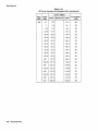
isolation.
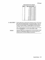
2. ATTN HOLD
Press
1-(
to hold the electronic step attenuator at its current
setting. HOLD appears in the second line of the AMPLITUDE display
when the attenuator hold function is on.
When the attenuator hold function is on, amplitude adjustments are
limited to the range of the instrument’s vernier. The vernier provides
0.1 dB per step adjustment resolution across its specified 10 dB range.
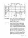
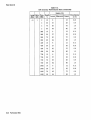
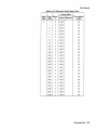
Vernier Ranges
The following table (10 dB Specified Vernier Ranges) provides the
upper and lower limits of each vernier range. The instrument’s
amplitude setting when you press the
key determines
which vernier range is used.
)-c
The vernier is allowed to over-range and under-range beyond the
limits shown in the table when (ATTN]
is selected. However,
amplitude settings that exceed the limits may not provide output
levels that are within the accuracy specifications of the instrument.
1b.18
Operation Reference
RF output
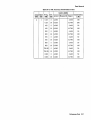
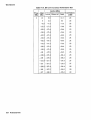
10 dB Specified Vernier Ranges
Range
1
2
3
4
5
6
7
8
9
10
11
12
13
14
3. RF OUTPUT
Upper and Lower Limits
+ 10.0 dBm to -5.9 dBm
-6.0 dBm to -15.9 dBm
-16.0 dBm to -25.9 dBm
-26.0 dBm to -35.9 dBm
-36.0 dBm to -45.9 dBm
-46.0 dBm to -55.9 dBm
-56.0 dBm to -65.9 dBm
-66.0 dBm to -75.9 dBm
-76.0 dBm to -85.9 dBm
-86.0 dBm to -95.9 dBm
-96.0 dBm to -105.9 dBm
-106.0 dBm to -115.9 dBm
-116.0 dBm to -125.9 dBm
- 126.0 dBm to - 136.0 dBm
The RF output port is reverse-power protected to 50 W or 25 Vdc into
500. When the instrument senses a reverse-power signal, it turns the
RF output off, the step-attenuator to maximum attenuation, and the
vernier to its lowest setting. A message appears in the second line of
the display when the reverse-power protection has been activated.
After you have removed the reverse-power signal from the RF output,
press the j1
key to turn the output signal on again.
Caution
Applying a signal source exceeding 50 W or 25 Vdc into 509 to the RF
output port or maintaining a signal source at the RF output for an
extended period of time may damage the instrument.
Operation Reference
lb-19
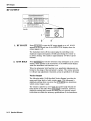
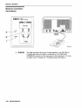
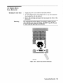
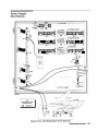
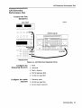
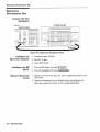
Rear Panel Operation
Rear Panel
I'
1. 10 MEtz REF INPUT
and OUTPUT
2. DISPLAY
CONTRAST
lb-20 Operation Aeference
2
3
4
5
6
These connectors provide the input and output ports for the
instrument's timebase reference. The instrument will lock to a 2 MHz,
5 MHz, or 10 MHz external reference source connected to the input
that is within f 5 ppm. When the internal timebase is being used, the
output connector provides a 10 MHz, 1 Vrms level signal.
This knob controls the front-panel display contrast. Display contrast
can be optimized for viewing the display from above, below, or
directly in front of it.
Rear Panel Operation
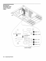
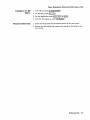
3. AUXILIARY
INTERFACE
Connect the HP 83300A Remote Interface or the HP 83301A Memory
Interface to this connector for operation with the instrument. Refer
to “Remote Interface” and “Memory Interface” in this section for
information about operating these devices.
TX Data (output)
+5 Volts
RX Data (input)
Ground
\
CTS (input)
4. Line Voltage
Connector
5. HP-IB Connector
6. TIMEBASE
ADJUST and Help
&,itches
RTS (output)
For information about the line voltage connector or fuse replacement,
refer to Chapter 3, “Installation.”
This is an IEEE 488.1-1987 connector for controlling the instrument
via an external controller. For information about HP-IB operation of
the instrument, refer to Chapter 2, “HP-IBProgramming. ’
Position one of this switch (labeled “TIMEBASE ADJUST”) places
the instrument in the timebase adjustment mode. For the timebase
adjustment procedure, refer to Chapter 7, “Adjustments.’
Position two of this switch (labeled “NOT USED”) is the switch which
allows you to turn off the following error messages:
001
No e x t e r n a l dc coupling for PM
002
Modulation exceeds d e v i a t i o n range
004
Invalidunits selection
005
Increment value e n t r y o u t of range
006
End of increment range
007
Entered value out of range
008
Amplitude exceeds s p e c i f i e d r a n g e
010
End of knob range
011
Amplitude exceeds A T T N H O L D l i m i t s
012
No e x t e r n a l dc coupling for AM
013
AM u n s p e c i f i e d above 4 dBm
014
AM u n s p e c i f i e d a t or below 1.5 MHz
For more information about these messages, refer to Chapter IC,
“Operation Messages. ”
Operation Reference
lb.21
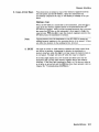
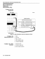
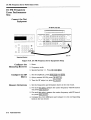
Remote Interface
Remote Interface
(Accessory)
AUXILIARY
INTERFACE
1
2
4
3
1. MOD ON/OFF
Press [MOD ON/OFF) to turn on or off all modulation (internal and
external) to the RF carrier. When modulation is turned off, the
LED above the key is off and OFF appears in the second line of the
instrument’s MODULATION display.
This key also turns on or off the audio output at the MOD
INPUT/OUTPUT port when an internal source (400 Hz or INT 1 kHz) is
selected.
2. RF ON/OFF
Press)-(
to turn the RF output signal on or off. When the RF
output signal is turned off, the LED above the key is off and RF OFF
appears in the second line of the instrument’s AMPLITUDE display.
There is approximately 170 dB of carrier isolation when the output is
Off.
lb-22 Operation Reference
Remote Interface
3. Sequence Selection
Arrows
4. Register Recall
Arrows
a a
Press
or
to select the next or previous sequence of registers.
The sequences are selected in numeric order. The number of the
selected sequence appears in the second line of the FREQUENCY
display. When a sequence is selected, the first register in the sequence
is recalled. When a sequence is selected that has no registers saved in
it, two dashes (- -) will appear in the REG field.
a
to recall the operating settings saved in the registers
or
Press
in the currently selected sequence. The number of the last register
accessed appears in the REG field.
If two dashes (- -) appear in the REG field, a sequence that has no
registers saved in it has been selected.
After the last register in the sequence has been recalled, the register
count will begin again at the first register saved in the sequence.
(Refer to "MEMORY" in this section for further information about
register sequences.)
Operation Reference
1b.23
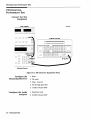
Memory Interface
Memory Interface
(Accessory)
AUXIURY
INTERFACE
1. POWER
lb.24
Operation Reference
This light indicates that power is being supplied to the HP 83301A.
It should light when the cable is connected to the AUXILLARY
INTERFACE connector on the rear panel of the instrument. If it does
not light, refer to Chapter 5b, “Troubleshooting Information. ”
Memory Interface
2. Copy Arrow Keys
Press these keys to initiate a copy of the memory registers between
the instrument and the HP 83301A. After the instrument has
successfully completed the copy, it will display a message to let you
know.
Making a Copy
When the HP 83301A is connected to the instrument, press the @) to
copy all of the memory registers saved in the instrument into the
HP 83301A's memory. After you have pressed an arrow key, you must
also press the (SAV) key on the instrument's front panel to begin the
to copy the memory registers stored in the
copy process. Press the
HP 83301A into the instrument's memory.
Note
Copying memory into the instrument or the HP 83301A causes any
existing memory registers in the receiving device to be erased. It does
not effect the memory in the sending device, however.
3. BUSY
This light is turned on while memory registers are being copied from
one device to another. Attempting to operate the instrument or
memory interface while this light is on may cause the memory data to
be corrupted. The light will turn off when the copy is complete.
If the Busy light flashes for a few seconds and then turns off, the
instrument did not find valid memory register data in the memory
interface. If the Busy light continues to flash, or if it does not turn on
at all after an arrow key and the ISAV) key have been pressed, refer to
Chapter 5b, "Troubleshooting Information.
Operation Reference
lb-25
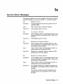
IC
Operation Messages
This chapter provides descriptions for both front panel and HP-IB
operation messages. (For information about service messages,
numbered 500 and above, refer to Chapter 5c, "Service Error
Messages.
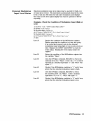
Front Panel
Operation
Messages
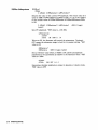
SEQ X SAVE
- - XXX r e g i s t e r s a v a i l a b l e
This message is displayed when the
key is pressed to
inform you of how many registers are still available. If
a register is available, enter the two-digit number of the
register you wish to save.
SEq XREG--XXhas not beensaved
This message is displayed when an attempt is made to recall
a register that has not been saved in the sequence. Check to
be sure that the appropriate sequence is selected and that
you have entered the correct register number.
SEQ XDEL--Enternumberto d e l e t e
This message is displayed when the (DEL) key is pressed.
Enter the number of the memory register you wish to
delete. When a register is deleted, the settings saved in it
are erased and the register number is removed from the
sequence.
SEQXhasnoregisters s a v e d i n i t
This message is displayed when a sequence is selected that
has no registers saved in it. If you wish to save registers in
the sequence, set-up the instrument, press the ISAV) key, and
enter a two-digit register number.
001
No e x t e r n a l d c coupling f o r PM
This message is displayed when PM is selected and
kHz + EXT DC) is also selected. DC coupling
of an external source is not possible for PM. If you press
(1 kHz + EXT DC] you will actually get 1 kHz and external ac.
Or, select [EXT] coupling for PM. Additional internal plus
external modulation capabilities (such as [I kHz + EXT AC))
are available through HP-IB control of the instrument; refer
to Chapter 2, "HP-IB Programming.
(EXTDC)or (1
Operation Messages
1c.l
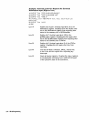
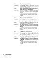
002
Modulation exceeds d e v i a t i o n r a n g e
This message is displayed when modulation is set to a level
that exceeds the operating range of the instrument. This
condition occurs when a modulation level is entered that is
out-of-range for the current RF frequency setting, or when
the RF frequency setting is changed and the modulation
setting is out-of-range for the new setting.
003
There a r e n o r e g i s t e r s a v a i l a b l e
This message is displayed when an attempt is made to save
a memory register and all of the instrument’s memory
registers have already been used. Delete any unneeded
registers in order to save new ones. Deleting registers from
any sequence will make them available for saving new
settings in the sequence you are using.
004
Invalid u n i t s selection
This message is displayed when a units key is pressed that is
not valid for the active function. Check that the units key
you select is labeled with the appropriate units for the value
you are entering.
005
Increment value e n t r y out of range
This message is displayed when the L S E T ) key is pressed
and a value is entered that is not within the increment
value range for the active function. Refer to “Increment
Set” in Chapter lb, “Operation Reference,” for a listing of
the increment value ranges.
006
End of increment range
or @) increment
This message is displayed when the
arrow key is pressed and the increment value does not set
the instrument to a setting that is within the instrument’s
allowable range. To view or change the increment value,
)_TES-(
key. Refer to “Increment Set’’ in
press the
Chapter lb, “Operation Reference, ” for a listing of the
increment value ranges.
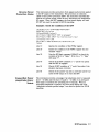
007
E n t e r e d v a l u e o u t o f range
This message is displayed when a value is entered that
does not set the RF output signal within the instrument’s
allowable range. Refer to “Function” in Chapter lb,
“Operation Reference, ” for information on the instrument’s
allowable ranges.
008
Amplitude exceeds s p e c i f i e d range
This message is displayed when the instrument’s amplitude
is set to a level that exceeds + 10 dBm.
010
End of knob range
This message is displayed when the knob is turned but
changing the selected digit would set the instrument to a
value that is not within its allowable range.
lc.2
Operation Messages
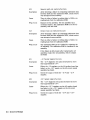
011
Amplitudeexceeds A T T N H O L D l i m i t s
This message is displayed when [-HOLD)
is on and the
amplitude is set to a level that exceeds the vernier range
limits by greater than 5 dBm. Exceeding the 10 dB vernier
range of an attenuator hold setting causes the output level
accuracy to degrade. For information about the vernier
ranges and limits, refer to “Atten Hold” in Chapter lb,
“Operation Reference. ”
012
No e x t e r n a l d c coupling f o r AM
This message is dimlaved when AM is selected and
DC) is also selected. DC coupling
of an external source is not possible for AM. If you press
kHz + EXT DC) YOU will actually get 1 kHz and external UC.
Or, select CEXT) coupling for AM. Additional internal plus
external modulation capabilities (such as 1 kHz + EXT AC)
are available through HP-IB control of the instrument; refer
to Chapter 2, “HP-IB Programming.”
~EXTDC)
or-ci kHz +*EX+
013
AMunspecifiedabove4dBm
This message is displayed when AM is selected and
amplitude is set to greater than 4 dBm. To insure that AM
will meet its specified performance, reduce the amplitude
setting to 4 dBm or less.
014
AMunspecifiedatorbelow1.5MHz
This is caused when AM is selected and RF frequency is set
to 1.5 MHz or less. To insure that AM will meet its specified
performance, increase the RF frequency setting.
015
Help messages o f f
This message is displayed when the instrument is powered
up and the rear panel help switch has been set to disable
the following error messages: 001 , 002, 004 , 005 , 006 ,
007, 008, 010, 011, 012, 013, 014. The second switch
position (next to the timebase adjust, labeled “NOT USED”)
controls the display of these messages.
020
Press
lsAVl t o copy memory FROM 8647/8
This message is displayed when the (
I
J
keyJ
is pressed on an
HP 83301A Memory Interface connected to the instrument.
key to copy the memory registers saved in
Press the
the instrument into the memory interface.
02 1
Copyingregistersfrom8647/8
This message is displayed while the memory registers are
being copied from the instrument to the HP 83301A Memory
Interface.
022
Press(SAV)to copymemory TO 8647/8
This message is displayed when the
key is pressed on an
HP 83301A Memory Interface connected to the instrument.
Press the
key to copy memory registers that had been
saved in the memory interface into the instrument.
Operation Messages
le-3
023
C o p y i n g r e g i s t e r s t o 8647/8
This message is displayed while the memory registers are
being copied from the HP 83301A Memory Interface to the
instrument.
024
I n v a l i d data i n Memory I n t e r f a c e
This message is displayed when the instrument detects that
the HP 83301A Memory Interface does not contain valid
memory register data. Try copying a memory register into
the memory interface first, then initiate a copy from the
memory interface to the instrument again.
025
Communication f a i l u r e : copy aborted
This message is displayed when the instrument is not able to
successfully copy memory registers between the instrument
and the HP 83301A Memory Interface. This message will
be displayed if the cable connecting the instrument to the
primary interface is disconnected during the copy process.
026
Memorycopywas s u c c e s s f u l
This message is displayed when the instrument has
successfully copied the memory registers between the
instrument and the HP 83301A Memory Interface. When
this message is displayed, the copy process is complete
and you can disconnect the memory interface from the
instrument.
Ic.4
Operation Messages
HP-IB - Command
Errors
-101
Invalidcharacter
A syntactic element contains a character which is invalid
for that type; for example, a header containing an
ampersand, SETUP&. This error might be used in place of
errors -121, -141, and perhaps some others.
-102
Syntax e r r o r
An unrecognized command or data type was encountered.
For example, a string was received when the device does
not accept strings. Additional information is available over
HP-IB.
-103
Invalid separator
The parser was expecting a separator and encountered an
illegal character. For example, the semicolon was omitted
after a program unit, 'EMCl:CHl:VOLTS5.
-104
Data t y p e e r r o r
The parser recognized a data element different than one
allowed. For example, numeric or string data was expected
but block data was encountered.
-105
GET not allowed
A Group Execute Trigger was received within a program
message (see IEEE 488.2.7.7).
-108
Parameter not allowed
More parameters were received than expected for the
header. For example, the *EMC common command only
accepts one parameter, so receiving *EMCO,l is not allowed.
-109
Missing parameter
Fewer parameters were received than required for the
header. For example, the *EMC common command requires
one parameter, so receiving *EMC is not allowed.
-111
Header s e p a r a t o r e r r o r
A character which is not a legal header separator was
encountered while parsing the header. For example, no
white space followed the header, thus *GMC"MACRO" is in
error.
-112
Programmnemonictoo long
The header contains more than twelve characters (see IEEE
488.2 7.6.1.4.1).
-113
Undefinedheader
The header is syntactically correct, but it is undefined for
this specific device. For example, *XYZ is not defined for
any device.
Operation Messages
lc-5
-121
I n v a l i d c h a r a c t e r i n number
An invalid character for the data type being parsed was
encountered. For example, an alpha in a decimal numeric or
a “9” in octal data.
-123
Exponent t o o l a r g e
The magnitude of the exponent was larger than 32000 (see
IEEE 488.2,7.7.2.4.1).
-124
Too many d i g i t s
The mantissa of a decimal numeric data element contained
more than 255 digits excluding leader zeros (see IEEE 488.2
7.7.2.4.1).
-128
Numeric d a t a not allowed
A legal numeric data element was received, but the device
does not accept one in this position for the header.
-131
Invalid suffix
The suffix does not follow the syntax described in IEEE
488.27.7.3.2,
or the suffix is inappropriate for this device.
-134
S u f f i x t o o long
The suffix contained more than 12 characters (see IEEE
488.2,7.7.3.4).
-141
I n v a l i d c h a r a c t e r data
Either the character data element contains an invalid
character or the particular element received is not valid for
the header.
- 144
Character d a t a too long
The character data element contains more than twelve
characters (see IEEE 488.2 7.7.1.4).
-148
Character data not allowed
A legal character data element was encountered where
prohibited by the device.
-158
S t r i n g d a t a not allowed
A string data element was encountered but was not allowed
by the device at this point in parsing.
-168
Block data n o t allowed
A legal block data element was encountered but was not
allowed by the device at this point in parsing.
-178
Expression d a t a not allowed
A legal expression data was encountered but was not
allowed by the device at this point in parsing.
1c-6
Operation Messages
HP-IB Execution
Errors
-22 1
Settings conflict
Indicates that a legal program data element was parsed but
could not be executed due to the current device state (see
IEEE488.2 6.4.5.3 and 11.5.1.1.5).
-222
Data out of range
Indicates that a legal program data element was parsed but
could not be executed because the interpreted value was
outside the legal range as defined by the device (see IEEE
488.2, 11.5.1.1.5).
HP-IB
Device-Specific
Errors
-330
Self -test failed
-350
Queue overflow
A specific code entered into the queue in lieu of the code
that caused the error. This code indicates that there is
no room in the queue and an error occurred but was not
recorded.
HP-IB Query
Errors
-410
Query INTERRUPTED
Indicates that a condition causing an INTERRUPTED Query
error occurred (see IEEE 488.2, 6.3.2.3).For example, a
query followed by DAB or GET before a response was
completely sent.
-420
Query UNTERMINATED
Indicates that a condition causing an UNTERMINATED
Query error occurred (see IEEE 488.2, 6.3.2.2).For example,
the device was addressed to talk and an incomplete
program message was received.
-430
Query DEADLOCKED
Indicates that a condition causing a DEADLOCKED Query
error occurred (see IEEE 488.2, 6.3.1.7).For example, both
input buffer and output buffer are full and the device
cannot continue.
-440
query UNTERMINATED after indefinite response
Indicates that a query was received in the same program
message after an query requesting an indefinite response
was executed (see IEEE 488.2 6.5.7.5).
Five secondself test . . .
This message appears when the command *tst? is sent to
the instrument over the HP-IB bus. The instrument runs a
Operation Messages
lc-7
subset of its power-up tests when this message is displayed.
The local key is disabled during this time.
Service Messages
IC-8 Operation Messages
Messages numbered 500 and above relate to the service self
tests provided within the instrument. For information about
troubleshooting the instrument, refer to Chapter 5, “Service.”
2
HP-IB Programming
Background
This signal generator adheres to the IEEE 488.1-1987, IEEE
488.2-1987 and SCPI Version 1992.0 command language.
In 1987, the IEEE released IEEE 488.2-1987, Codes, Formats,
Protocols and Common Commands for Use with IEEE 488.1-1987.
This standard defined the roles of instruments and controllers in a
measurement system and a structured scheme for communication.
In particular, IEEE 488.2 described how to send commands to
instruments and how to send responses to controllers. It defined
some frequently used housekeeping commands explicitly, but each
instrument manufacturer was left with the task of naming any other
types of commands and defining their effect. IEEE 488.2 specified
how certain types of features should be implemented if they were
included in an instrument. It generally did not specify which features
or commands should be implemented for a particular instrument.
Thus, it was possible that two similar instruments could each conform
to IEEE 488.2, yet they could have an entirely different command set.
Standard Commands for Programmable Instruments (SCPI) is the new
instrument command language for controlling instruments that goes
beyond IEEE 488.2 to address a wide variety of instrument functions
in a standard manner. SCPI promotes consistency, from the remote
programming standpoint, between instruments of the same class, and
between instruments with the same functional capability.
HP-IB Programming
2-1
Programming
Guidelines
HP-IB Definition
What is Programmable
HP-IB Address
HP-IB stands for Hewlett-Packard Interface BUS,and is often referred
to as the bus. It is Hewlett-Packard’s implementation of the IEEE
488.1-1987 and the IEEE 488.2-1987 Standard Digital Interface for
Programmable Instrumentation.
All functions are programmable except the front panel power key,
knobs, memory keys, increment set key, arrow keys, frequency
reference keys and the rear panel display contrast control.
The HP-IB Address for the signal generator is preset to 19. I t may be
and the
changed to any address between 00 and 30, by pressing
desired two-digit number.
Error Messages
The HP-IB programming error messages are described in Chapter IC,
“Operation Messages. ”
Programming
Language
Although many system controllers and programming software
languages are compatible with this instrument, all examples and
references in this manual assume the use of an HP controller utilizing
the HP BASIC programming language.
Most instrument settings may be queried via HP-IB. The data returned
from the query will vary from a yes/no (1/0) to the actual setting,
depending on the function. See Table 2-1.
Advanced
Programming
For the majority of applications, remotely programming the signal
generator requires only basic programming knowledge and the
command statements listed later in this chapter. Developing
programs for querying the instrument’s status is considered to be
an advanced application (see “HP-IB Status Reporting. ”) For more
information on HP-IB programming see the Tutorial Description of the
Hewktt-Ftzckard Interfuce Bus (HP Part number 5952-0156).
HP-IB Programming 2-3
Programming
Examples
Note
Programming RF
Frequency
Programming RF
Frequency and FM
Modulation
Examples are provided here to help you understand the required
programming structure. All examples use the HP BASIC programming
language. See Table 2-1 for a complete listing of commands.
Command statements may be concatenated on the same line if
separated by a semicolon. A colon must precede successive command
statements to ensure command hierarchy.
OUTPUT
The output statement (HP BASIC) tells the system
controller to output what follows.
7
The Input/Output select code of the system controller
is 7.
19
The HP-IB address of the signal generator is 19.
Semicolon (;)
A semicolon separates the HP BASIC command from
the output string that follows.
Quotes (" ")
All command statements must be contained in quotes.
FREQ:CW
This command programs the RF frequency. FREQ
must be in the statement first representing its
hierarchy over :CW. The colon (:) is used to separate
the command hierarchy. The signal generator will be
programmed to a RF frequency of 500 MHz.
lIlI-ITPI_IT 71'3; "FREI;!: I:Lij 588 MHZ; :FP1: DE'd 3 K H Z j :FP1:SIIII-IR
E],::T j :FP1: E::.(T: I~l~lIJp
HI: i :HH: !;THT IZIFFj :F'N: STHT OFF j :FPI :STHT
1
1
11.1' I
FM: DEV
This command programs the FM deviation. FM is
higher than DEV in the command hierarchy and is
separated by a colon (:). The signal generator will
be programmed to 3 kHz of deviation.
Semicolon (;)
A semicolon separates completed command
statements.
FM:SOUR:EXT
This command selects the external path for the
modulation source.
FM:EXT:COUP AC This command selects ac coupling.
FM:STAT ON
2-4 HP-IB Programming
This command changes the FM modulation to an
on state. A modulation format must be turned
on before it is active. The other two modulation
formats must be turned off prior to activating the
desired modulation (AM:STAT OFF and PM:STAT
OFF).
Programing RF
Amp1itude
Line 100
This command outputs a query for the RF frequency
setting. You may attach a question mark (?) to any of
the signal generators' commands to query its setting.
Line 200
This command enters the queried frequency setting
into the variable Freq-set.
Line 300
This command prints the queried frequency setting.
OI-ITF'I-IT 719; "POW: HMPL -47 DE:M; :OUTP: STHT
P0W:AMPL
i:it4J"
This command programs the RF amplitude. POW is
higher than AMPL in the command hierarchy and
is separated by a colon. The signal generator's RF
amplitude will be programmed to -47 dBm.
0UTP:STAT ON This command changes the RF amplitude to an on
state. The RF amplitude defaults to an off state when
the instrument is powered on.
HP-I8 Programming 2-5
mble 2-1. Programming Command Statements and Descriptions
0UTP:STAT ON
0UTP:SIIAT OFF
P0W:AMPL <value> <units>
P0W:ATT:AUTO ON
P0W:ATI':AUTO OFF
P0W:REF <value> <units>
P0W:REF:STAT ON
P0W:REF:STAT OFF
FREQ:CW <value> <units>
Modulation
Amplitude Modulation
AM:DEPT <value> PCT
AM:STAT ON
AM:STAT OFF
AM:SOUR INT
AM:SOUR EXT
AM:SOUR INT,EXT
AM:INT:FREQ 1 KHZ
AM:INT:FREQ 400 HZ
AM:EXT:COUP DC
AM:EXT:COUP AC
Frequency Modulation
CAL:DCFM
FM:DEV <value> KHZ
FM:STAT ON
FM:STAT OFF
FM:SOUR INT
FM:SOUR EXT
FM:SOUR INT,EXT
FM:INT:FREQ 1 KHZ
FM:INT:FREQ 400 HZ
FM:EXT:COUP DC
FM:EXT:COUP AC
2-6 HP-IB Programming
Turns the RF output on.
Turns the RF output off.
Sets the amplitude of the RF output t o the desired
<value> and <units>. <value> may be up to 4 digits
plus a sign if applicable, e.g. -127.1 or maximum
resolution of .1 dB, .001 mV, .01 pV. <units> may be
DBM, MV, UV, MVEMF, UVEMF, DBUV, DBUVEMF. If in
reference mode only DB or DBM are allowed.
Turns automatic attenuator control on (this is normally
on).
Turns automatic attenuator control off and holds
present attenuator setting.
Sets a reference to the <value> in <units> as
described in setting amplitude. Reference state must be
on, to be active.
Sets reference to on, making all amplitude changes
relative to the reference.
Sets reference to off,making all amplitude changes
absolute.
Sets the RF frequency to the <value> and <units>.
<value> may be up to 9 digits with a maximum of 10
Hz resolution. <units> may be MHZ, KHZ or HZ.
OUTP:STAT?
POW :AMPL?
POW:ATT:AUTO?
POW:REF?
POW:REF:SIIAT?
FREQ:CW?
~~
Sets AM depth in %, <value> from .1 to 99.9
Sets AM on, FM and PM must have state off.
Sets AM off.
Selects internal source.
Selects external source.
Selects internal and external sources
Selects internal 1 kHz frequency.
Selects internal 400 Hz frequency.
AM cannot be dc-coupled (SCPI allows command).
Selects external ac-coupling for AM.
Eliminates dc FM offset.
Sets FM deviation in kHz, <value> from 0.00 to 9.99
and 10.0 to 99.9, <value> may also be entered in Hz
(HZ).
Sets FM on, AM and PM must have state off.
Sets FM off.
Selects internal source for FM.
Selects external source for FM.
Selects internal and external source.
Selects internal 1 kHz frequency.
Selects internal 400 Hz frequency.
Selects external dc coupling for FM.
Selects external ac coupling for FM.
AM:DEPT?
AM:STAT?
AM:SOUR?
AM:INT:FREQ?
AM:EXT:COUP?
FM:DEV?
FM:STAT?
FM:SOUR?
FM:INT:FREQ?
FM:EXT:COUP?
mble 2-1. Programming Command Statements and Descriptions (continued)
~
Command Statement
Description
Query
Modulation (continued)
Phase Modulation
PM:DEV <value> RAD
P M : m T ON
P M : m T OFF
PM:SOUR INT
PM:SOUR EXT
PM:SOUR INT,EXT
PM:INT:FREQ 1 KHZ
PM:INT:FREQ 400 HZ
PM:EXT:COUP DC
PM:EXT:COUP AC
Set phase modulation in radians (RAD), <value> from
0.00 to 9.99 and 10.0
Sets PM on. AM and FM must have state off.
Sets PM off.
Selects internal source for PM.
Selects external source for PM.
Selects internal and external source.
Selects internal 1 kHz frequency.
Selects internal 400 Hz frequency.
Selects external dc coupling for PM.
Selects external ac coupling for PM.
Standard Commands for Status
&e HP-IB Status &porting examples
SWT:QUES:POW:ENAB<NRl>
SWT:QUES:MOD:ENAB<NR1>
*RST
WAI
'CLS
'ESE <dec. n u n . data>
'OPC
*SRE <dec. mum. data>
Returns contents of the power condition register.
Enables <NR1> event registers for power.
Returns contents of enabled event registers for power.
Returns contents of the modulation condition register
Enables <NR1> event registers for modulation.
Returns contents of enabled registers for modulation.
Resets the signal generator to a default state (see SCPI
Command Reference).
Returns the instrument's identity.
Executes an instrument self-test.
Instrument waits until previous commands are
completed.
Clears status and event registers.
Enables Standard Event Status Register bits.
Queries the Standard Event Status Enable Register.
Queries the Standard event Status Register.
Enables the Operation Complete bit of the Standard
Event Status Register.
Queries the Operation Complete bit of the Standard
Event Register.
Enables the bits in the Status Byte that will cause a
Service Request.
Queries the Service Request Enable Register.
Queries the Status Byte with the MSS bit.
PM:DEV?
PM:STAT?
PM:SOUR?
PM:INT:FREQ?
PM:EXT:COUP?
SIXT:QUES:POW:COND?
SIIAT:QUES:POW:EVEN?
SWT:QUES:MOD:COND?
SIXT:QUES:MOD:EVEN?
*IDN?
*TSr?
*ESE?
*ESR?
*OPC?
* SRE?
* STB?
HP-IB Programming
2.7
HP-IB Status
Reporting
The IEEE 488.2 standard provides a status byte for instrument status
reporting. This status byte may be accessed by using IEEE 488.2
Common Commands and SCPI Status Commands. The following figure
shows the status reporting structure for instrument operation.
The following examples will be used to explain instrument operation
status.
rn External Modulation Input Status
rn
Reverse Power Protection Status
rn Unspecified Power (Amplitude) Entry Status
General IEEE 488.2 status reporting will not be covered. The above
operating status will satisfy most needs for status reporting.
POWer Status Register
NOTE:
Unmarked tits in registers do not
apply for normal operationst~tus.
These blts mclrt be masked when
querying status.See me
programming examples.
Reverse Power
UnspecitledAmplitude
Ext. Mod. Level Hlgh
Ext Mod. Level Low
Unspecified
Devlce Dependent E m
Execdon E m
Comnand Error
status.dnv
Figure 2-1. HP 8647A Status Register Model
2-8 HP-IB Programming
External Modulation
Input Level Status
External modulation input level status may be queried for high, low
or input level correct. The instrument automatically detects the input
level (1 Vpk into 600 ohms for full scale modulation) and displays
the result on the front panel display but must be queried for HP-IB
reporting.
Example: Check the Condition of Modulation Input (High or
Low)
18 OUTPUT 71’3;“STHT: QUES: MEID: tZtItt.iD?”
Et.jTER 719; $'slue
tli:i!j=B It.jHt.IL1
1IJE. 1
I F Mod=l THEN PRIt4T “ E x t . M c l d . Input. H i & I ”
rloid=B It.IHt.ID I::’O).~
1IJe 9 2 )
Eu8 IF tlolj=2 THEt.4 F‘FIItJT ”E;.:t.. MI:I!~. Input. LI:zI.,.I”
78 Et.jK1
28
38
48
58
Line 10
Queries the condition of the MODulation register.
Besides querying the condition you may also query
if an event has occurred, such as the external
modulation input being high or low at some previous
time. Replace the COND? with EVEN? to read the
event status. Reading the event status clears the
register.
Line 20
Enters the condition of the MODulation register into
the variable “Value”.
Line 30
Uses the HP Basic command, BINAND to check the
contents of bit 0 in “Value”. If bit 0 is a “ 1 ” it will be
reported as a decimal equivalent “1” and “Mod” will
equal “ 1 ”.
Line 40
Checks if the MODulation condition is 1 ” and if true,
prints that the external modulation input is high.
Line 50
Uses the HP Basic command, BINAND to check
the contents of bit 1 in “Value”. If bit 1 (decimal
equivalent “2”) is a “ l ” ,“Mod” will equal “1”.
Line 60
Checks if the MODulation condition is “2” and if true,
prints that the external modulation input is low.
‘I
HP-IB Programming
2-9
Example: Generate a Service Request for External
Modulation Input (High or Low)
18 I:IIJTPI-IT 71'3; ":STHT: QIJES: tKC1: Et433 3"
20 IIII-ITF'I-IT 71'3; "STFIT: QIJES: EHHB 12:8"
:38iIil-lTPl)T 714; ll+:;RE ::;I1
48 IF SPIIlLL ( 7 1'3:I THE14 FFF:1t.IT I I E x t . t$:ld.
1rlpijt. H i qh. . . ' L ~ J
Cl&. PlZt. elj
58 IIILlTPlJT 71'3; "+lI:LS"
ceJ8Et.jD
.
2-10
HP-IB Programming
Line 10
Enables bits 0 and 1 (decimal equivalent 3) in the
MODulation register. Enabling these bits masks other
bits in the MODulation register from reporting their
status in the summary bit to QUEStionable.
Line 20
Enables bit 7 (decimal equivalent 128) in the
QUEStionable register. Enabling this bit masks other
bits in the QUEStionable register from reporting their
status in the summary bit to STATUS.
Line 30
Enables bit 3 (decimal equivalent 8) of the STATUS
register. Enabling this bit masks other bits from
reporting.
Line 40
Uses the HP Basic command, SPOLL, (Serial Poll)
to see if the service request bit is reporting any
interrupts.
Line 50
Clears all status registers. Clearing the status registers
is not absolutely necessary, but is used here because
of the unknown state of the instrument.
Reverse Power
Protection Status
This instrument provides protection from signals inadvertently applied
to the RF output of the instrument. This protection is commonly
called reverse power protection (RPP). The instrument automatically
detects the reverse power, which in turn, disconnects the instruments
RF output. When the RPP engages, the front panel display will read
RF OFF but must be queried for HP-IB reporting.
Example: Check the condition of the RPP
18 IIIIJTFI-IT 719; "!zTHT: G!I-IE:S: PCtW: ~ ~ C l ~ j [ : l ' ? ' "
28 EEjTEE 7 13 j $'a 1I J ~
;:a F:pp=B 1t.jHbj[>('u'a1IJe 3 1
48 I F R F p = 1 THEN FF:INT "WF is e r i ~ ~ a ~ 3 e d "
58 1F Rpp= 1 THEN 1t.jPlJT 15 t-ea.>et-se poi.,jet- i npijt.
::I
1:l:It-rel~t. e l j ( 'r',+l
a; 'I 9 H$
688 I F H$="'f"THEt.j IIlIJTPI-IT71'~; "IIIlJTF': !STHT
-i'd- -.t N L.-3
Line 10
Queries the condition of the POWer register.
Line 20
Enters the condition of the POWer register into the
variable "Value".
Line 30
Uses the HP Basic command, BINAND to check the
contents of bit 0 in "Value". If bit 0 is a "l","Rpp"
will equal 1 ,
"
Unspecified Power
(Amplitude) Entry
Status
I:It.j"
"
Line 40
Checks if the RPP condition is "1" and if true prints
that the RPP is engaged.
Line 50
Checks if RPP condition is 1' and if true asks if the
situation has been corrected.
Line 60
Checks if the answer was yes to correction and if true
turns the RF output on to reset the RPP.
This instrument provides a message if an amplitude entry is requested
above + 10 dBm and less than or equal to + 13 dBm or an attenuator
hold range is exceeded (see operating part of manual). When an
unspecified amplitude is entered, the front panel display will read
"Amplitude exceeds specified range, " but must be queried for HP-IB
reporting.
HP-IB Programming
2-1 1
Example: Check the Condition of Unspecified Power Entry
10 I:IIATF'IlT 71'3; "STHT: IS!I-IES: FOW: I~OHD?"
18 Et.jTER 71'3:'t).al1~e
::a F'l:lI,.I-spelz=B It.jHt.jD 1: Ini'a 1IJe3 2 :I
4 8 I F FI:II.,,I-~~~I:=~ THE14 PRIbjT "Mmpl it.ude iunspecif ied"
58 Et.j[:l
2-12 HP-IB Programming
Line 10
Queries the condition of the POWer register. Besides
querying the condition you may also query if an
event has occurred. Replace the COND? with EVEN?
to read the event status. Reading the event status
clears the register.
Line 20
Enters the condition of the POWer register into the
variable "Value".
Line 30
Uses the HP Basic command, BINAND to check
the contents of bit 1 in "Value". If bit 1 is "high",
Pow-spec will equal "2".
Line 40
Checks if Pow-spec equals 2 and then prints that the
amplitude is in an unspecified range.
HP 8647A SCPI
Command
Reference
Wble 2-2. Dictionary of Terms
Terms
DescriDtion
<NRf>
Indicates an ASCII representation of a number if required
in the command statement. The number may be an integer
or floating-point, and may include a decimal exponent. (nrf
stands for “flexible numeric representation”. For further
information, refer to the IEEE 488.2 standard.)
<NRl>
Indicates an ASCII representation of a number if required
in the command statement. The number must be an integer
and may not include decimal points. For further
information, refer to the IEEE 488.2 standard.)
<AM term>
Indicates that a “PCT” termination is required in the
command statement. If no termination is specified, a “PCT”
value is assumed.
<freq term>
Indicates that a “HZ”, ”KHZ”, “GHZ”, or “MHZ”
termination is required in the command statement. IF the
command is not terminated then “HZ” is assumed.
~
~~
~~
<angle term>
Indicates that a “RAD” termination is required in the
command statement. If no termination is specified then
“RAD” is assumed.
<amp1 term>
Indicates that a “DB”, “DBM”, “DBUV”, “UV”, “MV”, “ V ” ,
“UVEMF”, “MVEMF”, or “DBUVEMF” termination is
required in the command statement. If no termination is
specified then “DBM” is assumed.
[command]
Bracketed commands are optional. SCPI assumes the
optional command is present.
Parameters separated by
is acceptable.
“1” indicates that either parameter
Parameters separated by
parameters are allowed.
“, indicates that multiple
”
HP-IB Programming 2-13
AM Subsystem
CSOURcel
:AM
[ :DEPTh] ?
[:DEPTh]
<NRf> [<AM term>]
Sets AM depth in percent. *RST value is 30%.
:STATe?
:STATe
ON I OFF
I 1I
0
Turns AM modulation ON or OFF. AM is not turned on by just setting
AM:DEPTh. Turning AM modulation ON will not automatically turn
OFF any other types of modulation. Turning any or all modulation
types ON or OFF must be done explicitly. If a modulation type is
turned ON while another modulation type is ON, an execution error
-221 is generated, and the state of the instrument is unchanged. *RST
value is OFF.
:SOURce?
:SOURce
INTernal I EXTernal [,INTernal 1,EXTernalI
Selects AM source. 'RST value is INTernal.
:EXTernal
:COUPling?
:COUPling
AC I DC
Sets source coupling for AM. The GROund parameter defined by the
1991 SCPI Command Reference (17.1.9.2) is not supported. *RST
value is DC.
: INTernal
:FREQuency?
:FREQuency
<NRf > [<freq term>]
Sets the frequency of the AM internal signal source. Legal values are
400 Hz and 1 kHz. *RST value is 1 kHz.
CAL Subsystem
[SOURcel
:CAL
:DCFM
Eliminates the offset in dc FM so that the carrier frequency remains
the same with no modulation applied. External dc modulation
must be on to implement this calibration or execution error -221 is
generated.
2.14
HP-IB Programming
F M Subsystem
[SOURcel
:FM
[ :DEViat ion] ?
[ :DEViat ion]
<NRf > [<freq term>]
Sets FM deviation. *RST value is 3 kHz.
:STATe?
:STATe
ON I OFF I 1 I 0
Turns FM modulation ON or OFF. FM is not turned on by just setting
FM:DEViation. Turning FM modulation ON will not automatically turn
OFF any other types of modulation. Turning any or all modulation
types ON or OFF must be done explicitly. If a modulation type is
turned ON while another modulation type is ON, an execution error
-221 is generated, and the state of the instrument is unchanged.
*RST value is OFF'.
:SOURce?
:SOURce
INTernal 1 EXTernal [,INTernal I ,EXTernall
Selects FM source. *RST value is INTernal.
:EXTernal
:COUPling?
:COUPling
AC I DC
Sets source coupling for FM. The GROund parameter defined by the
1991 SCPI Command Reference (17.4.9.2) is not supported. *RST
value is DC.
:INTernal
:FREQuency?
:FREQuency
<NRf> [<freq term>]
Sets the frequency of the FM internal signal source. Legal values are
400 Hz and 1 kHz. *RST value is 1 kHz.
HP-IB Programming
2-15
Subsystem
:FREQuency
C:CW I :FIXedl?
[:CW I :FIXedl
C N R f > [<freq term>]
This function selects a frequency for the continuous wave non-swept
signal. *RST value is 100 MHz.
OUTPut Subsystem
Omput
:STATe?
:STATe ON I OFF I 1 I 0
This function controls the state of the RF output. When
0UTPut:STATe is OFF, the RF source level is set to off. Turning
0UTPut:STATe ON causes the programmed CW signal to be present at
the output terminal. *RST value is OFF.
2-16 HP-18 Programming
PM Subsystem
CSOURcel
:PM
[:DEViation]?
[:DEViation]
<NRf> [<angle term>]
Sets PM deviation in radians. *RST value is 1.0 RAD.
:STATe?
:STATe
ON
I
OFF I 1 I 0
Turns PM modulation ON or OFF. PM is not turned on by just setting
PM:DEViation. Turning FM modulation ON will not automatically turn
OFF any other types of modulation. Turning any or all modulation
types ON or OFF must be done explicitly. If a modulation type is
turned ON while another modulation type is ON, an execution error
-221 is generated, and the state of the instrument is changed. *RST
value is OFF.
:SOURce?
:SOURce
INTernal 1 EXTernal [, INTernal I ,EXTernall
Selects PM source. *RST value is INTernal.
:EXTernal
:Cowling?
:COUPling
AC
I DC
Sets source coupling for PM. The GROund parameter defined by the
1991 SCPI Command Reference (17.10.9.2) is not supported. *RST
value is DC
:INTernal
:FREQuency?
<NRf> [<fr e q term>]
:FREQuency
Sets the frequency of the PM internal signal source. Legal values are
400 Hz and 1 kHz. *RST value is 1 kHz.
HP-IB Programming
2-17
POWer Subsystem
CSOURcel
:POWer
[ :LEVel] [ :IMMediate] [ :AMPLitude] ?
Returns the value of the current CW amplitude. The return value is in
units of DBM if P0Wer:REFerence:STATe is OFF, or it is in DB,relative
to the current value of P0Wer:REFerence if P0Wer:REFerence:STATe
is ON.
[ :LEVel] [ :IMMediate] [ :AMPLitude]
<NRf > [Campl
term>]
Sets CW amplitude. *RST value is -136 dBm.
:ATTenuat ion
:AUTO?
:AUTO
ON
I
OFF I 1 I 0
When set ON, the firmware will control the attenuators. Turning it
OFF causes the attenuator range to hold to it's present setting. 'RST
value is ON
:REFerence?
:REFerence
C N R f > [<amp1 term>]
Sets a reference value which, if STATe is ON, allows all amplitude
parameters to be queriedhet as relative to the reference value. *RST
value is 0 dBm.
:STATe?
:STATe
ON I OFF
I
1 I0
Determines whether amplitude is output in absolute or relative mode.
*RST value is OFF.
2-1 8
HP-IB Programming
STATUSSubsystem
STATUS
: QUEStionable
C :EVENt] ?
Returns the contents of the event register associated with the status
structure.
:CONDit ion?
Returns the contents of the condition register associated with the
status structure. Reading the condition register is nondestructive.
:ENABle
<NRl>
Sets the enable mask which allows true conditions in the event
register to be reported in the summary bit.
:ENABle?
Queries the enable mask.
:POWer
[ :EVENt] ?
:CONDition?
:ENABle
<NR1>
:ENABle?
:MODulat ion
[ :EVENtl ?
:CONDition?
:ENABle
<NRl>
:ENABle?
HP-IB Programming
2-19
SYSTem Subsystem
SYSTem
:ERRor?
Returns any system error message. The format of the response is
<error number>, <error string>.
:VERSion?
Returns a formatted numeric value corresponding to the SCPI version
number for which the instrument complies. The format of the
response is YYYYV. The Ys represent the year version (for example,
1990) and the V represents an approved revision number for that
year.
2.20 HP-IB Programming
HP-IB Capabilities
The instrument is designed to be compatible with a controller that
interfaces in terms of the bus codes summarized in the table. This
table describes each of the interface functions that are available with
this instrument as defined by the IEEE 488.2-1987
Capability
Source Handshake
Comment
Code
SH1
Full Capability
Acceptor Handshake AH1
Full Capability
mker
T6, TEO Basic Talker, Serial Poll, untalk on MLA
Listener
L4,LEO Basic Listener, unlisten on MTA
Service Request
SR 1
Full Capability
Remote Local
RL1
Full Capability
Parallel Poll
PPO
No Capability
~
Device Clear
Device Trigger
Controller
Electrical Interface
~~
~
~
I DC1 I Full Capability
I DTO 1 No Capability
1 CO
I E2
1 No Capability
I Tristate (1MB/sec Max)
HP-IB Programming
2-21
HP-IB Connector
Information
Hewlett-Packard Interface Bus
0
Signal Ground
P/O Twisted Pair With 11
Pi0 Twisted Pair With 10
P/O Twisted Pair With 9
P/O Twisted Pair With 8
P/O Twisted Pair Witt, 7
PI0 Twisted Pair With 6
Should be grounded
near termination of
other wire of twiated
pair
Shield, Connect to earth ground
ATN
SRQ
IFC
NDAC
NRFD
DAV
EO1
D104
D103
REN
D108
D107
D106
Dl05
Isometric
Thread M3.5x 0.6
D102
0101
-b0
24 Pin MicreRibbon
(Series 57) Connector
The Hewlelt-Packard Interface Bus logic levels are l l L compatible, that is, the true (1) state is 0.0 Vdc to +0.4Vdc and the
false state (0) is +2.5Vdc to +5Vdc.
HP 1251-0293; Amphenol 57-30240
HP 10833A4,1 meter (3.3 ft.)
HP 108033B,2 meters (6.8ft.)
HP 10833C, 4 meters (13.2 ft.)
HP 108330, 0.5 meters (1.6 ft.)
1. A Hewiett-PackardInterface Bus system may contain no more than 2 meters (6.6 lt.) of connecting cable per instrument.
2. The maximum accumlative length of connecting cable for any Hewett-Packard Interface Bus system is 20 meters (65.5 ft.).
n:banuals\boilervlpibcon 1.dw
2-22 HP-IB Programming
3
Installation
Unpacking Your
Signal Generator
1. Unpack the contents of the shipping container.
2. Inspect the shipping container for damage.
If the shipping container is damaged or the cushioning material
inside is stressed, keep them until you have checked the
instrument for proper operation.
3. Inspect the signal generator to ensure that it was not damaged
during shipment.
If mechanical damage or defects have occurred, notify the carrier
as well as the Hewlett-Packard ofice. Keep the shipping materials
for inspection by the carrier.
~~
Warning
To avoid hazardous electrical shock, do not connect AC power to
the instrument when there are any signs of shipping damage to
any portion of the outer enclosure (cover and panels).
Caution
Ventilation Requirements: When installing the instrument in a
cabinet, the convection into and out of the instrument must not be
restricted. The ambient temperature (outside the cabinet) must be
less than the maximum operating temperature of the instrument
by 4 "C for every 100 watts dissipated in the cabinet. If the total
power dissipated in the cabinet is greater than 800 watts, then forced
convection must be used.
Connecting AC
Power
Warning
This is a Safety Class I product (provided with a protective
earthing ground incorporated in the power cord). The mains
plug shall only be inserted in a socket outlet provided with a
protective earth contact. Any interruption of the protective
conductor, inside or outside the instrument, is likely to make the
instrument dangerous. Intentional interruption is prohibited.
If this instrument is to be energized via an external
autotransformer f o r voltage reduction, make sure that its
common terminal is connected to a neutral (earthed pole) of the
power supply.
This instrument is equipped with a three-wire power cable. When
connected to an appropriate ac power receptacle, this cable grounds
Installation
3-1
the instrument cabinet. The type of Mains plug shipped with each
instrument depends on the country of destination. Refer to Figure 3-2
for the part numbers of the power cables and mains plugs available.
Power Requirements
The signal generator requires a power source of either 50/60/400 Hz
at 100/120 V or 50/60 Hz at 200/240 V. The voltage ranges for these
nominal voltage values are shown in Bble 3-1. Power consumption is
150 VA maximum.
"hble 3-1.Voltage Ranges for Nominal Voltage Values
I Available ac Voltage 1
Voltage Range
I
90 to 110 V rms
108 to 132 V rms
198 to 242 V rms
216 to 250 V rms
Caution
Replacing the Fuse
This instrument has autoranging line voltage input; be sure the supply
voltage is within the specified range.
If a fuse failure is suspected, replace the 250 V, 3A, type F fuse (HP
part number 2110-0780) as follows:
1. Unplug the power cord from the line module.
2. Use a flat-bladed screw driver to pry and unseat the fuse housing
from the line module.
3. Remove the cartridge and inspect the fuse positioned toward the
front of the instrument.
3-2 Installation
.... ....
0 0.0
000
Figure 3-1.Replacing the Fuse
Installation 3-3
PLUG TYPE
**
CABLE
PLUG
DESCRIPTION
CABLE
HP PART
FOR USE
I N COUNTRY
M i n t Gray
M i n t Gray
Great B r i t a i n ,
CM (INCHES)
NUMBER
250V
CABLE
COLOR
LENGTH
8 120-1 351
S t r a i g h t*
8120-1703
9 oo
BS1363A
229 ( 9 0 )
229 (90)
Cyprus, Nigeria,
Singapore,
Z irnbabwe
250V
250V
8 120- 1369
Straight*
8 120-0696
9 oo
* CEE7-Y11
8 1 20-1689
Straight
8 1 20- 1 6 9 2
9 oo
125V
8120-1348
Straight*
fi
8 1 20-1 5 3 8
goo
8 1 20-1 3 7 8
St r a i gh t
8 120-4753
S t r a i gh t
9 o'
9 oo
250V
8 120-1 5 2 1
8 120-4754
8 1 20-5 182
8 120-5 1 8 1
*
**
NZSS198/ASC11:
*
S t r a i gh t*
30
'
NEMA5-15P
NEMA5- 1 5P
201 ( 7 9 )
Gray
221 ( 8 7 )
Gray
201 ( 7 9 )
d i n t Gray
201 ( 7 9 )
M i n t Gray
~
l
B I ack
203 ( 8 0 )
203 ( 8 0 )
203 ( 8 0 )
j a d e troy
230 ( 9 0 )
NEMA5-?
5P
Jade Gray
203 ( 8 0 )
230 ( 9 0 )
Jade Gray
200 ( 7 8 )
200 ( 7 8 )
Jade Gray
Jade Gray
P a r t number f o r p l u g i s i n d u s t r y i d e n t i f i e r f o r p l u g o n l y .
HP P o r t Number f o r c o m p l e t e c a b l e , i n c l u d i n g p l u g .
E = E a r t h Ground;
L = Line;
N = Neutral.
FORMAT80
Figure 3-2. Power Cable and Mains Plug
3.4 Installation
Argentina,
Australia,
New Z e a l o n d ,
Mainland Chino
E a s t a n d West
Europe. Central
African Republic
U n i t e d Arab
Republ i c
(unpolarized in
many nations)
~U n i t e~ d S tka t e s
Canada.
Japan (100 V or
200 v ) , B r a z i 1 ,
Colombia, Mexico
Phi 1 i pp i nes,
Saudi0 Arabia,
Taiwan
Israel
Number s h o w n f o r
cable
is
Turning On the
Signal Generator
If you are operating this instrument in extreme environmental
conditions, refer to the following operation limitations.
The following minimum conditions are required for safe operation of
this instrument:
I
Indoor use
I
Altitude < 4572 meters (15,000 feet)
I
Temperature: 0 " to 50 "C, unless specified differently
w Maximum relative humidity 80% for temperatures up to 31 O
C
decreasing linearly to 50% relative humidity at 40 OC
The instrument performs a diagnostic self test on power-up. If any
problems are detected with functionality it will display a message.
Refer to Chapter IC, "Operation Messages, for further information
about the messages.
"
Caution
This instrument is designed for use in Installation Category I1 and
Pollution Degree 2 per IEC 1010 and 664 respectively.
Connecting to
Other Instruments
Coaxial mating connectors used with the signal generator should be
either 500 BNC or 500 type N male connectors that are compatible
with those specified in UL MIL-C-39012.
Storing the Signal
Generator
The instrument should be stored in a clean, dry environment. The
following environmental limitations apply to both storage and
shipment.
v
Temperature -20 OC to
I Humidity
I Altitude
Note
+ 70 "C
< 95% relative
15,300 meters (50,000 feet)
The cabinet should only be cleaned using a damp cloth.
Installation
3-5
Shipping th.e Signal
Generator
Containers and materials identical to those used in factory packaging
are available through Hewlett-Packard offices. If the instrument
is being returned to Hewlett-Packard for servicing, attach a tag
indicating the type of service required, return address, model number,
and full serial number. Also, mark the container FRAGLLE to assure
careful handling. In any correspondence, refer to the instrument by
model number and full serial number.
If you are using other packaging, follow the guidelines below:
1. Wrap the instrument in heavy paper or plastic.
2. Use a strong shipping container. A double-wall carton made of 2.4
MPa (350 psi) test material is adequate.
3. Use enough shock-absorbing material (75 to 100 millimeter layer;
3 to 4 inches) around all sides of the instrument to provide a firm
cushion and to prevent movement in the container. Protect the
front-panel with cardboard.
4. Seal the shipping container securely.
5 . Mark the shipping container FRAGILE to assure careful handling.
3.6
Installation
Specifications
This chapter contains specifications and supplemental characteristics
for the HP 8647A signal generator.
Specifications describe the instrument’s warranted performance
over the 0 to 50° temperature range and apply after a 30 minute
warm-up unless otherwise noted. All performance below a carrier
frequency of 250 kHz is typical.
1
Supplemental characteristics (shown in italics) are intended to
provide information useful in estimating instrument capability
in your application by describing typical, but non-warranted
performance.
Specifications
4-1
Resolution
Display
1 Hz
10 Hz
Accuracy*
Typically ~ S X ~ x
O carrier
- ~ frequency i n Hz,
f 1 . 5 ~ 1 0 -x~carrier frequency for Option 1M.
Switching Speed
I< 120ms
Internal Reference
Oscillator
Accuracy and stability* (cdibration and adjustment
dependent)
f Aging rate f temperature effects f line voltage effects
Standard
Timebase
High Stability
Timebase Opt. 1E5
< 4Z0.5 ppm/year*
< f 0 . 0 5 ppm
< f O . l ppm
Aging
Temperature
Line Voltaget
< f 2 ppmlyear
< f l pprn
< 4Z0.5 ppm
External reference oscillator input
Accepts 2, 5, 10 MHz &5 ppm and a level range of 0.5 V to
into 50 ohms
2 V,,,
4.2 Specifications
output
IRange
I + 10 to -136
Display Resolution
10.1 dB
Accuracy*
I k1.5 dB
J
dBm
* Accuracy is valid from maximum specified output power to -127 dBm. It's typically f 3 . 0 dB below -127 dBm.
50 watts into 50 ohms
Reverse power protection
SWR (output
< -6
I
I 2.O:l
dBm, typical)
1 Nominally 50 ohms
Output Impedance
Spectral Purity
~~
I < -30 dBc (output 5 + 4 dBm)
~
Harmonics
Nonharmonics (> 5 kHz offset,
5
+ 4 dBm output level)
I < -60
dBc*
* Non-harmonic spurious are -55 dBc from 220 to 250 MHz.
Residual FM (CCIlT,rms)
< 249 MHz
< 501 MHz
5
1OOOMHz
SSB Phase Noise (at 20 kHz ofset, typical)
at f, 500 MHz
at f, 1000 MHz
< 20 Hz, typically < 11 Hz
< 10 Hz, typically < 6 Hz
< 20 Hz,typically < 11 Hz
< -11Od&/HZ
< -106dBC/Hz
Specifications
4-3
Frequency
Modulation
Peak Deviation (rates > 25 Hz ac FM)
< 249 MHz
< 501 MHz
5 1000 MHz
0 to 100 kHz
0 to 50 kHz
0 to 100 kHz
Resolution
5 10% peak deviation
> 10%to maximum peak deviation
10 Hz
100 Hz
Deviation Accuracy (internal 1 kHz rate)
I f7.5% of FM deviation f30 Hz
Rates
Internal
External DC
External AC
400 Hz or 1 kHz
dc to 75 kHz (typical, 3 d B BW)
20 Hz to 75 kHz (typical, 3 d B BW)
Distortion (1 kHz rate, THD
(88 to 108 MHz)
+
N, 0.3to 3 kHz BW)
Carrier frequency accuracy relative to CW in dc FM'
1%at deviations > 4 kHz
(< 0.5% at deviations > 75 kHz)
<
I k500 Hz (typ. 200)at deviations < 10 kHz
* Specifications apply over the 25 k 5 OC range.
FM + FM
4-4 Specifications
Internal 1 kHz or 400 Hz source plus external. In internal
plus external FM mode, the internal source produces the set
level of deviation. The external input should be set to
5 k0.5 Vpk or 0.5 Vdc (one-half of the set deviation).
Peak Deviation Range
< 249 MHz
< 501 MHz
5 1OOOMHz
0 to 10 radians
0 to 5 radians
0 to 10 radians
Resolution
10.01 radian
Deviation Accuracy (internal 1 kHz rate, typical)
f7.5% of deviation setting f0.05radians
Rates
Internal
€Wema1
400 Hz or 1 kHz
20 Hz to 10 kHz (typical, 3 d B BW)
Distortion (1 kHz rate)
< 2%at deviations 2 3 radians
Amplitude
Modulation
AM performance is not specified below 1.5 MHz.
Range
Resolution
IAccuracy (1 kHz rate)
0 to 100%;output 5 4 dBm
10.1%
115%of setting f1.5%
Rates
Internal
Ezternal
400 Hz or 1 kHz
20 Hz to 25 kHz (typical, 3 d B BW)
Distortion (1 kHz rate, THD + Noise, 0.3 to 3 kHz BW)
at 30%AM
at 90%AM
< 2%
< 3%
I
Specifications 4-5
Modulation Source
Internal
External
Interface
Control Languages
Functions Controlled
IEEE-488 Functions
400 Hz or 1 kHz, front panel BNC connector provided at
nominally 1 Vp-p into 600 ohms.
1 Vp into 600 ohms (nominal) required for full scale
modulation. (HigNLow indicator provided for external
signals 5 10 kHz.)
HP-IB (IEEE-488.2-1987) with Listen and ?Blk
SCPI version 1992.0
All front panel functions except power switch and knobs.
SH1, AH1, T6, TEO, L4, LEO, SR1, RL1, PPO, DC1, DTO,
ICO, E2
Environmental
_
Operating temperature range
Shock and vibration
Leakage
_
_
_
_
_
~
~
0 to 50 OC
Meets MIL STD 288003 Type 111, Class 5, Style E
Conducted and radiated interference meets MIL STD 461B
RE02 Part 2 and CISPR11. Lsakage is typically < 1 p V
(nominally 0.1 p V with a 2 turn loop) at 5 1001 AD€..,
when
measured with a resonant dipole ant%nna one inch from
any surface (excwt t h rear panel) with output level < 0
dBm (all inputs/outputs properly terminated).
General
Power Requirements
Internal Diagnostics
Storage Registers
Weight
Dimensions
4-6 Specifications
90 to 264 V; 48 to 440 Hz; 170 VA maximum
Automatically executes on instrument power-up. Assists
user in locating instrument errors and locating faulty
module.
300 storage registers with sequence and register number
displayed. Up to 10 sequences are available with 30
registers each.
7 kg (15 lbs) net; 9 kg (20 lbs) shipping
165H x 330W x 333D mm (6.5H x 13W x 13.2D in.)
Options
1E5
1CM
OB0
OB1
W30
Translated Operating Manuals
Option AB0
Option AB1
Option AB2
Option ABE
Option ABJ
Transit Case
Remote Interface
Memorv Interface
I
High stability timebase
Rack Kit, part number 08647-61020
Delete manual
Extra manual (includes service information)
Chinese for 'pawan, part number 08647-90010
Korean, part number 08647-90011
Chinese for PRC, part number 08647-90012
Spanish, part number 08647-90013
Japanese, part number 08647-90016
Part number 5960-2229
HP 83300A
HP 83301A
Specifications
4-7
Regulatory
Information
IS0 9002 Compliant
The HP 8647A signal generators are manufactured in an IS0 9002
registered facility in concurrence with Hewlett-Packard’s commitment
to quality.
Statement of
Compliance
This instrument has been designed and tested in accordance with
IEC Publication 348, Safety Requirements for Electronic Measuring
Apparatus, and has been supplied in a safe condition. The instruction
documentation contains information and warnings which must be
followed by the user to ensure safe operation and to maintain the
instrument in a safe condition.
Noise Declaration
4.8
Specifications
Notice for Germany: Noise Declaration
LpA < 70 dB
am Arbeitsplatz (operator position)
normaler Betrieb (normal position)
nach DIN 45635 T. 19 (per IS0 7779)
Service
This chapter provides the procedures to troubleshoot your instrument
to the assembly level. In addition to this introductory information
which includes shipping instructions and an overview of the operation
verification software, this chapter consists of the following three
major sections.
Chapter 5a provides the theory of operation for each major
assembly and a simplified block diagram to describe the
instrument’s operation.
w Chapter 5b provides troubleshooting information consisting of a
troubleshooting checklist, fuse replacement instructions, a diagram
of modulation test points and power supply LEDs, a power supply
distribution diagram, and an instrument block diagram.
Chapter 5c lists the service error messages and gives a description
of the error, and possible causes and resolutions.
Warning
These servicing instructions are for use by qualified personnel
only. To avoid electrical shock, do not perform any servicing
unless you are qualified to do so.
Warning
This is a Safety Class 1 Product (provided with a protective
earthing ground incorporated in the power cord.) The mains
plug shall only be inserted in a socket outlet provided with a
protective earth contact. Any interruption of the protective
conductor inside o r outside of the instrument is likely to make
the instrument dangerous. Intentional interruption is prohibited.
Shipping Your
Instrument Back to
Hewlett-Packard
If it becomes necessary to ship your instrument back to HP, use the
original packaging or something comparable that provides sufficient
padding to protect the instrument. (See Chapter 3, “Installation,”for
more detailed packaging information.) Fill out a blue repair tag and
attach it to the instrument. Repair tags are located at the end of this
manual behind the index.
A list of H P sales and service offices is located at the front of this
book on page v.
Service
5-1
Operation
Verification
Software
This software performs a quick automated verification of the
HP 8647A functionality. The software uses the HP 8902A measuring
receiver and HP 11722A power sensor to verify the HP 8647A level
accuracy, modulation accuracy, and dc FM frequency stability.
These tests supply a high degree of confidence that the HP 8647A is
functioning correctly. The software is a subset of the performance
tests that are described in chapter 8. For a complete calibration, all
performance tests and data points described in the performance test
chapter must be verified. Whenever there is any doubt about the
performance of the HP 8647A, the manual performance tests should
be used to resolve the issue.
This software is provided without any warranties or support. It may
be copied or modified so long as it is not reproduced for sale.
The software is a large program with many compiled subroutines. The
software must be run under HP BASIC 6.0 using an HP series 200 or
300 computer. The memory required for the program is approximately
6 MBytes. The HP part number for the software is 08647-10001.
5-2 Service
5a
Theory of Operation
Introduction
Use the circuit descriptions and the simplified block diagram in this
chapter to understand the instrument’s operation.
200 kHz _..)
RF OUT 7
Figure 5a- 1. Simplified Block Diagram
Theory of Operation
5a-1
Overview
The HP 8647A signal generator covers the frequency range of 0.25 to
1000 MHz in three bands. The frequency bands are:
0.25 to 249 MHz
249 to 501 MHz
501 to 1000 MHz
The output amplitude is from + 10 to - 136 dBm. The HP 8647A
supports AM, FM, and phase modulation.
The possible sources are:
Internal 400 Hz or 1 kHz source.
External ac- or dc-coupled source.
Internal 1 kHz plus external dc-coupled source.
A1 Front Panel
The front panel contains two RPGs (rotary pulse generator), the
keyboard, and the LCD display.
The two RPGs, one for frequency and one for amplitude, are
connected directly to the controller on the A3 board. Each RPG
receives power and ground from the controller. Each RPG returns two
out-of-phase pulsed lines when the knob is turned.
The keyboard is a matrix of keys as shown in Table 5a-1. The
keyboard is scanned by the controller. Scanning pulses are sent
alternately to the keyboard rows and are read back on the columns
when a key is pressed. The controller determines which key was
pressed based on the row that was pulsed and the column that the
signal was returned on. The column lines are pulled-up through
resistors and are pulsed low when a key is pressed. The row output
latches are open-collector, therefore, pulses can not be seen until the
circuit is completed by pressing a key. The keyboard connects directly
to the controller at A3J3.
The display is driven by the controller through data latches on the A3
assembly. The display control lines are eight bi-directional data lines,
an enable clock line, a read/write line, and a datdinstruction line. The
other lines going to the display are the backlight +5 V and ground,
display +5 V and ground, and the contrast control. The enable
clock line is high during every data interchange. The read/write
line is high for a read operation and low for a write operation. The
datdinstruction line is high for a data operation and low for an
instruction operation. The datdinstruction line is used only during
write operations. Data refers to the character data while instruction
refers to commands, such as return or space. When interchanging
data, the controller polls the display for acknowledgement. This
means that if the display is disconnected the controller will cease to
attempt operations.
5a.2
Theory of Operation
Col 1
A3J3-1
col2
A3J3-2
-13
A3J3-3
cOl4
A3J3-4
col5
A3J3-5
Col6
A3J3-6
Col 7
A3J3-7
e
FREQUENCY
INCR
SET
7
8
9
MHz
dB(m)
AMPLITUDE
TI
4
5
6
kHz
mV
2
3
%
PV
f
rad
dBpV
MOD
ONlOFF
INT
400 Hz
EXT
AC
1 kHz +
EXT DC
INT
1 kHz
EXT
DC
RF
ON/OFF
ATTN
HOLD
Row 1
A3J3-9
(fres)
Row 2
A3J3-10
(fred
=+
Row 3
A3J3-11
REF
SET
(fred
FM
U
1
Row 4
A3J3-12
REF
ON/OFF
(fred
AM
4M
0
Row 5
A3J3-13
ADRS
SAV
REG
Row 6
A3J3-14
LOCAL
fr
(memory)
DEL
SEQ
U
(memory)
Row 7
A3J3-15
e
3
(ampl)
(rnP1)
Row 8
A3J3-16
c
(back space)
mV
emf
A2 Power Supply
A3 Motherboard
REF
SET
(amp11
REF
ON/OFF
(amp11
PV
dBpV
emf
emf
The power supply is a switching power supply producing 4 voltages;
+ 5 V, + 15 V, - 15 V, and + 38 V. The switching supply will only
regulate when connected to a load. The power supply receives mains
(line) voltage through the power switch on the front panel and the
line module on the rear panel. Post regulation on the A3 assembly
produces k12 V, filtered + 5 V, and + 5 V.
The motherboard contains four functional blocks: modulation
distribution, controller, post regulation, and diagnostic latching.
The modulation distribution block produces two level-calibrated
modulation frequencies, 1 kHz and 400 Hz. The frequencies are
derived by dividing a 200 kHz signal from the A4 reference module
by 200 and 250. The internal signals are leveled by an amplifier and a
12-bit DAC. The signals are then routed to the A5 sig gen synth when
FM is enabled, or to the A6 output for AM.
When internal modulation is turned on, the signal is also routed to the
front panel MOD INPUT/OUTPUT connector. External modulation
signals are also routed through the modulation distribution block.
External signals can be either ac- or dc-coupled. The modulation
signals can be checked at A3TPl for the FM signal and at A3TP2 for
the AM signal.
The controller contains the microprocessor, memory, serial I/O for the
other assemblies, HP-IB, front-panel control, and serial interface for
the external control options. Memory is broken into four sections;
EEPROMs, ROM, volatile SRAM and non-volatile battery-backed
SRAM. The ROMs are contained on a separate memory board, A3A1.
Theory of Operation
5a-3
The post regulating circuitry contains regulators for + 12V, -12V and
+ 5 V (shown as +5V(F1)). There is additional circuitry to derive a
filtered + 5 V from the power supply + 5 V for the digital circuitry.
The + 12 and + 5 V regulators are driven by the + 15 V supply from
the A2 assembly. The -12 V regulator is driven by the -15 V supply
from the A2 assembly. There are indication LEDs on the motherboard
for the five power supplies that are lit when the power supplies are
on.
The diagnostic latches latch signals from around the instrument that
are read by the controller during power-up.
A4 Reference
The reference assembly accepts either an external 10 MHz reference
signal to lock the internal 10 MHz TCXO (temperature-compensated
crystal oscillator) or uses an optional high stability 10 MHz OCXO
(oven-controlled crystal oscillator). The reference assembly outputs
two 200 kHz signals, a 1 GHz signal, and a 10 MHz signal which is
routed to the rear panel.
One of the two 200 kHz signals is routed to the A5 synthesizer and
the other to the A3 modulation section. The 1 GHz signal is routed to
the A6 output assembly.
The 10 MHz REF OUTPUT rear-panel signal is a buffered output from
the 10 MHz TCXO or OCXO.
The 200 kHz signals are derived by dividing the 10 MHz signal by 50.
The 1 GHz signal is derived from a 1 GHZ VCO that is phase-locked to
the 10 MHz signal.
The reference assembly contains a calibration ROM that contains
factory-generated calibration data that is specific to the assembly.
A5 Sig Gen Synth
The synthesizer assembly uses a 200 kHz reference signal from the A4
reference assembly and generates a 500 to 1000 MHz signal using a
divide-by-n phase-locked loop VCO. Frequency and phase modulation
are also done in the synthesizer assembly. The frequency is modulated
both inside and outside of the loop bandwidth. FM outside of the
loop bandwidth is summed with the integrator error voltage and
applied directly to the VCO. FM within the loop bandwidth and phase
modulation signals are applied to a phase modulator along with the
signal from the divide-by-n circuitry and then applied to the phase
detector.
The synthesizer assembly contains a calibration ROM that contains
factory-generated calibration data that is specific to the assembly.
A6 Output
The output assembly takes the 500 to 1000 MHz signal from the A5
assembly and the 1 GHz LO signal from the A4 assembly to generate
the output frequency range of 0.25 to 1000 MHz in three bands. The
output assembly also handles the filtering, AM, and amplitude leveling
functions.
The three frequency bands range from 0.25 to 249 MHz, 249 to 501
MHz, and 501 to 1000 MHz. The 0.25 to 250 MHz band is heterodyned
from the 1 GHz LO signal and the 500 to 1000 MHz main band signal.
5a.4
Theory of Operation
The 250 to 500 MHz signal is derived by dividing the 500 to 1000 MHz
main band signal by two.
Filtering is handled by separate low-pass filters for each frequency
band.
AM is done using two separate modulators, one for the divide band
and one dual-output modulator for the main and heterodyne bands.
The AM signal from the A3 modulation section for both modulators is
summed into the ALC loop integrator.
Amplitude leveling is handled with an ALC loop to lock the level
and an amplitude DAC to set the level. The error signal from the
ALC integrator is sent to either of the two modulators along with the
summed AM signal.
The output assembly contains a calibration ROM that contains
factory-generated calibration data that is specific to the assembly.
A7 Attenuator
The attenuator assembly contains the attenuators, the
reverse-power-protection circuitry and the temperature-sense
circuitry.
The attenuator assembly contains a calibration ROM that contains
factory-generated calibration data that is specific to the assembly.
Theory of Operation
511.5
5b
Troubleshooting Information
Introduction
This chapter is intended to be used in conjunction with the
information in chapters 5a, 5c, and with your own troubleshooting
style. The troubleshooting reference information should contain the
details needed as you follow your troubleshooting process.
This chapter contains the following troubleshooting reference
information.
Troubleshooting Checklist
Use the troubleshooting checklist as a reminder of things to check.
w AC Mains (Line) Fuse Removal
Use these instructions to replace the AC mains fuse.
w Modulation Test Points and Power Supply LEDs Diagram
Use the diagram to check for the proper modulation reading and for
a quick visual check that the power supply voltages are present.
w Power Supply Distribution Diagram
Use the diagram to identify the correct power supply voltage
distribution.
Instrument Block Diagram
The block diagram contains pin and connector designations as well
as input/output specifications.
See Chapter 5a, “Theory of Operation,” for the block diagram
description.
Warning
The opening of covers or removal of parts is likely to expose
dangerous voltages. Disconnect the instrument from all voltage
sources while it is being opened.
The power cord is connected to internal capacitors that may
remain live for 5 seconds after disconnecting the plug from its
power supply.
Troubleshooting Information
5b-1
Troubleshooting
Checklist
Does the Signal Generator Appear to Power-Up Normally?
~
Error Message
v
v
Yes
I
Q Chapter 5c
Q RF Output (ok)
-
@
Q MOD INPUT/
OUTPUT (ok)
I
~
Q Power supply
LEDs (ok)
Q Power Supply
voltages (ok)
&*
@ DS301
%;:
7
Q Power to
display (ok)
Q Voltage
Distribution (ok)
6-
-
;%@$ '
.$
@
Q 10 MHz REF
OUTPUT (ok)
-
-
@
I
Q Module I/O
Specifications
(ow
/
chklst-c.tif
5b.2 Troubleshooting Information
AC Mains (line)
Fuse Removal
To Remove the Fuse
1. Unplug the power cord from the mains (line) module.
2. Use a flat-bladed screw driver (Figure 5b-1) to pry and unseat the
fuse housing from the line module.
3. Remove the cartridge and inspect the fuse nearest the front of the
instrument.
Warning
For continued protection against fire hazard, replace the fuse
only with the same type and ratings, (3A 250 V type F.) The use
of other fuses or materials is prohibited.
om
0-00-0
0 0.
0.0.
00
-00.
0
0
0
0
0
0.
fusermvl.drw
Figure 5b-1. Removing the Fuse Housing
Troubleshooting Information
5b-3
Modulation
%stpoints and
Power Supply
LEDs
DS 304 = +5 V
DS 301 = +38 V
DS 302 = -12V
DS 303 = +12 V
Location Diagram
5b.4
Troubleshooting Information
Power Supply
Distribution
.......................................................................................
Q.
20 5$-'4J
*.%+.A
A5 Sig Gen Synth
..............................................................................
.?
:i
R R EI R R; :bbbbb-l,)
10 R R CI R
CI R
:R00 0 0 R L3 0 0 0: '~-Q-Q.QQQ
i,R,U,~-~-~-H~.~.y?R
20
1
A3Ji2
19
A3J6
1
AW3
19
..................................................................................................................................................................................................
L
........................................................................................ *Q&$
2Q 5 64
x
A4 Reference
..................................................................................
2
20
!h
0 5 0 0 0 0 L3 0 0: :Bb%b?T:1
00 5 R 0 0 0 0 C3 0
iR 0
0 R E l 0 00: ~~-Pp-P_.Q,'
1
00 0R 0R O IC1 0
1
......................................
.....................
A3J7
A3J1 I
19
??
...............*&.............................................................................................
~
B1 Fan
ine
dule
~
/POW
Only p
ow supply related
ConneCtDcG are shown.
Bottom View with Motherboard Cover Removed
Troubleshooting Information
5b-5
5c
Service Error Messages
This chapter describes service error messages. Front panel and HP-IB
operation messages are covered in Chapter IC, “Operation Messages”.
502
Updated c a l f i l e
Description
The RAM calibration file has been updated from the
calibration ROM.
Cause
This is normal when a module is replaced.
What To Do
This message requires no action.
503
Calcorrupt: restored
Description
After detecting a failure in comparing calibration data
between RAM and the calibration ROM, a data restore
was done.
What To Do
This message requires no action.
504
Modulation c a l r e s t o r e f a i l u r e
Description
After detecting a failure comparing calibration data
between RAM and the calibration ROM, a data restore
was attempted unsuccessfully.
Cause
There is either a failure in writing data to RAM or in
reading data from the calibration ROM.
What To Do
Replace the A3 assembly. Both the calibration ROM
and RAM are on the A3 assembly.
505
FMsense c a l r e s t o r e f a i l u r e
Description
After detecting a failure in comparing calibration data
between RAM and the calibration ROM, a data restore
was attempted unsuccessfully.
Cause
There is either a failure in writing data to RAM or in
reading data from the calibration ROM.
What To Do
The calibration ROM can be verified by replacing the
A5 assembly. The calibration ROM is contained in the
assembly.
If the failure is still present after replacing the A5
assembly, replace the A3 assembly, which contains
the RAM.
Service Error Messages 50.1
506
FM mult c a l r e s t o r e f a i l u r e
Description
After detecting a failure in comparing calibration data
between RAM and the calibration ROM, a data restore
was attempted unsuccessfully.
Cause
There is either a failure in writing data to RAM or in
reading data from the calibration ROM.
What To Do
The calibration ROM can be verified by replacing the
A 5 assembly. The calibration ROM is contained in the
assembly.
If the failure is still present after replacing the A 5
assembly, replace the A3 assembly, which contains
the RAM.
507
Output l e v e l c a l r e s t o r e f a i l u r e
Description
After detecting a failure in comparing calibration data
between RAM and the calibration ROM, a data restore
was attempted unsuccessfully.
Cause
There is either a failure in writing data to RAM or in
reading data from the calibration ROM.
What To Do
The calibration ROM can be verified by replacing the
A 6 assembly. The calibration ROM is contained in the
assembly.
If the failure is still present after replacing the A 6
assembly, replace the A 3 assembly, which contains
the RAM.
508
Attenuator c a l r e s t o r e f a i l u r e
Description
After detecting a failure in comparing calibration data
between RAM and the calibration ROM, a data restore
was attempted unsuccessfully.
Cause
There is either a failure in writing data to RAM or in
reading data from the calibration ROM.
What To Do
The calibration ROM can be verified by replacing the
A 7 assembly. The calibration ROM is contained in the
assembly.
If the failure is still present after replacing the A 7
assembly, replace the A3 assembly, which contains
the RAM.
5c.2
Service Error Messages
509
Timebase c a l r e s t o r e f a i l u r e
Description
After detecting a failure in comparing calibration data
between RAM and the calibration ROM, a data restore
was attempted unsuccessfully.
Cause
There is either a failure in writing data to RAM or in
reading data from the calibration ROM.
What To Do
The calibration ROM can be verified by replacing the
A4 assembly. The calibration ROM is contained in the
module.
If the failure is still present after replacing the A4
assembly, replace the A3 assembly, which contains
the RAM.
510
Temperature calrestore failure
Description
After detecting a failure in comparing calibration data
between RAM and the calibration ROM, a data restore
was attempted unsuccessfully.
Cause
There is either a failure in writing data to RAM or in
restoring data from the calibration ROM.
What To Do
The calibration ROM can be verified by replacing the
A7 assembly. The calibration ROM is contained in the
module.
If the failure is still present after replacing the A7
assembly, replace the A3 assembly, which contains
the RAM.
511
TC c o e f f ’ s c a l r e s t o s e failure
Description
After detecting a failure in comparing calibration data
between RAM and the calibration ROM, a data restore
was attempted unsuccessfully.
Cause
There is either a failure in writing data to RAM or in
reading data from the calibration ROM.
What To Do
The calibration ROM can be verified by replacing the
A7 assembly. The calibration ROM is contained in the
assembly.
If the failure is still present after replacing the A7
assembly, replace the A3 assembly, which contains
the RAM.
Service Error Messages 5c-3
512
Genericpathcalrestore f a i l u r e
Description
After detecting a failure in comparing calibration data
between RAM and the calibration ROM, a data restore
was attempted unsuccessfully.
Cause
There is either a failure in writing data to RAM or in
reading data from the calibration ROM.
What To Do
Replace the A3 assembly. The A3 assembly has a
continuity failure. The calibration ROM is on the A3
assembly with the RAM.
513
Output tune c a l r e s t o r e f a i l u r e
Description
After detecting a failure in comparing calibration data
between RAM and the calibration ROM, a data restore
was attempted unsuccessfully.
Cause
There is either a failure in writing data to RAM or in
reading data from the calibration ROM.
What To Do
The calibration ROM can be verified by replacing the
A6 assembly. The calibration ROM is contained in the
assembly.
If the failure is still present after replacing the A6
assembly, replace the A3 assembly, which contains
the RAM.
5c.4
Service Error Messages
60 1
-12 V power supply f a i l u r e
Description
The -12 V diagnostic test point decreased by more
than approximately 0.4 V.
Cause
Either the -12 regulator on the A3 mother board has
failed, or the -15 V supply on the A2 power supply
assembly has failed.
What To Do
Check the output of both the -15 V and -12 V
supplies.
603
+12 V power supply f a i l u r e
Description
The + 12 V diagnostic test point decreased by more
than approximately 0.4 V.
Cause
Either the + 12 V regulator on the A3 mother board
has failed, or the + 15 V supply on the A2 power
supply assembly has failed.
What To Do
Check the output of both the
supplies.
+ 15 V and + 12 V
604
+38Vpouer supply f a i l u r e
Description
The +38 V diagnostic test point decreased by more
than approximately 2.2 V.
Cause
The +38 V supply on the A2 power supply has failed.
What To Do
Check the +38 V supply.
605
ALC out-of -lock d i v h e t main band
Description
The ALC loop is out of lock in the indicated bands.
Cause
Either the A6 output has failed, or the signal from
the A5 synthesizer has failed or the A4 reference has
failed. If only the het band has failed it is possible
that the A4 reference has failed.
What To Do
Check the input to the A6 output from the A5
synthesizer and the A4 reference.
608
Synth out-of-lock d i v h e t m a i n b a n d
Description
The synthesis loop is out of lock in the indicated
bands.
Cause
Either the A5 synthesizer has failed, or the signal
from the A4 reference has failed.
What To Do
Check the input to the A5 synthesizer from the A4
reference.
611
200 kHz r e f e r e n c e missing a t synth
Description
The A5 module indicates that the 200 kHz reference
signal from the A4 module is not being detected.
Cause
Either the A4 module has failed to output the 200
kHz reference signal, or the A5 module is failing to
detect the signal.
What To Do
Check the 200 kHz reference output of the A4
module at the input to the A5 module.
612
Reference out-of -lock a t 10 MHz
Description
The A4 module indicates that the 10 MHz reference
VCO is out-of-lock.
Cause
Either the A4 module has failed or a bad external
reference is connected.
What To Do
Disconnect any external reference and power-up the
instrument again or replace the A4 module if the
error is still present with no external reference.
Service Error Messages
50-5
5c-6
Service Error Messages
613
Reference o u t - o f - l o c k a t 1GHz
Description
The A4 module indicates that the 1 GHz reference is
out-of-lock.
Cause
Either the A4 module has failed or a bad external
reference is connected.
What To Do
Replace the A4 module.
6 14
400 Hzmodulationsourcefailed
Description
The A3 board indicates that the 400 Hz modulation
source is not present.
Cause
Either the 200 kHz reference signal from the A4
module has failed, or the A3 has failed.
What To Do
Check the 200 kHz reference output of the A4
module at the input to the A3 board.
615
1kHzmodulation source f a i l e d
Description
The A3 board indicates that the 1 kHz modulation
source is not present.
Cause
Either the 200 kHz reference signal from the A4
modulation source has failed, or the A3 board has
failed. However, if the 400 Hz modulation source has
already been tested, the failure is most likely the A3
board.
What To Do
Replace the A3 board.
616
AMmodulationpathfailure
Description
The AM path detector indicates a failure at the
output of the A3 board.
Cause
Either the signal output has failed, or the detector
has failed.
What to Do
Replace the A3 board
617
FM modulation p a t h f a i l u r e
Description
The FM path detector indicates a failure at the output
of the A3 board.
Cause
Either the signal output has failed, or the detector
has failed.
What To Do
Replace the A3 board.
618
PM modulation path f a i l u r e
Description
The PM path detector indicates a failure at the output
of the A3 board.
Cause
Either the signal output has failed, or the detector
has failed.
What To Do
Replace the A3 board.
619
Modulation 20 dB step f a i l u r e
Description
The 20 dB step attenuator has failed.
Cause
The A3 board has failed.
What To Do
Replace the A3 board.
620
Comm f a i l u r e :
Description
A serial communication failure has occurred with the
indicated assemblies.
Cause
Either the A3 controller has failed or the indicated
assembly has failed.
What To Do
If one assembly has failed, check the indicated
assembly. If multiple failures have occurred, check
the controller first. In either case, both the controller
and the assembly should be checked.
625
ROM checksum f a i l u r e
Description
The A3 controller has detected a mismatch in reading
data from ROM.
Cause
Either the controller has failed in reading from ROM,
or the ROM data has failed.
What To Do
Check the hardware connection between the mother
board and the ROM board.
626
V o l a t i l e RAM read/write f a i l u r e
Description
The controller detected a failure when comparing
data that was written to, and then read from volatile
RAM.
Cause
This is a hardware failure between points on the A3
board.
What To Do
The A3 board failure should be verified and the board
replaced.
Service Error Messages
5c-7
627
BatteryRAMfai1ure:memorylost
Description
The battery-backed RAM lost data.
Cause
Either the RAM has failed, the battery is bad, or the
(DEL) key was held down at power-up.
5c-8
Service Error Messages
What To Do
Check the battery voltage and replace if it is
incorrect.
628
Non-volatileRAM r e a d / w r i t e f a i l u r e
Description
The controller detected a failure when comparing
data that was written to, and then from non-volatile
RAM.
Cause
This is a hardware failure between points on the A3
board.
What To Do
The A3 board failure should be verified and the board
replaced.
Replaceable Parts
Introduction
Assembly
Replacements
To order parts, contact your local Hewlett-Packard sales and service
office. A list of the offices is given on page v, at the front of this book.
In the U.S.A. it is also possible to call 800-227-8164 and they will take
your parts order. If you need help finding the correct part number,
you can call HP Parts Identification at 916-783-0804 in the U.S.A.
For most parts, you can either order a new assembly or an exchange
assembly. Exchange assemblies are factory repaired, inspected, and
tested. If you order an exchange assembly you must return the
defective assembly part.
exviw-c.tit
Replaceable Parts
6-1
m b l e 6-1. Replaceable Parts
Item
A1
AlA1
A1A2
A1A3
A 1A4
AlJl
AlMPl
AlMP2
AlMP3
AlMP4
AlMP5
AlMP6
A2
A3
A3A 1
A3BTl
A3J1
A3J2
A3J18
A3J19
A3R6
A3S1
A4
A4
A5
6-2 Replaceable Parts
HP Part
Number
0960-0856
0960-0856
08647-61008
2090-0312
1250-1811
08647-61810
8160-0520
08647-40008
08647-00004
08647-00019
0 1650-47401
0 1650-47401
0950-2293
08647-61811
08647-69811
08647-61814
1420-0338
1252-2161
1252-1487
1250-1842
1250-1842
2 100-4507
3101-2264
08647-61845
08647-69045
08920-40009
08920-40016
08647-61846
08647-69046
08647-61847
08647-69047
08920-40009
08920-40016
QtY.
1
1
1
1
1
1
1
1
1
1
1
1
1
1
1
1
1
1
1
1
1
1
1
1
1
1
2
2
1
1
1
1
2
2
Description
AY-FRONT FRAME (NOT AVAILABLE FOR REPLACEMENT)
RPG
RPG
FLEX CIRCUIT
DISPLAY LCD 2x40
RF OUTPUT TYPE-N CONNECTOR
FRONT & FRAME ASSEMBLY
RFI ROUND STRIP (PART OF AlMP1)
KEYPAD
DISPLAY MOUNT
COVER DISPLAY
KNOB-CURSOR
KNOB-CURSOR
POWER SUPPLY
MOTHER BD KIT
EXCHANGE MOTHER BD KIT
MEMORY BOARD (FIRMWARE UPGRADE KIT)
BATTERY 3.0V 1.2AH
CONNECTOR RECT24F
CONNECTOR RECT 9 F RA
10 MHZ INPUT BNC
10 MHZ OUTPUT BNC
CONTRAST POTENTIOMETER
TIMEBASE ADJ SWITCH
STANDARD REFERENCE KIT
STANDARD EXCHANGE REF KIT
CAM LEVERS (PI0 A4)
LEVER LOCKS (PI0 A4)
OPT 001 HIGH STABILITY REFERENCE KIT
EXCHANGE OPT 001 HIGH STAB REF KIT
SIG GEN SYNTH KIT
EXCHANGE SIG GEN SYNTH KIT
CAM LEVERS (PI0 A5)
LEVER LOCKS (PI0 A5)
'hble 6-1. Replaceable Parts (continued)
Item
A6
A7
A9
B1
F1
MP 1
MP2
MP3
MP4
MP5
MP6
MP7
MP8
MP9
MP10-13
MP12-23
MP14-15
MP16-25
MP34-35
MP38-77
MP78-81
MP82-85
s1
w1
w2
w3
w4
w5
W6
HP Part
Number
08647-61848
08647-69048
08920-40009
08920-40016
08647-61803
08647-69803
9135-0270
036 1- 1265
3160-0597
2110-0780
08647-61002
08647-00007
08647-00006
08647-00013
08647-00020
08647-00018
08647-00018
08647-00005
5041-3621
5041-8801
0515-0383
08647-40003
0515-0380
2950-0054
0515-0380
0515-0383
0361- 1341
3101-2216
0515-1940
08647-61007
08647-61011
08647-61021
08647-61005
Description
1
1
2
OUTPUT ASSY KIT
EXCHANGE OUTPUT ASSY KIT
CAM LEVERS (PI0 A6)
LEVER LOCKS (PI0 A6)
1
1
1
2
ATTEN KIT
EXCHANGE All'EN KIT
FILTERED LINE MOD
RIVETS (HOLDS A9 TO MPI)
FAN TJ3AX 48CFM
FUSE 3 A 250 V (NOT SHOWN)
1
1
1
1
1
1
1
1
1
I
1
4
12
2
10
2
35
4
4
1
2
1
1
1
1
08647-61004
1
Miscellaneous 08647-90018
Accessory
1
ASSEMBLY CHASSIS
COVER CARDBOX
COVER-MOTHER BOARD
COVER RF
MOUNT-POWER SUPPLY
CLAMP (MEMORY BOARD BRACKET)
CLAMP (CABLE BRACKET)
COVER-INSTRUMENT
LINE SWITCH KEY CAP
FOOT FULL MOD
SCREW MACHINE ASSEMBLY M4 X 0.7 16MM-LG
REAR FOOT HANDLE
SCREW MACH. 4.0 IOSEMPAN TX
NUT HEX 1/2 - 28
SCREW MACH. 4.0 IOSEMPAN TX
SCREW MACHINE ASSEMBLY M4 X 0.7 16MM-LG
RIVET NYL 3.9DIA (HOLDS B1 TO MPI)
LINE SWITCH
SCREW MACH 2.5 6PCHPANTX (PI0 S1)
MODULATION CABLE
DISPLAY CABLE
RF OUTPUT CABLE
POWER SUPPLY CABLE
(NOT ASSIGNED)
ASSY INCLUDES [LINE SWITCH (Sl) AND WIRE HARNESS AND LINE
MODULE (A9)]
TRANSIT CASE
Replaceable Parts
6-3
7
Adjustments
Internal Timebase
Adjustment
Recommended
Equipment
( 0r equivalent)
Procedure
Use this procedure to adjust the internal timebase reference DACs.
The internal reference oscillator is adjusted with two DACs, one
for coarse tuning and one for fine tuning. Using the two DACs the
internal reference oscillator can be adjusted to the resolution of the
frequency counter used.
rn HP 5316B Frequency Counter
rn HP 5065 Frequency Standard
rn Turn the signal generator (UUT) off.
rn Set the rear panel timebase adjust switch to on (1).
rn Turn the signal generator on and wait for the "5 second self test" to
finish.
rn Connect the equipment as shown.
rn Follow the instructions on the signal generator's display and adjust
the knobs until the counter reads exactly 10,000,000MHz.
rn When the adjustment is complete turn the signal generator off.
rn Set the rear panel Timebase Adjust switch to off (0).
COUNTER
UUT
RF Output
RF Input
External
Frequency
FREQUENCY
STANDARD
Internal Timebase Adjustment Setup
Adjustments
7-1
Performance ’ksts
The procedures in this chapter test the electrical performance of the
signal generator. These tests do not require access to the interior of
the instrument.
This chapter contains the following information:
Required Test
Equipment List
A list of all the equipment required to perform
Performance Tests
The performance tests required to verify the
signal generator to its specifications.
Test Records
A test record to record the results of the tests
is located at the end of this chapter. Keep the
these tests.
test record as a master and use a photocopy for
each calibration.
See Chapter 4, “Specifications,” for the specifications for the signal
generator.
Calibration Cycle
This instrument requires periodic verification of performance. Under
normal use and environmental conditions, an instrument should be
calibrated every 2 years. Normal use is defined to be about 2,000
hours of use per year.
Performance Tests
8-1
Required lkst
Equipment
w HP 8903B (Option 051) Audio Analyzer
Distortion Accuracy: 1 1 dB
Residual distortion: -80 dB at 80 kHz BW
30 kHz low-pass filter
AC level accuracy: f4%
CCITT weighting filter
w HP 8902A Measuring Receiver
FM accuracy: f 2 % of reading 1 1 digit
AM accuracy: f 2 % of reading f l digit
Frequency accuracy: 1 3 5 Hz at 1000 MHz (includes reference
accuracy and counter accuracy)
Range: 250 kHz to 1000 MHz
Filters: 300 Hz high-pass; 15 kHz low-pass
Detectors: Peak+
Note
For the RF level accuracy performance test, the HP 8902A with a
HP 11722A sensor is required. (No other equipment substitutions are
allowed for this test.)
w HP 8566B RF Spectrum Analyzer
Frequency range: 1 MHz to 2000 MHz
Relative level accuracy: f 2 dB
w HP 11722A Sensor Module
8-2 Performance Tests
FM Accuracy Performance Test
-
FM Accuracy
Performance Tkst
Connect the Test
Equipment
HP 8647A under test
7
i
1
0000 0
0
0
00
L
oooofi
ooou
*
ptesrl .dm
Measuring Receiver
Figure 8-1. FM Accuracy Equipment Setup
Configure the
Measuring Receiver
1. Reset
2. FMmode
3. Peak+ detector
4. 300 Hz high-pass filter
5. 15 kHz low-pass filter
Configure the HP
8647A
1. Turn FM on; press LFM) (MOD
2. Set the rate; press
ON/OFFj.
LINT).
3. Set the amplitude; press
@L W U .
4. Turn the RF output on; press -).[
Measure Deviations
1. Enter the frequencies and deviations shown in the test record.
2. Record the test results and compare the results to the limits in the
test record.
Performance Tests 8.3
FM Distortion Performance Test
FM Distortion
Performance Test
Connect the Test
Equipment
ptesl2.dm
Audio Analvzer
HP 8647A under test
MODUMTIONI
I
0 O O O ~ ,
0 0 ooou
Measuring Receiver
Figure 8-2. FM Distortion Equipment Setup
Configure the
Measuring Receiver
1. Reset
2. FM mode
3. Peak+ detector
4. 300 Hz high-pass filter
5. 15 kHz low-pass filter
Configure the Audio
1. Distortion mode
2. 30 kHz low-pass filter
8-4 performance Tests
FM Distortion Performance Test
Configure the HP
8647A
1. Turn FM on; press K
(J
MOD ON/OFF).
2. Set the rate; press (JTiTK].
3. Set the amplitude; press IAMPLITUDE) @
4. Turn the RF output on; press
Measure Distortion
m.
1-.
1. Enter the frequencies and deviations shown in the test record.
2. Record the test results and compare the results with the limits in
the test record.
Performance Tests
8-5
AM Accuracy Performance Test
AM Accuracy
Performance Tkst
Connect the Test
Equipment
HP 8647A under test
0
0000 @
Measuring Receiver
Figure 8-3. AM Accuracy Equipment Setup
Configure the
Measuring Receiver
1. Reset
2. AM mode
3. Peak+ detector
4. 300 Hz high-pass filter
5. 15 kHz low-pass filter
Configure the H P
8647A
1. Turn AM on; press
[MOD ON/OFF].
2. Set the rate; press 1-.(
3. Turn the RF output on; press I-).
Measure Depths
1. Enter the amplitudes, frequencies and depths shown in the test
record.
2. Record the test results and compare the results to the limits in the
test record.
8.6
Performance Tests
AM Distortion Performance Test
AM Distortion
Performance Qst
Connect the Test
Equipment
mst2.dm
Audio Analvzer
OHtGH9
HP 8647A under test
0 0 0 0
MODULATION^ I
n
""W I
0000
0 Ooor;7Np~"~n
0 0 cloou &
Measuring Receiver
Figure 8-4. AM Distortion Equipment Setup
Configure the
Measuring Receiver
1. Reset
2. AMmode
3. Peak+ detector
4. 300 Hz high-pass filter
5 . 15 kHz low-pass filter
Configure the Audio
Analyzer
1. Distortion mode
2. 30 kHz low-pass filter
3. Set low input to ground.
Performance Tests
8-7
AM Distortion Performance Test
Configure the ElP
8647A
1. Turn AM on; press
[MOD ONIOFF).
2. Set the rate; press C
m ) .
3. Set the amplitude; press I
)
@ LZ-.)
4. Turn the RF output on; press.1-(
Measure Distortion
Amplitudes
1. Enter the amplitudes, frequencies and depths shown in the test
record.
2. Record the test results and compare the results to the limits in the
test record.
8-8 Performance Tests
Phase Modulation Accuracy Performance Test
Phase Modulation
Accuracy
Performance B s t
Connect the Test
Equipment
HP 8647A under test
0
0000 0
0 OOOQ,
0 0 ooou
ptesti.dm
Measuring Receiver
Figure 8-5. Phase Modulation Distortion Equipment Setup
Configure the
Measuring Receiver
1. Reset
2. 4Mmode
3. Peak+ detector
4. 300 Hz high-pass filter
5 . 15 kHz low-pass filter
Configure the HP
86478
1. Turn q5M on; press (0[MOD
2. Set the rate; press
ON~OFF).
c1).
3. Set the amplitude; press LAMPLITUDE) @
(vu.
4. Turn the RF output on; press
.)-C
Measure Deviations
1. Enter the frequencies and deviations shown in the test record.
2. Record the test results and compare the results to the limits in the
test record.
Performance Tests
8.9
Phase Modulation Distortion Performance Test
Phase Modulation
Distortion
Performance Wst
Connect the Test
Equipment
Audio Analyzer
HP 8647A under test
0
G O 0 0
0 GOOOSE~oR
0 G O O ~ p ~ u ~ ~
0 0 ooou
Measuring Receiver
Figure 8-6. Phase Modulation Distortion Equipment Setup
Configure the
Measuring Receiver
1. Reset
2. 4M mode
3. Peak+ detector
4. 300 Hz high-pass filter
5. 15 kHz low-pass filter
Configure the Audio
Analyzer
1. Distortion mode
2. 30 kHz low-pass filter
3 . Set low input to ground
8-10 Performance Tests
Phase Modulation Distortion Performance Test
Configure the HP
8647A
1. Turn 4M on; press 5
J[MOD
ON/OFF].
2. Set the rate; press .)-I
3. Set the amplitude; press
@ (dB(mZ).
4. Turn the RF output on; press.J-L
Measure Distortion
1. Enter the frequencies and deviations shown in the test record.
2. Record the test results and compare the results to the limits in the
test record.
Performance Tests 8-1 1
Residual FM Performance Test
Residual FM
Performance Wst
Connect the Test
Equipment
ptest2.dm
Audio Analyzer
0 0 0 0
HP 8647A under test
f
a 0 0 0
D]1E
0 000 OSENSOR
0
*
O O O O QPuT50lL
0 0 ooou
Measuring Receiver
Figure 8-7. Residual FM Equipment Setup
Configure the
Measuring Receiver
1. Reset
2. FM mode
3. Peak+ detector
4. 50 Hz high-pass filter
5. 15 kHz low-pass filter
Configure the Audio
Analyzer
1. AC level mode
2. CCITT weighting filter
3. 30 kHz low-pass filter
4. Set low input to ground
8.12
Performance Tests
D]
Residual FM Performance Test
Configure the H P
8647A
1. Turn modulation off press [MOD
Measure Deviations
@ 10
-.
2. Set the amplitude; press
3. Turn the RF output on; press
ONIOFF].
c.)-
1. Enter the frequencies shown in the test record.
2. Record the test results and compare the results to the limits in the
test record.
Note
The voltage displayed by the audio analyzer can be read as Hz. For
example, 10 mV equals 10 Hz.
Performance Tests
8-13
Harmonics Performance Test
Harmonics
Performance Tkst
Connect the Test
Equipment
HP 8647A under test
ptest3.dm
Spectrum Analyzer
I
I
Figure 8-8. Harmonics Equipment Setup
Configure the
Spectrum Analyzer
1. Frequency span: 500 kHz
2. Res BW: 10 kHz
3. Video BW: 30 kHz
Configure the H p
86478
Measure Harmonic
Levels
1. Turn the RF output on; press I
-].
2. Turn the modulation off press
[MOD ONIOFF].
1. Measure the level of the 2nd, 3rd, and 1/2 harmonics shown in the
test record.
2. Convert the harmonic level to decibels below the fundamental
(dBc) and compare the results to the corresponding limits.
8-14 Performance Tests
Spurious Performance Test
Spurious
Performance ' k s t
Connect the Test
Equipment
HP 8647A under test
ptest3.dm
!4
rn
P30co:ll
0 0 0 0 0
Figure 8-9. Spurious Equipment Setup
Configure the
Spectrum Analyzer
1. Frequency span 500 kHz
2. Res BW 1 kHz
3. Video BW 1 kHz
Configure the HP
86478
Measure Spurious
Levels
1. Turn the RF output on; press 1
-.(
2. Turn modulation off press CMOD
ONIOFF).
1. Measure the levels of the spurious signals shown in the test record.
2. Convert the measured levels to decibels below the fundamental
(dBc) and compare the results to the corresponding limits.
Performance Tests
E-15
DC FM Frequency Error Performance Test
DC FM Frequency
Error Performance
Test
Connect the Test
Equipment
HP 8647A under test
0 LA ocoo 0
0 oooofi
0 0 coou
ptestl.dm
Measuring Receiver
Figure 8-10. DC FM Frequency Error Equipment Setup
Configure the
Measuring Receiver
1. Reset
2. Frequency mode
3. Special function 7.1. Press 0 0 0
Configure the HP
86478
Measure Deviations
m.
@ IdBo_).
2. Select external DC FM; press (FM) (EXTI.
3. Turn the RF output on; press 1
-(.
1. Set the amplitude; press
1. Set the frequencies and deviations shown in the test record.
2. For each data point, measure the carrier frequency with FM turned
off, press CMOD
ON/OFF].
3. For each data point, measure the carrier frequency with FM turned
on, press MOD ON/OFF].
4. Compute the error (difference) and compare it to the corresponding
limits in the test record.
8.1 6 Performance Tests
RF' Level Accuracy Performance Test
-
RF Level Accuracy
Performance Tkst
Connect the Test
Equipment
HP 8647A under test
1
-
3
I
I
0 O 0000 0
0 000
I
li'i6iire
'bY'U ZZ-11
" a*.
I
Configure the
Measuring Receiver
R
P T m v d Aeeiirsev Eniiinmmnt
S
mtiin
*u
-x.--y-..--.v
'Y".-y
I
_
.
.
#
.
--""Y*-YJ
1. Reset
2. RF power mode (tuned RF level mode for levels lower than -10
dBm).
3. Connect the measuring receiver and HP 8647A timebases.
4. Set to measure in dBm, press
Note
Cnnfidiiro
tho H P
8647A
Measure Amplitudes
[m)
Make sure to enter the power sensor's calibration data into the
measuring receiver and zero the power sensor. Refer to the measuring
receiver's operating manual.
1
Tiirn the
RF niitniit n n - nrew f R F O N ~ O F F I
2. Turn modulation off press [MOD
ONIOFF).
1. For each frequency the measuring receiver must be calibrated for
tuned RF level operation.
2. Set the frequency and amplitude shown in the test record.
3. Measure the amplitude shown in the test record.
4. Record the test results and compare the results to the limits in the
test record.
Performance Tests 8-17
CW Frequency
Accuracy
Performance Tkst
(Option 1E5 Only)
Connect the Test
Equipment
HP 8647A under test
Measuring Receiver
Figure 8-12. CW Frequency Accuracy Equipment Setup
Configure the
Measuring Receiver
1. Reset
2. Frequency mode
3. Special Function 7.1. Press 7
(J
Configure the H P
8647A
0
1. Turn modulation off; press (MOD ON~OFF).
2. Set the amplitude; press
3. Turn the RF output on; press C
Measure the
Frequency
8.1 8 Performance Tests
@
m.
m ) .
1. Enter the frequencies shown in the test record.
2. Record the test results and compare the results to the limits in the
test record.
Test Record
Wst Record
B b l e 8-1.HP 8647A Test Record
Test Facility
Report Number
Date
Customer
Model
Ambient Temperature
Serial Number
Relative Humidity
Options
Line Frequency
OC
%
Hz (nominal)
Firmware Revision
Special Notes:
Performance Tests 8.1 9
Test Record
mble 8-2. HP 8647A Test Record
Model
Test Equipment Used
1 . Audio Analyzer
2. Measuring Receiver
3.
4.
6.
7.
8.
9.
10.
11.
12.
13.
14.
16.
17.
18.
19.
20.
8-20 Performance Tests
Report Number
Model Number
Date
Trace Number
Cal Due Date
Test Record
'hble 8-3. FM Accuracy Performance Test
Limits (kETz)
Amp1 Rate Freq. Dev.
dBm lrHz M E k€b Lower Measured
Uncertainty
(f%)
4
1
0.25
5
4.595
5.405
100
0.25
10
9.220
10.780
200
100
5
4.595
5.405
50
100
10 9.220
10.780
100
250
5
4.595
5.405
50
250
10 9.220
10.780
100
375
5
4.595
5.405
50
375
10
9.220
10.780
100
500
5
4.595
5.405
50
500
10
9.220
10.780
100
156.25
5
4.595
5.405
50
756.25
10
9.220
10.780
100
1000
5
4.595
5.405
50
1000
10
9.220
10.780
100
Performance Tests 8-21
Test Record
-'0ble
8-4. FM Distortion Performance Test
-
~
Uncertainty
Amp1 Rate Freq. Dev.
dBm m MHZ kH.2 Lower Measured Upper
(%)
~
-
-
4
1
1
0.16
1
0.16
1
0.16
0
0
1
0.16
1
0.16
1
0.16
1
0.16
30
0
0
0
1
0.16
400
50
0
1
0.16
756.25
5
1
0.16
756.25
50
0
0
1
0.16
1
0.16
1
0.16
10
5
10
50
10
100
100
5
100
50
100
100
400
5
400
8-22 Performance Tests
0
0
0
1000
5
0
0
1000
50
0
1
0.16
1000
100
-
0
1
0.16
756.25 100
-
~
Test Record
mble 8-5. AM Accuracy Performance Test
Amp1
dBm
4
-
Limits ( X
Uncertainty
Freq. Depth
Lower Measured Upper
MHZ
(It %)
%
2
10
8
12
0.21
2
30
27
33
0.6
2
70
65
75
1.5
2
90
84
96
1.9
248
10
8
12
0.11
248
30
27
33
0.31
248
70
65
75
0.8
248
90
84
96
1.0
400
10
8
12
0.11
400
30
27
33
0.31
400
70
65
75
0.8
400
90
84
96
1.0
700
10
8
12
0.11
700
30
27
33
0.31
700
70
65
75
0.8
700
90
84
96
1.0
1000
10
8
12
0.11
1000
30
27
33
0.31
1000
70
65
75
0.8
1000
90
84
96
1.0
Performance Tests
8-23
Test Record
'0ble 8-5.
AM Accuracy Performance Test (continued)
Amp1
dBm
-6
8-24 Performance Tests
Limits (%)
.~
Uncertaintj
Freq. Depth
Lower Measured Upper
(i
%)
MHZ
%
2
10
8
12
0.21
2
30
27
33
0.6
2
70
65
75
1.5
2
90
84
96
1.9
248
10
8
12
0.11
248
30
27
33
0.31
248
70
65
75
0.8
248
90
84
96
1.0
400
10
8
12
0.11
400
30
27
33
0.31
400
70
65
75
0.8
400
90
84
96
1.0
700
10
8
12
0.11
700
30
27
33
0.31
700
70
65
65
0.8
700
90
84
96
1.0
1000
10
8
12
0.11
1000
30
27
33
0.31
1000
70
65
75
0.8
1000
90
84
96
1.0
Test Record
8-6. AM Distortion Performance Test
- -mble
~~~
~
Limits (%)
Uncertainty
Amp1 Rate Freq. Depth
Lower Measured
%
dBm lrHz MHZ
(%I
-
4
-6
1
2
30
0
2
0.39
2
70
0
3
0.70
2
90
0
3
0.70
248
30
0
2
0.39
248
70
0
3
0.70
248
90
0
3
0.70
400
30
0
2
0.39
400
70
0
3
0.70
400
90
0
3
0.70
1000
30
0
2
0.39
1000
70
0
3
0.70
1000
90
0
3
0.70
2
30
0
2
0.39
2
70
0
3
0.70
2
90
0
3
0.70
248
30
0
2
0.39
248
70
0
3
0.70
248
90
0
3
0.70
400
30
0
2
0.39
400
70
0
3
0.70
400
90
0
3
0.70
1000
30
0
2
0.39
1000
70
0
3
0.70
1000
90
0
3
0.70
Performance Tests
8-25
Test Record
Thble 8-7.
Phase Modulation Accuracy Performance Test
bmpl
dBm
4
.
I
Limits (rad
Freq. Dev.
MHZ Rad Lower Measured
0.5875
0.021
1.0 0.875
1.1250
0.041
100
0.5
0.5875
0.016
100
1.0 0.875
1.1250
0.031
400
0.5
0.5875
0.016
400
1.0 0.875
1.1250
0.031
500
0.5
0.5875
0.016
500
1.0 0.875
1.1250
0.031
750
0.5
0.5875
0.016
750
1.0 0.875
1.1250
0.031
1000
0.5 0.4125
0.5875
0.016
1000
1.0 0.875
1.1250
0.031
0.250 0.5
0.250
8-26 performance Tests
Uncertainty
(frad)
0.4125
0.4125
0.4125
0.4125
0.4125
Test Record
a b l e 8-8.
Phase Modulation Distortion Performance Test
Limits (%)
Freq. Dev.
Uncertaintj
MHz Rad Lower Measured Upper
(& %)
0.250
5
0
2
0.26
100
5
0
2
0.26
400
5
0
2
0.26
500
5
0
2
0.26
750
5
0
2
0.26
1000
5
0
2
0.26
Performance Tests 8-27
Test Record
'bble 8-9. Residual FM Performance Test
Limits (Hz)
Ampl. Freq.
MHz Upper Measured
4
8-28 Performance Tests
Uncertainty
(fW
10
20
0.82
100
20
0.82
248
20
0.82
251
10
0.41
400
10
0.41
501
20
0.82
750
20
0.82
1000
20
0.82
Test Record
mble 8-10. Harmonics Performance Test
Limits (dBc)
.
Amp1 Freq. Barm.
#
dBm MHZ
4
Measured
Uncertainty
(fW
1
2
-30.0
1.9
1
3
-30.0
1.9
2
2
-30.0
1.9
2
3
-30.0
1.9
5
2
-30.0
1.9
5
3
-30.0
1.9
10
2
-30.0
1.9
10
3
-30.0
1.9
20
2
-30.0
1.9
20
3
-30.0
1.9
100
2
-30.0
1.9
100
3
-30.0
1.9
200
2
-30.0
1.9
200
3
-30.0
1.9
300
2
-30.0
1.9
300
3
-30.0
1.9
400
2
-30.0
1.9
400
3
-30.0
1.9
500
2
-30.0
1.9
500
3
-30.0
1.9
600
2
-30.0
1.9
700
2
-30.0
1.9
800
2
-30.0
1.9
900
2
-30.0
1.9
1000
2
-30.0
1.9
Performance Tests 8-29
Test Record
hble 8-10. Harmonics Performance Test (continued)
Amp1
dBm
-6
8-30 Performance Tests
.
Limits (dBc)
. ,
Freq. Barm.
MHZ
#
Wasured
Uncertainty
(&dB1
1
2
-30.0
1.9
1
3
-30.0
1.9
2
2
-30.0
1.9
2
3
-30.0
1.9
5
2
-30.0
1.9
5
3
-30.0
1.9
10
2
-30.0
1.9
10
3
-30.0
1.9
20
2
-30.0
1.9
20
3
-30.0
1.9
100
3
-30.0
1.9
100
3
-30.0
1.9
200
2
-30.0
1.9
200
3
-30.0
1.9
300
2
-30.0
1.9
300
3
-30.0
1.9
400
2
-30.0
1.9
400
3
-30.0
1.9
500
2
-30.0
1.9
500
3
-30.0
1.9
600
2
-30.0
1.9
700
2
-30.0
1.9
800
2
-30.0
1.9
900
2
-30.0
1.9
Test Record
a b l e 8-10. Harmonics Performance Test (continued)
Performance Tests 8-31
Test Record
'Ihble 8-1 1. Spurious Performance Test
Limits (dBc)
Amp1 Freq. Spur
dBm MHZ MHz
Uncertainty
(&dB1
4
242
274
-55.0
1.9
4
247
259
-55.0
1.9
-6
100
100.0: -60.0
1.9
400
100.0: -60.0
1.9
501
501.02 -60.0
1.9
1000 399.95 -60.0
1.9
100
.03
-60.0
1.9
1
999
-60.0
1.9
1
1000 -60.0
1.9
11
989
-60.0
1.9
21
979
-60.0
1.9
41
959
-60.0
1.9
61
939
-60.0
1.9
81
919
-60.0
1.9
232
304
-55.0
1.9
242
274
-55.0
1.9
172
312
-60.0
1.9
227
92
-60.0
1.9
137
315
-60.0
1.9
167
7
-60.0
1.9
102
286
-60.0
1.9
149.4 -60.0
1.9
149.6 -60.0
1.9
149.8 -60.0
1.9
150.2 -60.0
1.9
150.4 -60.0
1.9
150.6 -60.0
1.9
-6
8-32 Performance Tests
Measured
150
Test Record
'Bble 8-12. DC FM Frequency Error Performance Test
-
Limits (Hz
Freq. Frea. I
Ampl. Freq. Dev. FM Off FM o n
dBm MHZ lc€b MHZ
M H z Lower Measured
Uncertainty
(fW
-
4
100
1
-500
500
42
100
5
-500
500
42
100
10
-500
500
42
500
1
-500
500
42
500
5
-500
500
42
500
10
-500
500
42
1000
1
-500
500
42
1000
5
-500
500
42
10
-500
500
42
1000
7
Performance Tests 8-33
Test Record
lhble 8-13. RF' Level Accuracy Performance Test
Limits (dBn
Freq. Ampl.
MHZ dBm Lower Measured
3
(fa)
10
8.5
11.5
.22
4
2.5
5.5
.22
-5.9
-7.4
-4.4
.22
-15.9
- 17.4
-14.4
.23
-25.9
-27.4
-24.4
.23
-35.9
-37.4
-34.4
.23
-45.9
-47.4
-44.4
.23
-55.9
-57.4
-54.4
.24
-65.9
-67.4
-64.4
.24
-75.9
-77.4
-74.4
.25
-85.9
-87.4
-84.4
.25
-95.9
-97.4
-94.4
.25
-96
-97.5
-94.5
.25
-105.9
-107.4
-104.4
.26
- 106
-107.5
-104.5
.26
-115.9
- 117.4
- 114.4
.27
-116
-117.5
- 114.5
.27
-125.9
- 127.4
- 124.4
.28
-126
-127.5
- 124.5
.29
-128.5
-125.5
.29
- - 127
8-34 Performance Tests
Uncertainty
Test Record
%able 8-13.
RF Level Accuracy Performance Test (continued)
Limits (dBr
Uncertainty
Freq. Ampl.
MHZ
dF3m Lower Measured Upper
(fm)
249.9
10
8.5
11.5
.22
4
2.5
5.5
.22
-5.9
-7.4
-4.4
.22
-15.9
- 17.4
-14.4
.23
-25.9
-27.4
-24.4
.23
-35.9
-37.4
-34.4
.23
-45.9
-47.4
-44.4
.23
-55.9
-57.4
-54.4
.24
-65.9
-67.4
-64.4
.24
-75.9
-77.4
-74.4
.25
-85.9
-87.4
-84.4
-25
-95.9
-97.4
-94.4
.25
-96
-97.5
-94.5
.25
-105.9
-107.4
- 104.4
.26
- 106
-107.5
- 104.5
.26
-115.9
-1 17.4
- 114.4
.27
-116
-117.5
- 114.5
.27
- 125.9
- 127.4
- 124.4
.28
- 126
-127.5
- 124.5
.29
- - 127
-128.5
-125.5
.29
Performance Tests
8-35
Test Record
mble 8-13.
RF Level Accuracy Performance Test (continued)
-
Limits ( a m )
Freq. Ampl.
MHZ dBm Lower Measured
400
8.36 Performance Tests
Uncertainty
(kw
10
8.5
11.5
.22
4
2.5
5.5
.22
-5.9
-7.4
-4.4
.22
-15.9
- 17.4
- 14.4
.23
-25.9
-27.4
-24.4
.23
-35.9
-37.4
-34.4
.23
-45.9
-47.4
-44.4
.23
-55.9
-57.4
-54.4
.24
-65.9
-67.4
-64.4
.24
-75.9
-77.4
-74.4
.25
-85.9
-87.4
-84.4
.25
-95.9
-97.4
-94.4
.25
-96
-97.5
-94.5
.25
-105.9 -107.4
- 104.4
.26
- 106
-107.5
-104.5
.26
-115.9 -117.4
- 114.4
.27
-116
-117.5
-114.5
.27
-125.9 -127.4
-124.4
.28
- 126
-127.5
-124.5
.29
- 127
-128.5
- 125.5
.29
Test Record
'hble 8-13.
RF' Level Accuracy Performance Test (continued)
-
Limits (dBr I
Freq. Ampl.
Uncertainty
MHZ dBm Lower Measured Upper
(fa)
512.5
10
8.5
11.5
.22
4
2.5
5.5
.22
-5.9
-7.4
-4.4
.22
-15.9
- 17.4
- 14.4
.23
-25.9
-27.4
-24.4
.23
-35.9
-37.4
-34.4
.23
-45.9
-47.4
-44.4
.23
-55.9
-57.4
-54.4
.24
-65.9
-67.4
-64.4
.24
-75.9
-77.4
-74.4
.25
-85.9
-87.4
-84.4
.25
-95.9
-97.4
-94.4
.25
-96
-97.5
-94.5
.25
-105.9
-107.4
- 104.4
.26
- 106
-107.5
-104.5
.26
- 114.4
.27
- 115.4 -117.4
-
-116
- 117.5
-114.5
.27
-125.9
- 127.4
- 124.4
.28
- 126
-127.5
- 124.5
.29
- 127
-128.5
- 125.5
.29
Performance Tests 8-37
Test Record
mble 8-13.
RF Level Accuracy Performance Test (continued)
Limits ( a m )
Freq, Ampl.
MHz dBm Lower Measured
399.9
-
8.38
Performance Tests
Uncertainty
(fdB)
10
8.5
11:5
.22
4
2.5
5.5
.22
-5.9
-7.4
-4.4
.22
-15.9
- 17.4
- 14.4
.23
-25.9
-27.4
-24.4
.23
-35.9
-37.4
-34.4
.23
-45.9
-47.4
-44.4
.23
-55.9
-57.4
-54.4
.24
-65.9
-67.4
-64.4
.24
-75.9
-74.4
-74.4
.25
-85.9
-87.4
-84.4
.25
-95.9
-97.4
-94.4
.25
-96
-97.5
-94.5
-25
-105.9
-107.4
- 104.4
.26
- 106
-107.5
-104.5
.26
-115.9
- 117.4
-1 14.4
.27
-116
- 117.5
-114.5
.27
-125.9
- 127.4
- 124.4
.28
- 126
-127.5
- 124.5
.29
- 127
-128.5
- 125.5
.29
Test Record
Ztble 8-14.
CW Frequency Accuracy Performance Test
(Option 1E5 Only)
Limits ( M H z )
Uncertainty
1000.0015
Performance Tests
8-39
Index
A
A1
theory of operation, 5a-2
A2
theory of operation, 5a-3
troubleshooting, 5b-1
A3
theory of operation, 5a-3
A4
theory of operation, 5a-4
A5
theory of operation, 5a-4
A6
Part number, 6-3
theory of operation, 5a-4
A7
Part number, 6-3
theory of operation, 5a-5
ac power
connection, 3-1
adjustments, 6-3
ADRS, lb-9
altitude, 3-5
AM, lb-4
amplitude, la-2
RFOFF, lb-18
amplitude , lb-4
attenuator, lb-18
part number, 6-2, 6-3
theory of operation, 5a-5
ATTN HOLD, lb-18
audio source, lb-16
auxiliary interface, lb-21
B
backspace, lb-6
book conventions, viii
busy, lb-25
Index-1
Index.2
C
calibration cycle, 8-1
carton, 3-6
command statements and descriptions
HP-IB, 2-7
programming, 2-6
status reporting, 2-7
connection
ac power, 3-1
to other instruments, 3-5
container, 3-6
contrast, lb-20
controller
theory of operation, 5a-3
conventions, viii
COPY, lb-25
D
damage, 3-1
delete
(DEL), la-11
delta, lb-3
display
0,lb-5
contrast, 1-2
[REG),la-6
IsEa_], la-6
theory of operation, 5a-2
A, lb-3
E
emf, lb-6
environment), 3-6
equipment required
performance tests, 8-2
EXTAC, lb-16
EXT DC, lb-16
external source, lb-17
F
fan
part number, 6-2
firmware upgrade kit
part number, 6-2
FM, lb-4
frequency, la-2, lb-4
front frame kit
part number, 6-2
front panel
theory of operation, 5a-2
fuse, 3-2
fuse, removal, 5b-3
G
grounding, 3-2
H
help switch, lb-21
HI, lb-16
how to use this guide, viii
HP-IB
address, lb-9, 2-3
definition, 2-3
status, lb-9
status reporting, 2-8
humidity, 3-5
I
L N C R ) , la-5
ranges, lb-5
installation, 3-1
connect power cable, 3-1
removing the fuse, 5b-3
replacing the fuse, 3-2
shipping the signal generator, 3-6
storing the signal generator, 3-5
turn on the signal generator, 3-5
unpack, 3-1
instrument block diagram, 5b-1
instrument preset settings, lb-8
INT 1 kHz, lb-16
INT 400 Hz,1b- 16
K
keyboard
theory of operation, 5a-2
key representations, viii
knob, 1-2, lb-2
L
LCD
theory of operation, 5a-2
level
modulation, lb-17
line fuse
removal, 5b-1
line module
part number, 6-2
LO, lb-16
LOCAL, lb-9
M
mains fuse
removal, 5b-1
memory, la-6, lb-10
remote interface, lb-23
sequence, la-7
memory interface, lb-24
MOD INPUT/OUTPUT, 1b- 17
MOD ONIOFF, lb-16
modulation, la-3, lb-4
index-3
HILO, lb-16
HP-IB, 2-10
input level status, 2-9
level, lb-17
OFF, lb-16
source, lb-15, lb-17
status reporting, 2-10
modulation distribution
theory of operation, 5a-3
motherboard
theory of operation, 5a-3
motherboard kit
part number, 6-2
Index4
0
offset, la-17, lb-3
operation verification software, 5-2
ordering parts, 6-1
output
part number, 6-2, 6-3
theory of operation, 5a-4
P
packaging, 3-6
Parts List, 6-1
performance test record, 8-19
performance tests, 8-1
AM accuracy, 8-6
AM distortion, 8-7
CW frequency accuracy, 8-18
DC FM frequency error, 8-16
FM accuracy, 8-3
FM distortion, 8-4
harmonics, 8-14
level accuracy, 8-17
phase modulation accuracy, 8-9
phase modulation distortion, 8-10
required test equipment, 8-2
residual FM, 8-12
RF level accuracy, 8-17
spurious, 8-15
performance verification cycle, 8-1
bM, lb-4
plug, 3-4
k,lb-6
post regulator
theory of operation, 5a-3
power, 3-1
cable, 3-1, 3-4
memory interface, lb-24
POWER
power key, 1-2
power supply
part number, 6-2
theory of operation, 5a-3
troubleshooting, 5b-1
preset conditions, lb-8
programming
background, 2-1
command statements and descriptions, 2-6
guidelines, 2-3
language, 2-3
SCPI, 2-1, 2-3
status reporting, 2-8
Q
query
status reporting, 2-4
R
rear panel, lb-20
recall, la-9, la-15, lb-12, lb-14
reference
adjustment, 6-3
theory of operation, 5a-4
reference connectors, lb-20
reference kit
part number, 6-2
1
-(,
lb-3
[ m j ,la-17, lb-3
REG, lb-23
(REG), 1-3, la-7, la-15
register, lb-10
delete, la-11
IREG), la-15, lb-12
(REG), 1-2
remote interface, lb-22
re-numbering, la-13
RF output, lb-18, lb-19
sequence, la-7
total, lb-12
remote interface
memory, lb-23
repair, 5-1
Replaceable Parts, 6-1
reverse-power, lb-19
reverse power protection
status reporting, 2- 11
RF ON/OFF, lb-18
RF output, la-2
ON/OFF, la-3
RPG
theory of operation, 5a-2
Index.5
S
T
Index8
safety class I, 3-1
safety earth ground, 3-1
SAVE
ISAV), 1-3, la-7
SAV, lb-11
SCPI command reference
programming, 2- 13
SCPI version, 2-20
IsEg_], la-7
sequence
SEQ, lb-13, lb-23
total, lb-10
service information, 5-1
service support software
part number, 6-2
shipping instructions, 5-1
shipping the signal generator, 3-6
sig gen synth
theory of operation, 5a-4
sig gen synth kit
part number, 6-2
sign, lb-6
simplified block diagram, 5a-1
software
operation verification, 5-2
source, lb-15, lb-17
special function representations, viii
status reporting
clearing status, 2-10
HP-IB, 2-8
programming, 2-8
query instrument settings, 2-4
unspecified power entry status, 2-1I
storing, 3-5
synthesizer
theory of operation, 5a-4
temperature, 3-5
terminate, lb-10
test record, 8-19
theory of operation, 5a-1
10 Mhz, 5a-4
A l , 5a-2
A2, 5a-3
A3, 5a-3
A4, 5a-4
A5, 5a-4
A6, 5a-4
A7, 5a-5
attenuator, 5a-5
controller, 5a-3
display, 5a-2
front panel, 5a-2
keyboard, 5a-2
LCD,5a-2
modulation distribution, 5a-3
motherboard, 5a-3
output, 5a-4
post regulator, 5a-3
power supply, 5a-3
reference, 5a-4
RPG, 5a-2
sig gen synth, 5a-4
synthesizer, 5a-4
timebase, lb-20
adjustment, 6-3
TIMEBASE ADJUST, lb-21
U
units conversion, lb-6
V
vernier, lb-18
index-7