1
Engineering
Manual
GETTING STARTED
Section A
ADDITIONAL INFORMATION
Section B
For Use with Systems Fitted
Issue 2.1 or Later Software
GETTING STARTED - Section A
Index
How to use this Manual!
Wiring
- General
- Mains
- Keypad
- Sounders
- iD
1
2
3
4
5
6
Power - up
Programming
Communications
Menus
- Zones
- Outputs
- Site Options
- Summary
8
9-10
15
Intelligent Arming
False Alarm Management
Section B
18
17
21
11
15
16
20
1A1
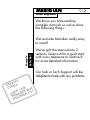
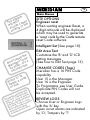
Dear Engineer
We know you hate reading
complex manuals so we've done
the following things:
We've made Meridian really easy
to install
Example
Refer B63
'A'
We've split the manual into 2
sections. Section A for a quick start,
with cross reference to Section B
for more detailed information
Our lads in Tech Support will be
delighted to help with any problems
T
UL
A
F
DE DES
4
CO
2
123 222 1
R
1
E
ER
US NAG ER 11
MA GINE
EN
2A1
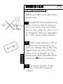
Wiring Instructions
Before you start, remember these
basic rules:
1. As with all other professional
Data Communication Systems
Don't run more than one data
pair in any cable (ie Don't mix
ID, Keypad, Telecom, Speakers
etc in the same cable sheath)
Refer B22
IR
=
V
2. Ohm's Law applies in Alarm
Systems too! Long cable runs
will lose voltage along the way
depending on the load at the
other end, so double up on
supply pairs, Bell/Speaker drives
and even iD bus if necessary.
3. But never double up the
TX/RX on RS-485 keypad
cables!
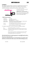
3A1
The End Station
Mount the End Station using 3
fixing screws.
Refer B49
T
US
M
l lid
e
n
pa ectly afety
e
h
T corr for s
be thed
ear sons
rea
Wire the mains to the mains
connector block through the
mains inlet access hole.
CAUTION: Mains electricity is
dangerous, installation should
be by a competent electrician.
Fuse
150mA
DON'T loop the mains wire in
the box, or enter through a
different hole, it may affect
Meridian's EMC performance!
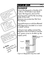
4A1
The keypad
pad
y
e
k
achent
e
r
re
de
Co a diffe befo
to ress p
addwer u
po
d
ess lose
r
d
c
Ad All pen
Ø = A1 o pen
1 = A2 o open
2 = A1/2
3=
eer ss 3) n
n
i
e
Eng(Addr Statio
g
Plu pad End ed.
key o the requir
ont B as
PC
3
te: d No. d
o
N pa
se
key ot be u
n
can ne
alo
Mount the keypad so that the LCD
is about 10cm below eye level.
Open the keypad, remove the
securing screw and fix the mounting
plate to the wall.
Remove any protective film from
the display
Tag performance could be affected
if the keypad is mounted on or near
a metal surface.
Using 6 core cable connect the
keypad to the End Station (use the
two spare cores to double up the
supply pair)
Meridian End
Station
Keypad
Keypad
Up to 4 keypads may be used.
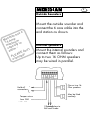
5A1
Outside Sounders
a
as
h
ian
rid p
e
M Am m
1.5 ximu in
ma acity
cap rm t
on'
ala
d
E
AS d!
E
PL rloa
ove
Mount the outside sounder and
connect the 6 core cable into the
end station as shown.
Internal speakers
Mount the internal sounders and
connect them as follows:
Up to two 16 OHM speakers
may be wired in parallel.
One or two 16
Ohm speakers
Hold off
connections
May be fitted
remotely
Tamper return
from SAB
0 v connections to
Bell and Strobe
6A1
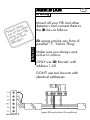
iD wiring
Mount all your PIR and other
detectors and connect them to
the iD bus as follows:
n't le
o
d
se, iD cab 0
a
e
Pl an an 10
run re th rom
mo tres f
me ridian
Me
Refer B 23
iD wiring can be any form of
parallel - 'T', 'Star'or 'Ring'.
Make sure you always wire
colour to colour.
ONLY use 'iD Biscuits' with
address 1-20
DON'T use two biscuits with
identical addresses
Typical PIR used with an iD wired Biscuit
Meridian PCB
7A1
That's it! You've wired up
Meridian as simply as that.
Refer B 25/26
If you've done it correctly
Meridian will work first time.
If not, see page B25 for possible
faults.
8A1
Powering up Meridian
tic
las d
e
the vide to
p
o
o
Lo d pr PCB
ban r the he
h
ove ure t switc
sec per
Tam
,
rity
u
c
se ALL lt
r
o
F nge fau
cha se de
the es
cod
p
chi ed
M
NV e fitt to
e
h
T ST b dian ly
MU Meri rrect
for rk co
wo
Double check wiring is correct
and no wire - whiskers are
shorting together.
Secure the panel tamper switch
otherwise a Tamper Alarm will
occur at Power Up.
Power Up with Mains and/or
Battery.
Silence any alarm using the user
code 1234.
Default codes:
USER
1234 (code 1)
MANAGER 2222 (code 15)
ENGINEER 1111 (code 16)
9A1
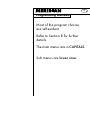
Programming Meridian
Most of the program choices
are self-evident.
Refer to Section B for further
details.
The main menus are in CAPITALS.
Sub menus are lower case.
10
A1
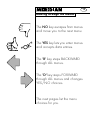
Moving through the Menus
The NO key escapes from menus
and move you to the next menu.
"O
K"
The YES key lets you enter menus
and accepts data entries.
The 'B' key steps BACKWARD
through ALL menus.
The 'D' key steps FORWARD
through ALL menus and changes
YES/NO choices.
The next pages list the menu
choices for you.
11
A1
Menus Summary
PA tinue
d
n
n
e a ts co
r
i
...
F cui
e
n
i
cir work r mod
to inee
eng
t in s
p
e
xc zone
e
.
. . nge d
cha nu an tics s
me gnos menu
dia play
dis
SET SYSTEM?
CLEAN START?
CHANGE ZONES?
- Types /Attributes/Text
CHANGE TIMERS
- Bell/Delay/Strobe
- Exit/Entry/Re-arm
SET DATE AND TIME?
EXIT MODES?
- All/B Set/D Set
SOUNDER VOLUMES?
- Chime/Exit/Entry
- Silent/Part Set
ALARM RESPONSE?
ALL/B Set/ D Set/Fire Set
CHANGE CODES?
CHOOSE OUTPUTS?
SITE OPTIONS?
- Engineer Reset
-Intelligent Set
- Edit Area Test
REVIEW LOGS?
CLEAR LOGS?
WALK TEST?
EXIT ENGINEER?
12
A1
Main Menus
SET SYSTEM
Meridian will ignore all detectors
while setting - once set, the first
active detector trips the alarm.
ou !
y
s
er this !
e
n
y
gi
En ST tr
MU
CLEAN START: Key in 2000 to
return the programme to factory
defaults.
e
hes t
t
f
c
o
ne sele
o
y in s to
Ke mber type
nu zone
the uired
req
or
Refer B 27
the
h
g
rou e
h
t
th
p
ys
Ste with B' ke
list and '
'D'
CHANGE ZONES
Zone Types
00 - Fire
01 - PA
02 - Silent PA
03 - Tamper
04 - Intruder
05 - Entry/Exit
06 - Walk Through
07 - EE/Walk Through
08 - Exit Terminator
09 - Isolated
10 - Keyswitch sets A
11 - Keyswitch sets B
12 - Keyswitch sets D
13 - Shunt
13
A1
Refer B 31
Change zones continued
our e
y
E
h
NG with t
A
CH ice
cho key
our the
'D'
y
t
ith
cep
Ac ice w y
cho S' ke
'YE
Zone Attributes
Active in B
Active in D
Intelligent arming (see page 18)
Anti -Mask
Soak Test
Chime
Omittable
Pulse keyswitch
Refer B 33
How to Edit Text
Use the 'B' and 'D' keys to move
the cursor back and forth.
Delete a letter with the 'C' key.
Numeric keys step through the
alphabet.
Key 1 gives ABCD
Key 2 gives EFGH etc.
14
A1
Main Menus
Key in the appropriate
numbers to provide the
response you require in the
following menus:
Refer B 34
CHANGE TIMERS?
EXIT MODES?
00 - Timed
01 - Terminator ( Push to set)
02 - Final Door
03 - Quick Set
Refer B 35
ese
h
t
of ake
e
n
in ors to m
y
Ke mbe oice
nu r ch
you
SOUNDER VOLUMES?
01 - Bleepers
02 - Adjustable
03 - Full alarm
the
h
g
rou e
h
t
th
p
ys
Ste with B' ke
list and ' your he
'D' cept ith t
Ac ice w
cho S key
YE
Refer B 36
or
ALARM RESPONSES?
01 - Keypad
02 - Sounder
03 - Sounder and bells (local)
04 - Full alarm
05 - Graduated Sound
06 - Graduated Local
07 - Graduated Full
15
A1
or
m
om be
C
i
Dig U can on tor
ST gged ins o ia
plu lex P one v
Mo nd al face
sta inter
an
Refer B 38
ay
m
t
u
d
utp mme U
o
h
T
ra
Eac prog digi/S 10
be the 9 tput an
to s, ou eridi 6
PIN the M d the puts
on B, an D out
PC ote i
rem
put
t
u
o
h
the u wis
n
i
yo
y
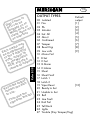
Ke ber
numuse.
e
to
k this list
c
i
n p m th
e
h
T e fro
typ
OUTPUT TYPES
00
01
02
03
04
05
06
07
08
09
10
11
12
13
14
15
16
17
18
19
20
21
22
23
24
25
26
27
Default
output
[1]
[2]
[3]
[4]
[5]
[6]
[7]
[8]
[9]
Isolated
Fire
PA
Intruder
Set: All
Abort
Confirmed
Tamper
Reset Digi
Low volts
Mains Fail
B Set
D Set
B Alarm
D Alarm
Shunt
Shunt Fault
Latch 1
Latch 2
[10]
Viper Reset
Ready to Set
Unable to Set
Bell
Line Fault
Batt Fail
Tell Back
Lights
Trouble (Day Tamper/Eng)
16
A1
Main Menus
tem
s
y
s
The l NOT odes '
wil ept c n '00
acc ing i
end
SETTING D
STOREROOM
the
e
v
e
a
t le r Cod a
'
n
Do nage - it's
Ma 2222 risk
as urity
sec
to
'C' ode
s
s
c
Pre ete a
del Tag
or
lly
tica de’
a
o
om
aut nge C timer
m
a
e
d
t
a
h
sys ‘ C y of mme
The ts from expir rogra very
exi nu on the p is is ay be
me ed to . If th ties m
link t time fficul hen s.
Exi rt, di ced w code
sho erien ming
exp gram
pro
SITE OPTIONS
Engineer reset
When waiting engineer Reset, a
4 digit anticode will be displayed
which may be used to generate
a ‘reset’ code by the Castle remote
reset Code software
Intelligent Set (See page 18).
Edit Area Text
Customise the 'B' and 'D' LCD
setting messages.
(See how to Edit Text page 13).
CHANGE CODES (Tags)
Meridian has a 16 PIN Code
capability.
User 15 is the Manager.
User 16 is the Engineer.
To Programme, see User Guide.
Duplicate PIN Codes will not
be accepted.
REVIEW LOGS
Choose User or Engineer Logs
with the 'A' key.
Open circuit alarms are indicated
by 'O', Tampers by 'T'.
17
A1
False alarm management
e as
l
b
aila der'
v
a
rt is 'Intru s a
o
b
A tore or a al
res de 3) sign
(co arate
sep
Meridian has a sophisticated
false alarm management system
to help the user quickly realise
and correct any mistakes made.
1. An Abort signal will be sent
whenever Meridian is switched
off following an Intruder Alarm.
nal
g
i
ill s ond
w
irm e sec
f
n
Co en th e is ing
wh id zon nclud
val ped i
trip pers
Tam
2. Confirmed signals will be
stored and not sent for 3 minutes
if any Alarm occurs within 3
minutes of Set, or for 3 minutes
following deviation off the Entry
Route or Entry Time out.
rm,
A
e
a R is
g
in ion
nd
w
2
o
t
l
n
Fol firma whe ripped
con ilable e is t
ava id zon
val
3. Delay Bells are cancelled
for 3 minutes after Set, and
following an Entry Alarm.
18
A1
Refer B 42
Intelligent Arming
o
fe s for
i
l
s
r
ake asie
m
It ch e !!
mu user Tag
the code/ - no t
ll
Se
e
On es it a part
do plex
com tines
rou
In simple terms intelligent arming
allows Meridian to intelligently
determine whether the user is
leaving the house - and therefore
requires full set, or is going to bed
- and needs part set.
To permit this simple 'function' all
you need to do is:
Position a PIR detector that detects
the user at (say) the top of the
stairs in the vicinity of the
bedroom.
This detector must have the
'Intelligent' Zone attribute as 'YES'.
The detector acting as the final
exit zone (eg. front door), which
is active in Part Set ‘B’, should
have the ‘Intelligent’ zone attribute
as 'YES'.
Refer B 42
19
A1
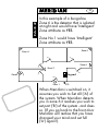
In this example of a bungalow
Zone 6 is the detector that is isolated
at night and would have 'Intelligent'
Zone attribute as YES.
Zone No.1 would have 'Intelligent'
Zone attribute as YES.
Zone 5
Zone 4
Zone 6
Zone 2
Keypad
Zone3
Zone 1
PTS
When Meridian is switched on, it
assumes you wish to Set All ('A') of
the system. When Meridian detects
you in zone 6 it realises you wish to
set part ('B') of the system - and does
so. (If you go back to the front door
Meridian will realise that you have
changed your mind and set full
('A') again!).
20
A1
We hope you enjoyed
installing Meridian
If you have any ideas or grouses,
call us on
01344 886446
or
for Technical Assistance
call
But please be gentle with us, it
may have been a hard day!
MERiDIAN
Index to Section B
Additional Information
DEFAULT SETTINGS
WIRING NOTES
21
System Wiring
22
iD Wiring
23
iD Commissioning Readings
24
IF IT DOESN'T WORK ...
25
Faultfinding an iD System
ZONE TYPES
27
Shunt Zones
28
Keyswitch Zones
29
ZONE ATTRIBUTES
31
Anti-Masking
32
TEXT PROGRAMMING
33
EXIT MODES
34
SOUNDER VOLUMES
35
ALARM RESPONSES
36
INPUTS
OUTPUTS
37
Specifications
38
Types
39
REMOTE SIGNALLING
41
INTELLIGENT SETTING
42
TESTS & DIAGNOSTICS
44
PRINTING
45
SYSTEM SPECIFICATIONS
46
Printed Circuit Boards
CE MARKING DIRECTIVE
Issue 3b
26
47
49
January 2000
MERiDIAN
21
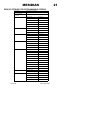
DEFAULT SETTINGS FOR PROGRAMMABLE OPTIONS
Zone types
All zones are isolated
Zone attributes
All attributes are OFF
Zone text
All texts default to "Zone
Timers
Bell duration
15 minutes
Bell delay
0
Strobe duration
0
Exit time
40 seconds
Entry time
45 seconds
Re-arm count
3 times
ALL set
Terminator
B set
Timed
D Set
Timed
Chime
Full volume
Exit
Adjustable
Entry
Adjustable
Silent Part Set
ON
ALL set
Full alarm
B set
Sounder and bells
D set
Sounder and bells
Fire
Sounder and bells
1
Fire (01)
2
PA (02)
3
Intruder (03)
4
Set All (04)
5
Abort (05)
6
Confirmation (06)
7
Tamper (07)
8
Reset Digicom (08)
9
Low Volts (09)
10
Viper Reset (10)
11-16
Isolated (00)
Engineer Reset
OFF
Intelligent Setting
ON
Exit modes
Sounder Volumes
Alarm Responses
Outputs
Site Options
Codes
1 (User)
2 - 14
Issue 3b
"
1234
NOT programmed
15 (Manager
2222
16 (Engineer)
1111
January 2000
MERiDIAN
22
SYSTEM WIRING
The system keypad communications use RS.485 protocol, which is
designed to be used with cabling installed to the following specification
Cable type:
Twisted Pairs (Min 4 cores)
eg CQR 'Twisted Pair cable'
Wiring
configuration
Parallel, in 'Daisy-Chain'
configuration
ie Spurs and Star
configurations are not
recommended.
Terminations
680 ohm resistor wired between TX and RX terminals of the
equipment at each end of the RS.485 link
Wiring Distance
Maximum overall length of RS.485 link should not exceed 1
Km
NOTES: For keypads in excess of 10 metres of End Station, 6- or 8- core cable is
recommended, with additional cores being used to double (or treble) supply
connections for minimum voltage drop.
Keypads in excess of 100 metres from End Station should be separately
powered.
Systems using relatively short cable distances, in electrically 'quiet' environments'
may successfully use simpler wiring configurations, and use standard alarm
cable.
The iD system used for detection should be wired as follows
Up to 100 metres
per cable run
4 cores
Additional cores are
recommended to double
up supply to minimise
voltage drop
Screened cable preferred.
Standard alarm cable may be
used in clean environment.
Do NOT use highly capacitive
cable, such as 'PYRO' etc.
NOTES
Do NOT run any of the above connections in the same cable as, or close to,
each other or other AC signals, such as telephone, loudspeaker, etc. cables
unless screened cable is used.
Screened cable should be terminated with the screen connected to earth
(metalwork) at one end only, as close as possible to the point of entry into the
housing
Under no circumstances should system cabling be run with MAINS cable, as this
contravenes BS.4737 and the Electrical Wiring regulations.
On completion of wiring, measure the AC voltage between 12v supply
terminals and mains earth. If this exceeds 1 volt, connect End Station 'Gd'
terminal to mains earth to introduce AC Noise filtering.
Issue 3b
January 2000
MERiDIAN
23
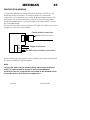
iD WIRING
Each detector must be wired to an iD biscuit, and wired back to the panel in
any parallel configuration. Each biscuit has an address number. Devices
numbered between 01 and 20 may be used, but under no circumstances
should any number be duplicated. The detector is wired as follows:
iD Line + (YELLOW)
Tamper Switch
07
iD Line - (BLUE)
Switch
(WH ITE)
wire
It should be noted that the biscuit
may also be operated
magnetically, in which case the
WHITE wire is not connected. For this
reason, care should be taken if siting
a biscuit close to a loudspeaker, or
other strong magnetic field.
Detection
CABLE SPECIFICATIONS:
Cable type:
Wiring format:
Cable length:
Cable routing:
Biscuit location:
Screened
Any parallel configuration
Max 100 metres for any cable run
Must NOT be run with other cables carrying AC or digital signals
Must be wired directly to detector terminals
If this is impossible, a 'DP' junction box should be used.
Checks:
Warning:
All commissioning checks must be performed and recorded
In some situations, especially take-over sites using existing
wiring, iD technology may not be suitable.
To simplify connections, junction boxes are available as follows:
iD 'T'
For simple cable extension, or 'T' junctions
iD 'DP'
NEW VERSION
Accepts a wired biscuit and provides a double pole circuit for the
connection of a detector(s). There is no practical limit to the wiring
length of this circuit.
NOTE: Original DP junction box, accepting plug-in biscuits, did NOT
provide a true 'tamper' loop, being designed for self-protecting
zones (eg 24Hr tamper zones, PA zones, etc.).
When allocating biscuit numbers, ensure that any 'Walk Through' zones
are allocated to biscuit numbers adjacent to, and higher than, the 'Entry
Exit' zone to which they refer.
It will be found beneficial to keep a record of the biscuits used, and the order in
which they are wired (on the various spurs) to assist with fault finding (see p.26)
Issue 3b
January 2000
MERiDIAN
24
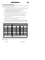
iD Commissioning Readings
The following procedure is recommended to provide the measurements
expected, to comply with BS.4737.
1.
Before finally securing the detector housings, remove the Yellow and Blue (iD+ and
iD-) wires from the End Station (p.26 Fig 1 points A and B), and twist them together.
2.
At the end of the first wiring leg (point C), measure and record
(a) The resistance between the Yellow and Blue (L+ and L-) connections
ENSURE that this reading is correct for the cable length involved.
(b) The supply voltage at the detector (if applicable)
3.
Secure the detector housing, ensuring that the tamper switch is correctly closed.
4.
Repeat steps 2(b) and 3 for each appropriate detector on that wiring leg.
5.
Move to each of the other wiring legs (point D, E), and repeat steps 2 to 4
6.
Separate the Yellow and Blue wires at the End Station, measure and record the
resistance between them.
7.
Check for leakage between iD cable and mains earth, also to 12v supply
8.
Replace these wires in the appropriate terminals.
9.
Measure and record the system voltage at the End Station, Keypads and SAB unit.
10. Measure and record the standby and alarm currents, by inserting the meter (set to
current rang in series in the battery '+' lead, and disconnecting the mains supply.
The following readings should be anticipated:
Step 2(a)
Wiring resistance only (max 10 ohms per 100m)
Step 6
Resistance of iD network, as follows:
No of
biscuits
Approx.
resistance
No of
biscuits
Approx.
resistance
No of
biscuits
Approx.
resistance
1
87K
8
10.9K
15
5.8K
2
43.5K
9
9.7K
16
5.4K
3
29K
10
8.7K
17
5.1K
4
21.8K
11
7.9K
18
4.8K
5
17.4K
12
7.3K
19
4.6K
6
14.7K
13
6.7K
20
4.4K
7
12.5K
14
6.2K
Step 7
Open circuit resistance measurement to earth, no
voltage to supply connections.
NOTE: These measurements are useful for verifying system integrity. They should
NOT be considered as diagnostic measurements for individual biscuits, due to
the fact that these are semi-conductor devices, and exhibit a wide range of
resistance values.
Issue 3b
January 2000
MERiDIAN
25
IF IT DOESN'T WORK ....
PROBLEM
POSSIBLE CAUSE
System will not initialise
correctly
No NVM fitted
Incorrect voltage at End Station, or at
Keypad
Wiring fault on RS.485 between End Station
and Keypad(s)
Keypads not address coded correctly
Response to detectors
incorrect
Are zone types and attributes correctly
programmed?
Systems sets in Part
instead of Full (or vice
versa
Intelligent Setting not correctly
programmed, or programmed when not
required (see p.42)
Communicator / STU not Trigger outputs not programmed correctly
signalling correctly
(see p.41) or communicator programmed
for incorrect channels or polarity
No power to detectors
'iD' Fuse blown
SAB Tamper fault
'Bell / Strobe' fuse blown
SAB Tamper return missing or incorrect
polarity (requires 0v return)
No bell delay following
alarm
Bell delay is cancelled for 3 minutes
following system set, or entry
No confirmation
following alarm
Confirmation not valid within 3 minutes of
set or entry.
Speakers not sounding
during exit time
Speakers interrupted during 'zone omission'
routine
For first 10 seconds of exit time, sound is
present on keypad bleepers ONLY.
Speakers not sounding
at all
'Speaker' fuse blown
Bells (and
communication)
delayed after alarm
Alarm response set to 'Graduated'
Faults on iD Circuitry
See page 26
Issue 3b
January 2000
MERiDIAN
26
FAULTFINDING AN iD SYSTEM
A
01
10
05
14
08
C
09
02
07
12
04
D
15
13
06
03
11
E
B
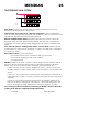
A sample iD
system diagram
False Alarms. If these are not reported as tampers, normal checks on the
detector and siting should be performed.
Tamper alarm caused whenever a detector is triggered is almost certainly the
result of the iD biscuit being wired with the detection (switch) connection in the
YELLOW wire instead of between WHITE and BLUE.
Random multiple tamper alarms (including twin devices) can be caused by
having a switch contact wired between WHITE and YELLOW. It can also be
caused by the system voltage being dragged low by current overload, eg in
alarm.
If the entire iD system is showing tamper faults, or 'iD Line Fault' the line may be
overloaded (too many biscuits attached), or there is a cable short, or leakage
to supply or to earth.
Other tamper alarms can be caused by
a) a tamper switch open, or broken cable or connection
b) two biscuit reporting at the same address
c) a faulty biscuit
BEFORE looking for the fault, check the system diagnostics to ascertain the full
picture of biscuits showing tamper faults. For example, referring to diagram
above, suppose that a tamper alarm has been generated by zone 2:
If zone 2 alone is in fault, and the diagnostics show 'F' (Open Circuit), the
problem will be a tamper switch open, poor connection or faulty biscuit at
zone 2.
If zones 4, 7 and 12 also show a tamper fault, the problem is a break in the
cable between 2 and 9, or a poor connection at either the zone 2 or zone 9
detector.
If zone 13 (say) is also showing a tamper fault, the problem is likely to be
that one of them is reporting as 'twin device' - check the diagnostics, the
biscuit showing 'F' (missing) will either be the wrong number, or faulty.
Thus checking for the overall picture, and having available a sketch of the order
of wiring of the biscuits, will greatly simplify fault finding.
Issue 3b
January 2000
MERiDIAN
27
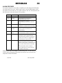
ZONE TYPES
Each zone (iD point) on the system may be programmed to any of the
available zone types, by entering the relevant selection code:
Code
Zone type
Notes
00
Fire
01
PA
To prevent spurious retriggering, PA zones
remain inactive after engineer reset until
system set and unset.
02
Silent PA
This function is also available from the
keypad using the '4' and '6' keys (see
User manual )
03
Tamper
04
Intruder
05
Entry Exit
06
Walk Through
07
Walk Through / EE In 'ALL' set,
functions as
'Walk Through'
zone, in Part set,
functions as
'Entry Exit' zone
08
Exit terminator
09
ISOLATED
10
Keyswitch sets A
11
Keyswitch sets B
12
Keyswitch sets D
13
Shunt
For 'Push to Set'
button or
equivalent. See
p.34
These zone types
should be allocated
to biscuit numbers
adjacent to and
higher than the
'Entry Exit' zone
Normally OPEN push
button
When one of these zones is OPENED,
the system will set. CLOSING the zone
will unset the system - see p.30
Whilst this zone is CLOSED, all zones
programmed into its 'shunt list' will be
shunted out of operation. See p.28
Only ONE shunt zone may be selected
per system.
For additional information on zone types, refer to 'Shunt Zones' 'Keyswitch
Zones' and 'Exit Modes' pages, also to 'Zone Attributes'
Issue 3b
January 2000
MERiDIAN
28
SHUNT ZONES
The shunt facility may be used to control a zone, or group of zones, whilst
the system is set, as follows:
PROGRAMMING:
1.
Wire the zones to be used in the normal way. The zone to be used
as the shunt control should be numbered lower than the shunted
zones, and be wired so the switch (lock) contacts are CLOSED
when the shunt is to be applied (ie when the shunted zones are to
be INACTIVE).
2.
Program the zones to be shunted in the normal way. The system
will permit shunting of zones programmed as 'Entry Exit, Walk
Through, Intruder, or Tamper.
3.
Program the zone to be used to control the shunt as zone type 13
(shunt) after programming the other zones. The display will show
Shunt List?
Press 'YES' to select, and the display will show
Shunt zones = _ _
None
Key in the number of the first zone to be added to the shunt list,
followed by 'YES.'
The programmed zone text will appear on the second line, in
place of 'none' - and the display will await the addition of further
zones. The display will cycle through all zones added to the list.
Re-entering the number of a zone already included will result in it
being deleted from the list.
A final 'YES' will terminate the selection, and permit any
appropriate zone attributes to be programmed.
To clear the shunt list completely, press the 'C' key.
4.
The system is now ready for use.
5.
ONE shunt only may be used per MERiDIAN system, but there is no
limit to the number of zones which may be shunted.
NOTE: If reallocating a 'Shunt' zone to a different type, it is essential that
the 'shunt' is cleared (ie all zones are live) BEFORE entering engineer mode
to perform the change.
Issue 3b
January 2000
MERiDIAN
29
Operation of Shunt Zones
In operation, whenever the 'shunt' zone is CLOSED, the zones
programmed onto the 'shunt list' will be inactive. On opening the zone,
the zones will be reactivated after a 10 second 'setting' period. In the
event of a shunted zone remaining in fault condition, the shunt will
remain in force until it clears.
Outputs may also be programmed to function in conjunction with the
'shunt' operation as follows:
Output type:
15 Shunt
May be used to drive an indication live
throughout the time that the shunt is
applied (ie zones are inactive)
16 Shunt fault May be used to drive an indication (or
buzzer) to draw attention to the fact that
the shunt is being released. This will be
live for approx. 10 seconds, unless a fault
exists on a shunted zone, in which case
the output will pulse, and will remain live
until the fault is cleared.
Refer pages 38 - 39 for specifications of outputs used.
Issue 3b
January 2000
MERiDIAN
30
KEYSWITCH ZONES
1.
Wire the keyswitch between the BLUE and WHITE connections of
the iD biscuit.
The contacts should present an OPEN circuit to the biscuit when
the system is to be set, and CLOSED to unset.
2.
Program the biscuit to be a 'keyswitch' zone.
Note that alternative programs are available for setting 'All' 'B' or
'D' - the function keys are NOT available when using a keyswitch.
3.
If required, set the 'Pulse Keyswitch' attribute as ON.
If this is done, the system will set on the first OPENING of the
keyswitch, and Unset on the second OPENING - with the switch
having been closed in between - as for example when using a
sprung keyswitch.
4.
The keyswitch and Keypad may be used interchangeably, EXCEPT
that the keyswitch cannot be used to unset from a mode different
from that for which it is programmed (see 6)
5.
The 'Omittable' attribute should be set as 'NO' to prevent the
keyswitch from being accidentally omitted when setting from the
keypad - unless this feature is required.
6.
In the case of a keyswitch programmed as 'A' with zone attributes
'Active in B' and 'Active in D' set as ON, it WILL be possible to unset
with the keyswitch if the system is partially set.
Issue 3b
January 2000
MERiDIAN
31
ZONE ATTRIBUTES
The operation of each zone may be adapted to individual requirements
by selecting attributes from the following
Attribute
If 'NO' selected
(default)
If 'YES' selected
Active in B Zone is automatically
omitted if system is
Active in partially set (B or D as
appropriate)
D
Zone is LIVE when the
system is partially set (B
or D as appropriate)
Omittable Zone CANNOT be
manually omitted
whilst setting. (Does
NOT affect automatic
omission in Part set)
Zone can be manually
omitted.
Chime
Zone will cause system to
'chime' if in 'Chime'
mode (ie 'C' set).
Soak Test
-
Zone will function
normally
Zone will NOT trigger an
alarm, but will indicate
and log.
Intelligent System will set
conventionally
System setting will be
modified according to
triggering of 'Intelligent
Set' zones. See p.42
Pulse
Keyswitch zone will set
Keyswitch system on OPENING
circuit, and unset on
CLOSING
Keyswitch zone will set
system on first OPENING
of circuit, and unset on
NEXT OPENING, after
closing in between. See
p.30
Anti-Mask
Anti-Mask monitoring will
be implemented, and
indicate on setting the
system. See p.32
Issue 3b
-
January 2000
MERiDIAN
32
ANTI-MASKING
Any zones programmed with the 'Anti-Mask' attribute will be monitored
whilst the system is unset.
If the zone has NOT been activated since the system was last unset, then,
on attempting to set the system, the display will show
Zone xx
may be masked
If more than one zone is affected, these will scroll repeatedly.
Diverting from the exit route to test these detectors will automatically
clear them from the display, and abort the setting procedure.
Press 'NO' to abort the setting procedure and test the detectors in
question.
Press 'YES' to override the warning and set the system.
If this is done, the system 'User Log' will show an entry
Mask override
This will be located immediately AFTER the appropriate 'set' entry (ie
earlier in time' when the log is viewed.
Issue 3b
January 2000
MERiDIAN
33
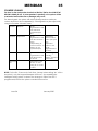
TEXT PROGRAMMING
When programming text, the keys on the keypad are used as follows
ABCD
EFGH
IJKL
1
2
3
MNOP QRST
UVWX
A
ç
4
5
6
B
YZ , -
. / 01
2345
Clear
7
8
9
C
è
6789
NO
0
YES
D
NOTES:
NO key
YES key
Accepts the text string as programmed, and returns to
zone selection menu
'B' Key
Moves cursor one position to the RIGHT
'C' Key
Clears any character from the cursor position, and moves
one position to the right, thus inserting a space.
'D' key
Moves cursor one position to the RIGHT
Issue 3b
January 2000
MERiDIAN
34
EXIT MODES
EXIT TERMINATOR / PUSH TO SET
1.
Wire the terminator device (eg push button) between the BLUE
and WHITE connections of the iD biscuit. The connection should
be CLOSED momentarily to activate.
2.
Program the biscuit as an 'Exit terminator' zone (type 08), ensuring
that the 'Omittable' attribute is set to 'NO'
3.
The system will set when the exit terminator is closed during exit
time.
4.
If the 'Push to Set' function is required to function when 'Part'
setting, the 'Active in B' and 'Active in D' attributes should also be
set as 'ON'
FINAL DOOR SET (Valid for 'ALL' set only)
1.
For use with a contacted lock, to set the system when the lock
contacts are closed, and start entry time when they are opened.
In this application, a separate door contact should be provided,
programmed as 'Walk Through' for maximum security.
2.
Alternatively, a single contact on the door may be programmed
as 'Entry Exit' in the normal way. The system will set when the door
is opened and re-closed.
QUICK SET (Valid for Part Set 'B' and 'D' only)
1.
The system will set after an abbreviated (5 second) exit time.
NOTE: For the first 10 seconds of exit time, (except when setting 'ALL' with a
keyswitch), only the keypad bleepers will sound - thus enabling the
intelligent setting system to detect the change to 'Silent Part Set' if
programmed, before the system sounders become live.
Issue 3b
January 2000
MERiDIAN
35
SOUNDER VOLUMES
The load on the loudspeaker terminals at the End Station should NOT fall
BELOW 8 OHMS (ie two 16 ohm speakers in parallel) or the system will be
overloaded and malfunction or damage may result.
For alarm signals, the system will automatically produce maximum
volume level from the loudspeaker(s). Other signals may be adjusted by
using the 'Sounder Volumes' menu.
Level 01
Bleepers
Signals
programmed to this
level will sound
keypad bleepers
ONLY
Level 02
Adjustable
Signals
programmed to this
level will sound the
system
loudspeaker(s) at
reduced volume - in
addition to the
keypad bleepers
Adjusted by
control on End
Station pcb (see
p.47).
Adjustment
applies to ALL
signals
programmed to
this level.
Level 03
Maximum
Signals
programmed to this
level will sound at
full volume
All alarm signals,
including
tamper, are fixed
at this level.
Silent Part
Set
If selected as 'YES'
exit time on Part
Setting 'B' or 'D' will
be silent.
NOTE: For the first 10 seconds of exit time, (except when setting 'ALL' with a
keyswitch), only the keypad bleepers will sound - thus enabling the
intelligent setting system to detect the change to 'Silent Part Set' if
programmed, before the system sounders become live.
Issue 3b
January 2000
MERiDIAN
36
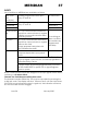
ALARM RESPONSES
The system response to an alarm condition may be selected individually
for each level of set ('ALL' 'Part B' and 'Part D'), and for FIRE alarms whilst
the system is other than 'ALL' set (when system is 'ALL' set, Fire response will
be the same as the remainder of the system).
Selection
Option
Notes
01
Keypad
Keypad bleepers ONLY will sound
02
Sounder
Keypad bleepers, and system
loudspeaker(s) will sound
03
Local
Keypad bleepers, system
loudspeaker(s) and external bell will
sound
04
Full
The communicator output will be live,
in addition to all the above sounding.
05
Graduate
Sounder
Keypad bleepers will sound for 15
seconds, then be joined by the
loudspeaker(s).
06
Graduate
Local
As option 05, with the external bell
activated after a further 15 seconds.
07
Graduate
Full
If PART SET
As option 06, with communicator
output live after a further 15 seconds
(ie delay from alarm to triggering of
communicator is 45 seconds).
IF FULL SET
If alarm created by an entry fault
(expiry of entry time, or deviation from
entry) system will respond as in PART
SET.
If normal intruder alarm created,
system will respond as option 04 (ie
immediate full output).
GRADUATED responses apply to initial setting only - in the event of a
further alarm being generated after the system has 're-armed' the
responses will be immediate.
Issue 3b
January 2000
MERiDIAN
37
INPUTS
Input facilities on MERiDIAN are available as follows
Push to Set
(exit
terminator)
Suitably programmed zone input.
See p.27 and 34
Exit terminator
Keyswitch A
Suitably programmed zone inputs.
See p.27 and 30
Keyswitch A
Keyswitch B
Keyswitch D
Keyswitch B
Keyswitch D
Communicator Pin 7 on Communicator connector.
Fail
Signal from communicator to register
inability to communicate with Alarm
Receiving Centre
If live during an
Line Fault
Pin 15 on Communicator connector. alarm condition,
Signal from communicator to register will override any
programmed
telecom line fault.
bell delay.
System response harmonises with
NACOSS directive NAD.1
Tellback
Pin 6 on communicator connector.
Response dependant upon panel
status
If system in ALARM condition, functions as 'TELLBACK' to
log that digital communicator successfully signalled to
Alarm Receiving Centre.
If system Unset, and waiting Engineer Reset, functions
as 'RED CARE RESET' to permit STU to signal Engineer
Reset to system
NOTE: Communicator inputs are designed to accept signals which are 0v,
switching to +5v when active.
Telecom Line Fault Response with System unset:
The internal sounders will be live. This may be cancelled by entering the
4-digit pin code. The display will show 'Telecom Fault' until the fault clears.
If the fault recurs before the system is again set, the indication will return,
but the sounders will NOT retrigger.
Issue 3b
January 2000
MERiDIAN
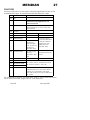
38
OUTPUTS - SPECIFICATIONS
The MERiDIAN system has a total of 19 outputs available, as follows
BELL
Terminal at End
Station
Normally +12v (via 1K),
switching to 0v when live.
Max current 400mA
STROBE
Terminal at End
Station
Normally +12v (via 1K),
switching to 0v when live.
Max current 400mA
SPEAKER
Terminals at End
Station
Normally +12v, -ive terminal
switched when live.
Max load must NOT fall
below 8 ohms (typ. 2 x 16
ohm speakers)
Outputs
1 to 9
Digicom plug-on
pins (see p.41 and
47)
Normally 0v, switching to +5v
when active.
No current available (logic
level only)
Output 10
Terminal at End
Station
Normally 0v, switching to
+12v when active.
Max current 65 mA when at
+12v
NOTE: when programmed as
Viper Reset, output is +12v
except during reset pulse
(see p.39)
Outputs
11 to 16
At add-on iD
Normally +12v (via 1K),
output modules (2) switching to 0v when active.
Max. current 400mA when 0v
Of these, Outputs numbers 1 to 16 are fully programmable, to any of the
output types shown on page 39. More than one output may be
programmed to each type, as required.
Each output module has 3 outputs, which are selectable by jumpers on
the module to be outputs 11, 12 and 13 or 14, 15 and 16 (see page 48)
Issue 3b
January 2000
MERiDIAN
39
OUTPUT TYPES
Selection
Type
Default to
o/p
Active
Restore
11 to 16
-
-
00
Isolated
01
Fire
1
At alarm
When silenced
02
PA
2
At alarm
When reset
03
Intruder
3
At alarm
At first code entry
after alarm
04
Set All
4
When system 'ALL' set When unset
05
Abort
(Mis-operation)
5
When system
silenced after
'intruder' alarm
At next code entry
06
Confirmation
6
When further zone
triggered after
'intruder' alarm
At next code entry
Applicable to Tamper, Intruder or Walk
Through zones only.
07
Tamper
7
Any tamper alarm
At reset
08
Reset Digicom
8
At power up
Live for 5 seconds
Must ALWAYS be allocated to output 8
when digital communicator is in use (NOT
required for STU)
09
Low Volts
9
At fault
When fault clears
10
Mains Fail
-
At fault
When fault clears
Also included in output type 27
11
B Set
-
When Part set B
When unset
12
D Set
-
When Part set D
When unset
13
B Alarm
-
When intruder alarm
whilst Part set B
On code entry
14
D Alarm
-
When intruder alarm
whilst Part set D
On code entry
15
Shunt
-
When the shunt zone When shunt zone
is closed (shunt
opened
applied)
Issue 3b
January 2000
MERiDIAN
16
Shunt fault
-
40
After 10 seconds, or
when zone faults
clear.
When shunt zone
opened (shunt
released)
If a shunted zone is in fault during this
period, the output will pulse until cleared,
or shunt reapplied.
17
Latch 1
-
When set (and in
Walk Test)
18
Latch 2
-
This is the inverse of type 17
19
Viper Reset
10
On alarm, or when
unset.
At output 10: Permanently +12v, dipping
to 0v for 5 seconds at switch on
If used other than at output 10, an
external relay must be used to switch +12v
supply.
20
Ready to set
-
At switch on
When set
21
Unable to set
-
If zone in fault during When zone clears
exit time
22
Bell
-
When bell output live When bell output
silenced
23
Telecom fault
-
When telecom line
fault signalled by
communicator
When fault clears
24
Batt Fail
-
When battery fault
detected
When fault clears
Battery test is performed every 30 seconds
Also included in output type 27
25
Tellback
-
When triggered by
communicator
26
Lights
-
Live during Exit AND Entry times
27
Trouble
-
Engineer access, OR
System fault
Issue 3b
When code
entered
When clears
January 2000
MERiDIAN
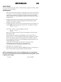
41
REMOTE SIGNALLING
The communicator output connections on MERiDIAN are compatible with any
industry-standard plug-on digital communicator or STU. Whilst these outputs may
be reprogrammed to any desired configuration (see p.39), the default settings
correspond with standard communicator configurations, so that in many cases
no programming will be required.
The output pins are numbered, top to bottom, 1 to 8 on the left hand connector,
and 9 to 16 at the right (see page 47).
PCB
Pin No
Prog
Digi channel STU channel Default setting
o/p No
1
1
1
1
Fire
01
2
2
2
2
PA
02
3
3
3
3
Intruder
03
4
4
4
4
Open / Close
04
5
5
5
5 or 7
Abort (Mis-Operation)
05
6
-
Input
Input
Tellback / Red Care
Reset
7
-
Input
8
9
L.Bat
L. Bat
9
-
-
-
+12v supply
10
-
-
-
0v supply
Not used C. Fail
11
-
Not used
12
-
-
13
6
6
14
7
7
6
15
-
Input
Input
16
8
Reset (8)
8
INPUT
INPUT
Low Volts
09
Not Used -
+5v supply
Not Used Confirmation
06
Tamper
07
Line Fault
INPUT
Digicom Reset
08
NOTES: All communicator outputs are +5v when active, and inputs require +5v to
trigger.
A 2000R interface may be used to provide a relay interface for PakNet, or to
trigger a stand-alone communicator. Alternatively, outputs from 'iD Output
Modules' may be used to trigger a stand-alone communicator, remembering
that these outputs will be 0v applied triggers.
Issue 3b
January 2000
MERiDIAN
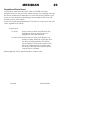
42
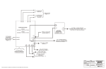
INTELLIGENT SETTING
PROGRAMMING.
The following chart will prompt the correct choices when programming
'Site Options' and 'Zone attributes.'
Is Intelligent arming required?
Site Options
For each
detector
NO
YES
Site option
'Intelligent
Set' = NO
Site option
'Intelligent'
= YES
Is the detector the one which must be passed
to enter the 'Part Set' area?
YES ***
NO
Zone
attribute
'Intelligent
Set' = YES
Is the detector the Final Exit zone?
YES
NO
Is the detector 'Active in Part B'?
YES
NO
Zone
attribute
'Intelligent'
= YES
Zone
attribute
'Intelligent'
= NO
Zone
attribute
'Intelligent'
= NO
*** - Do NOT use a Door Contact in this location
See page 43 for examples of implementing this.
Issue 3b
January 2000
MERiDIAN
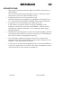
43
Examples of programming for Intelligent Set
1. A bungalow:
•
•
Z1=EE; Live B
Z2=WT; Live B
Z3=Int; Live B
‘ Z4=Int; Live B
Z5=Int;
Z6=Int; controls
'Part' area
•
Ž
Œ
Prog as
Intelligent?
= YES
= NO
= NO
= NO
= NO
= YES
2. A House:
Downstairs
•
•
Prog as
Intelligent?
•
Ž
Upstairs
Z1=EE; Live B
Z2=WT; Live B
Z3=Int; Live B
Z4=Int; Live B
Z5=Int; Live B
Z6= Int; controls
'Part' area
Z7=Int;
Z8=Int;
Z9=Int;
Œ
“
= YES
= NO
= NO
= NO
= NO
= YES
= NO
= NO
= NO
‘
’
”
NOTES:
The detector controlling access to the 'Part Set' area must NOT be a door
contact (if left open, the system cannot be 'Full Set.'
Issue 3b
January 2000
MERiDIAN
44
TESTS and DIAGNOSTICS
The following facilities are available within the Engineering menu
Output
Test
Press 'YES' to
Press keys 1 to 9 to activate
test outputs as individually the outputs on the
follows
communicator connectors
Press 'A' key to activate ALL other
outputs
Press '0' key to cancel outputs.
Display shows system voltage and current.
With all outputs OFF, this indicates system quiescent
current.
With 'All' outputs ON, system alarm current is shown
(except for communicator, if fitted)
Display
Zones
Press 'YES' to
display
current status
of ALL iD
biscuits
Display indicates:
c = Detector correct (normal) state
O = Detector in active state
F = Wiring open circuit (tamper)
T = Twin device (tamper)
NOTE: For Exit terminator zones, the 'normal' state (c)
is OPEN, and active state (O) is CLOSED
Bell Test
Press 'YES' to
activate bell
test
Display shows system voltage and
current
Press 'D' to
change to
Strobe test
Press 'D' to
change to
Sounder test
In each case the display shows the system voltage
and current whilst the test is in progress.
Press 'NO' to
terminate tests
NOTE: At each step, check that the current displayed is equivalent to that
expected, and there are no severe voltage drops.
Issue 3b
January 2000
MERiDIAN
45
PRINTING FROM MERiDIAN
To print from MERiDIAN, connect the printer interface (CT.3070) to the
RS.485 (Keypad) connections. This may be done as a permanent
connection, or a temporary one, via the 'Engineer Keypad' plug on the
End Station. This interface provides a connector for a PC compatible
Centronics parallel printer, such as the Epson P40, Seiko DPU40 or Datac
DP1014.0400K printers.
Ensure that the correct connecting loom (CT.5400 or CT.5500) is used, and
plugged on with the correct polarity.
Parallel printer connections
BROWN wire to TOP of loom
12v
0v
Rx
Tx
Supply connections
RS.485 communications connections
When viewing logs, pressing the 'C' key will direct the entries to the printer,
as well as scrolling through the display.
NOTE:
Owing to the wide variety of software driving requirements for different
printers, it is NOT possible for all types to be used with MERiDIAN.
Castle Care-Tech Ltd. regret that we are not able to offer detailed advice
for specific printers, other than those supplied by us.
Issue 3b
January 2000
MERiDIAN
46
SYSTEM SPECIFICATIONS
20 point iD detection zone alarm control system, all zones fully
programmable.
14 User codes, plus Manager and Engineer.
Accepts high security tags as an alternative to codes
Comprehensive keyswitch options
Full ('All') and two Part ('B' and 'D') Setting options
Intelligent setting selects 'All' or 'Part B' automatically
Programmed parameters and logs stored in 2416 NVM
Compatible with Castle Care-Tech 'NVM' programmer
226 event 'User log' plus 30 event 'Engineer log'
MAINS SUPPLY:
Nominal 230 - 240v AC
Max current 150 mA, Fused at 250mA
Power Supply
System voltage
13.75v DC
Continuous current 1.2A
Peak Current
1.5 A
Fused as shown on page 47
Current drain
End Station
Keypad (each)
Standby battery
Max 7 AHr. Must be connected at all times
45mA
75mA Quiescent
95mA Alarm
Plus 120mA for backlighting
(system unset with mains ON
only)
BABT approval
The MERiDIAN system is approved for connection to a public
telecommunications system, via an approved communicating device.
Quote approval number NC/G/J/100003
Castle Care-Tech Ltd. reserves the right to adjust the specifications of
this system at any time in the interests of product improvement.
Issue 3b
January 2000
MERiDIAN
47
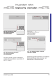
PRINTED CIRCUIT BOARDS
1. The End Station
Power Supply voltage adjustment
If necessary, adjust with care
with battery DISCONNECTED
BATTERY FUSE
1.5 Amp
Protects +ive
battery connection
AC Input
terminals
Output
terminals
BELL/STROBE FUSE
800mA
Protects Hold Off
+ive feed
RS
9
10
11
12
13
14
15
16
Loudspeaker
Volume adjustment
SPEAKER FUSE
800mA
Protects +ive feed
to Speaker
Communicator connectors
NVM
CHIP
Comms
Terminals
AUX FUSE - 800mA
Protects 12v +ive
supply for keypads
iD terminals
Issue 3b
Tamper
switch
1
2
3
4
5
6
7
8
RS.485 connectors
for Engr Keypad,
Printer adaptor and
Gateway (for development)
iD FUSE - 800mA
Protects 12v +ive
detector supply
January 2000
MERiDIAN
48
2. The Keypad
Reverse of
Display
Microprocessor
DO NOT
ADJUST
Tamper
Switch
KEYPAD BLEEPER
VOLUME CONTROL
TERMINALS
P 12V 0V L+ L-
1
3. The iD Output Module
iD Line connections
12v Supply
Address selection jumpers
O
Load
Repeat for OPs 2 and 3
Issue 3b
January 2000
MERiDIAN
49
THE CE MARKING DIRECTIVE
This product complies with the requirements of the EMC Directive
(89/336/EC) and the Low Voltage Directive (73/23/EC and 93/68/EC).
Electromagnetic Compatibility
An alarm installation built around this product will be considered
compliant with the EMC Directive, PROVIDED THAT all other equipment
used carries the 'CE' mark, NAD that the installation follows the guidelines
specified in this manual.
This does NOT guarantee that no compatibility problems will be
experienced, especially with older equipment, not designed to the same
standards. Additionally, exceptional environment scan produce
unpredictable results. Should problems be experienced, the other
equipment should also be checked. Re-siting of the alarm control, or
other equipment, may be the only solution to the problem.
Further information concerning EMC is available in the BSIA publication
"EMC Guidelines for Installers of Security Systems."
Mains Installation
Mains Installation must be performed by a qualified electrician, in
accordance with Electrical Wiring Regulations (BS.7671) - connecting to
the terminals provided with the correct polarity.
A good earth is vital for the current functioning, and EMC performance of
this system.
Issue 3b
January 2000
INSTRUCT-47
Issue 3b
© Castle Care-Tech Ltd.
January 2000