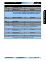
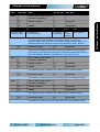
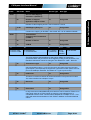
1
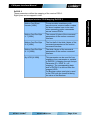
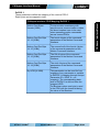
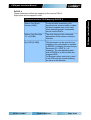
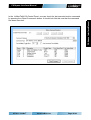
CANopen Interface Manual CANopen Interface Manual CANopen Interface for SG5 and SG7 User Manual This document applies to the following drives: E12x0-xx-xx-xxx (SG5) E14x0-xx-xx-xxx (SG5) C11x0-xx-xx-xxx (SG7) A11x0-xx-xx-xxx (SG7) (with CANopen Interface SW installed) NTI AG / LinMot® www.LinMot.com Page 1/60 CANopen Interface Manual CANopen Interface Manual © 2014 NTI AG This work is protected by copyright. Under the copyright laws, this publication may not be reproduced or transmitted in any form, electronic or mechanical, including photocopying, recording, microfilm, storing in an information retrieval system, not even for didactical use, or translating, in whole or in part, without the prior written consent of NTI AG. LinMot® is a registered trademark of NTI AG. The information in this documentation reflects the stage of development at the time of press and is therefore without obligation. NTI AG reserves itself the right to make changes at any time and without notice to reflect further technical advance or product improvement. Document version 1.91 / mk, May 2014 NTI AG / LinMot® www.LinMot.com Page 2/60 CANopen Interface Manual 1 System overview..............................................................................................................4 2 Connecting the CAN bus.................................................................................................4 2.1 Pin assignment of the CMD Connector (X7, X8)........................................................4 2.2 Pin assignment of the Control Connector (X42, X43)................................................5 2.3 Pin assignment of the Mot / Periph I/O Connector (X44)...........................................5 2.4 CAN Termination.........................................................................................................6 2.4.1 Activating the termination resistor (E12xx/E14xx)...............................................6 2.4.2 Activating the termination resistor (C11xx)..........................................................7 2.4.3 Activating the termination resistor (A11xx)..........................................................7 3 CANopen Parameters......................................................................................................8 4 CANopen Variables........................................................................................................22 5 Mapping of the PDOs.....................................................................................................23 5.1 Default Mapping........................................................................................................23 5.1.1 Default Mapping of the Receive PDOs.............................................................23 5.1.2 Default Mapping of the Transmit PDOs.............................................................24 5.1.3 Default Identifier................................................................................................25 5.2 Using the Motion Command Interface in asynchronous transmission modes.........25 6 Object Dictionary...........................................................................................................26 6.1 Communication Profile Area (1000h - 1FFFh)..........................................................26 6.2 Manufacturer specific Profile Area (2000h – 5FFFh)...............................................34 6.2.1 UPID Commands..............................................................................................34 6.2.2 System Commands...........................................................................................38 6.2.3 Curve Service Commands................................................................................40 6.2.4 Error Log Commands........................................................................................45 6.2.5 Command Table Commands.............................................................................47 7 Examples........................................................................................................................53 7.1 Homing and motion commands................................................................................53 8 Reset Parameters to default values.............................................................................55 9 Configuration of the drive with an EDS File................................................................56 9.1 Configuring a PDO variable by UPID with the EDS file............................................56 9.1.1 Setting the UPIDs of the parameter to map to a PDO......................................56 9.1.2 Getting UPID PDO data into PLC variables......................................................56 9.1.3 Example.............................................................................................................57 10 Interface Error Codes..................................................................................................58 11 Contact Addresses.......................................................................................................60 NTI AG / LinMot® www.LinMot.com Page 3/60 CANopen Interface Manual Table of Contents CANopen Interface Manual 1 System overview – CiA 102 DS V2.0 CAN physical layer for industrial applications – CiA 301 DS V4.0.2 – CANopen application layer and communication profile – CiA 303-3 DR V1.3: CANopen additional specification – Part 3: Indicator specification – CiA 306 DS V1.3: Electronic data sheet specification for CANopen Further information on specifications can be found under: http://www.can-cia.org/ The following resources are available: - 4 TxPDO - 4 RxPDO - 1 TxSDO - 1 RxSDO The supported protocols include: - NMT Error Control (Node Guarding Protocol or Heartbeat Protocol) - PDO (Transmission types 1-240, 250, 253 and 254) - SDO Upload and Download - NMT (Start, Stop, Enter PreOp, Reset Node, Reset Communication) - Boot-Up Message An EDS (Electronic Data Sheet) file is provided for convenient configuration of all CANopen functions of the drive via a PLC. 2 Connecting the CAN bus The CANopen bus can be connected either via X7/8, X42/X43 or X44 depending on the drive type. 2.1 Pin assignment of the CMD Connector (X7, X8) 2 x RJ45 with 1:1 connected signals. Standard twisted pairs: 1/2, 3/6, 4/5, 7/8. Use Ethernet cables according the EIA / TIA 568A standard. NTI AG / LinMot® Pin 1 Pin 2 Pin 3 Pin 4/5 RS485 A RS485 B RS485 Y Ground Pin 6 RS485 Z Pin 7 Pin 8 CAN H CAN L www.LinMot.com Page 4/60 CANopen Interface Manual The LinMot CANopen drives comply with the following specifications: CANopen Interface Manual 2.2 Pin assignment of the Control Connector (X42, X43) Pin 1 Pin 2 Pin 3 Pin 4/5 C Dig IN 1 C Dig IN 2 C Dig IN 3 Ground Pin 6 C Dig OUT 1 Pin 7 Pin 8 CAN H CAN L 2.3 Pin assignment of the Mot / Periph I/O Connector (X44) Molex Micro-Fit 3.0™ (Molex Art.Nr.: 43045-1000) Pin 1 Pin 2 Pin 3 Pin 4 Pin 5 NTI AG / LinMot® DGND MP DIG IN 1 MP DIG IN 2 CANGND CAN H Pin 6 24VDC OUT Pin 7 Pin 8 Pin 9 Pin 10 MP DIG OUT 1 MP DIG IN 3 AnIn CAN L www.LinMot.com Page 5/60 CANopen Interface Manual 2 x RJ45 with 1:1 connected signals. Standard twisted pairs: 1/2, 3/6, 4/5, 7/8. Use Ethernet cables according the EIA / TIA 568A standard. CANopen Interface Manual 2.4 CAN Termination CANopen Interface Manual The CAN-bus must be terminated by two 120 Ohm resistors at both ends of the bus line, according to the following figure: 2.4.1 Activating the termination resistor (E12xx/E14xx) For easy installation, the LinMot CANopen drives has built-in termination resistors, which can be activated, if the LinMot drive is at the end of the bus line, and if there is no termination in the connector. S5 Switch 1: AnIn2 pull-down (4k7Ω Pulldown on X4.4). Set to ON, if X4.4 is used as digital output Switch 2: Termination resistor for RS485 on CMD (120Ω between pin 1 and 2 on X7/X8) on/off Switch 3: CAN termination on CMD (120Ω between pin 7 and 8 on X7/X8) on/off Switch 4: CAN termination on ME (120Ω between pin 7 and 8 on X10/X11) on/off ( Factory setting: all switches “off” ) To activate the built-in termination resistors, switch 3 of S5 has to be set to ON. NTI AG / LinMot® www.LinMot.com Page 6/60 CANopen Interface Manual 2.4.2 Activating the termination resistor (C11xx) S4 Switch 1: RS232 / RS485 select Switch 2: Termination resistor for RS485 on CMD (120Ω between pin 1 and 2 on X7/X8) on/off Switch 3: CAN termination on CMD (120Ω between pin 7 and 8 on X7/X8) on/off Switch 4: Bootstrap ( Factory setting: all switches “off” ) To activate the built-in termination resistors, switch 3 of S4 has to be set to ON. 2.4.3 Activating the termination resistor (A11xx) For easy installation, the LinMot CANopen drives has built-in termination resistors, which can be activated, if the LinMot drive is at the end of the bus line, and if there is no termination in the connector. S5 Switch 1: CAN termination (120Ω between CANL and CANH) on/off Switch 2: Set all drive parameters to default Switch 3: Bootstrap ( Factory setting: all switches “off” ) To activate the built-in termination resistors, switch 1 of S5 has to be set to ON. NTI AG / LinMot® www.LinMot.com Page 7/60 CANopen Interface Manual For easy installation, the LinMot CANopen drives has built-in termination resistors, which can be activated, if the LinMot drive is at the end of the bus line, and if there is no termination in the connector. CANopen Interface Manual The CANopen drives have an additional parameter tree branch, which can be configured with the distributed LinMot-Talk software. With these parameters, the CANopen behaviour can be defined. The LinMot-Talk1100 software can be downloaded from http://www.linmot.com. Depending on the specific drive type used, not all parameters may be present. It is also possible to configure the drive via a PLC by writing to the appropriate CANopen dictionary entries. This has to be done when the drive is in the pre-operational state. If the PLC reconfigures the drive, the changes are not reflected in the parameter section of the LinMot-Talk software. The values sent via the PLC will take precedence over the configuration seen in the LinMot-Talk software! Dis-/Enable With the Dis-/Enable parameter the LinMot drive can be run without the CANopen interface going online. So in a first step the system can be configured and run without any bus connection. CANopen Interface\ Dis-/Enable Disable The drive does not take part in the CANopen communication. Enable The drive takes part in the CANopen communication. NTI AG / LinMot® www.LinMot.com Page 8/60 CANopen Interface Manual 3 CANopen Parameters CANopen Interface Manual Baud Rate In this section the parameters for the baud rate selection are located. CANopen Interface\ Baud Rate \Baud Rate Source Select By Hex Switch S1 CAN bus baud rate dependent on S1: 0 = By BTR 1 = 125 kBit/s 2 = 250 kBit/s 3 = 500 kBit/s 4 = 1 Mbit/s By Parameter The CAN bus baud rate is selected by the “Baudrate Parameter”: - 125 kBit/s [1] - 250 kBit/s [2] - 500 kBit/s [3] - 1 Mbit/s [4] By BTR CAN bus baud rate is defined according to the Bit Timing Register Baud Rate Parameter Definition The baud rate parameter defines the CAN bus baud rate for the CANopen connection. CANopen Interface\ Baud Rate\ Baud Rate Parameter Definition 125 kBit/s CAN bus baud rate = 125 kBit/s 250 kBit/s CAN bus baud rate = 250 kBit/s 500 kBit/s CAN bus baud rate = 500 kBit/s 1 Mbit/s CAN bus baud rate = 1 Mbit/s Advanced Bit Timing Setting For special applications where no standard setting for the baud rate works, this parameter defines the bit timing for the CAN bus. The setting of the baud rate by Bit Timing Register is only necessary on special bus configurations: For example, if there are devices on the bus that have slow optocouplers. NTI AG / LinMot® www.LinMot.com Page 9/60 CANopen Interface Manual Baud Rate Source Select Defines the source of the baud rate definition. CANopen Interface Manual Node-ID In this section the Node-ID can be configured. CANopen Interface\ Node-ID\ Node-ID Source Select By Hex Switch S2 The Node-ID is determined by the hex switch S2. By Hex Switches S1 and S2 The Node-ID is determined by the two hex switches S1 and S2. By Parameter The Node-ID is determined via an additional parameter. Node-ID Parameter Value Used Node-ID, when “By Parameter” is selected as source. The default value is 63 (3Fh). NTI AG / LinMot® www.LinMot.com Page 10/60 CANopen Interface Manual Node-ID Source Select This parameter defines from which source the Node-ID is taken. CANopen Interface Manual PDO Configuration CANopen Interface\ PDO Configuration\ TxPDO 1..4\ TxPDO 1..4 Enable Disable The PDO is deactivated Enable The PDO is activated Transmission Type This defines the transmission type according to DS 301. The default value is 1 (cyclic synchronous). Type 253 (Asynchronous RTR only) and 254 (Asynchronous with inhibit time) are supported as well. The transmission type 250 is LinMot specific (it is reserved according to DS 301). If the transmission type 250 is selected, the transmit PDO is sent immediately after reception of the corresponding receive PDO (TxPDO 1 corresponds to RxPDO 1 and so on). It can be used to realize a simple Poll-Request / Poll-Response type bus structure. No. of SYNC msgs between transmissions Defines how many SYNC messages have to be received before the TxPDO is sent again (this configures transmission types 1-240). Inhibit Time [us] Defines the minimal time between two send events in multiples of 100us. Event Time [ms] Defines the maximal time between two send events in ms. NTI AG / LinMot® www.LinMot.com Page 11/60 CANopen Interface Manual TxPDO 1..4 Enable Selector for enabling/disabling the transmit PDO 1..4. CANopen Interface Manual RxPDO 1..4 Enable Selector for enabling/disabling the receive PDO 1..4. Disable The PDO is deactivated Enable The PDO is activated Transmission Type This defines the transmission type according to DS 301. The default value is cyclic synchronous (transmission types 1-240). Type 254 (Asynchronous with inhibit Time) is supported as well. The transmission type 250 is LinMot specific (its reserved according to DS 301). If the transmission type 250 is selected, the transmit PDO is sent immediately after reception of the corresponding receive PDO (TxPDO 1 corresponds to RxPDO 1 and so on). It can be used to realize a simple Poll-Request / Poll-Response type bus structure. NTI AG / LinMot® www.LinMot.com Page 12/60 CANopen Interface Manual CANopen Interface\ PDO Configuration\ RxPDO 1..4\RxPDO 1..4 Enable CANopen Interface Manual PDO Mapping CANopen Interface\ PDO Mapping\ TxPDO 1 Status Word [16Bit] If this Boolean parameter is set, the status word is transmitted with TxPDO 1. State Var [16Bit] If this Boolean parameter is set, the state var (high byte = state / low byte = sub state) is transmitted with TxPDO 1. Actual Position [32Bit] If this Boolean parameter is set, the 32bit actual position is transmitted with TxPDO 1. By UPID [8-32Bit] This parameter can be used for free mapping of any parameter or variable to TxPDO 1 (mapping through Unique Parameter ID = UPID, 0 = no mapping). The corresponding data size in TxPDO 1 is derived from the mapped UPID. For Boolean values one byte is used in the PDO with the lowest bit being the value of the Boolean. NTI AG / LinMot® www.LinMot.com Page 13/60 CANopen Interface Manual TxPDO 1 These parameters define the mapping of the transmit PDO 1. Eight bytes can be mapped in total. CANopen Interface Manual TxPDO 2 These parameters define the mapping of the transmit PDO 2. Eight bytes can be mapped in total. Demand Position [32Bit] If this Boolean parameter is set, the 32-bit demand position is transmitted with TxPDO 2. Demand Current [32Bit] If this Boolean parameter is set, the 32-bit demand current value (= motor current) is transmitted with TxPDO 2. By UPID [8-32Bit] This parameter can be used for free mapping of any parameter or variable to TxPDO 2 (mapping through Unique Parameter ID = UPID, 0 = no mapping). The corresponding data size in TxPDO 2 is derived from the mapped UPID. For Boolean values one byte is used in the PDO with the lowest bit being the value of the Boolean. NTI AG / LinMot® www.LinMot.com Page 14/60 CANopen Interface Manual CANopen Interface\ PDO Mapping\ TxPDO 2 CANopen Interface Manual TxPDO 3 These parameters define the mapping of the transmit PDO 3. Eight bytes can be mapped in total. Warn Word [16Bit] If this Boolean parameter is set, the warn word (= bit coded warnings) is transmitted with TxPDO 1. Logged Error Code [16Bit] If this Boolean parameter is set, the logged error code is transmitted with TxPDO 1. Motion Cmd Status [16Bit] Feedback of the motion command header (toggle, etc..) By UPID [8-32Bit] This parameter can be used for free mapping of any parameter or variable to TxPDO 3 (mapping through Unique Parameter ID = UPID, 0 = no mapping). The corresponding data size in TxPDO 3 is derived from the mapped UPID. For Boolean values one byte is used in the PDO with the lowest bit being the value of the Boolean. TxPDO 4 These parameters define the mapping of the transmit PDO 4. Eight bytes can be mapped in total. CANopen Interface\ PDO Mapping\ TxPDO 4 By UPID [8-32Bit] NTI AG / LinMot® This parameter can be used for free mapping of any parameter or variable to TxPDO 4 (mapping through Unique Parameter ID = UPID, 0 = no mapping). The corresponding data size in TxPDO 4 is derived from the mapped UPID. For Boolean values one byte is used in the PDO with the lowest bit being the value of the Boolean. www.LinMot.com Page 15/60 CANopen Interface Manual CANopen Interface\ PDO Mapping\ TxPDO 3 CANopen Interface Manual RxPDO 1 These parameters define the mapping of the receive PDO 1. Eight bytes can be mapped in total. Control Word [16Bit] If this Boolean parameter is set, the control word has to be transmitted with RxPDO 1. Motion Cmd Header [16Bit] Motion command interface header. Motion Cmd Par Byte 0..3 [32Bit] The first 4 bytes of the command parameters of the motion command interface. By UPID [8-32Bit] This parameter can be used for free mapping of any parameter or variable to RxPDO 1 (mapping through Unique Parameter ID = UPID, 0 = no mapping). The corresponding data size in RxPDO 1 is derived from the mapped UPID. For Boolean values one byte is used in the PDO with the lowest bit being the value of the Boolean. NTI AG / LinMot® www.LinMot.com Page 16/60 CANopen Interface Manual CANopen Interface\ PDO Mapping\ RxPDO 1 CANopen Interface Manual RxPDO 2 These parameters define the mapping of the receive PDO 2. Eight bytes can be mapped in total. Motion Cmd Slave Header [16Bit] To ensure data consistency with asynchronous communication modes, the slave headers have to be used when spreading motion commands across several PDOs. Motion Cmd Par Byte 4..7 [32Bit] The second 4 bytes of the command parameters of the motion command interface. Motion Cmd Par Byte 8..9 [16Bit] The first half of the third 4 bytes of the command parameters of the motion command interface. Motion Cmd Par Byte 8..11 [32Bit] The third 4 bytes of the command parameters of the motion command interface. By UPID [8-32Bit] This parameter can be used for free mapping of any parameter or variable to RxPDO 2 (mapping through Unique Parameter ID = UPID, 0 = no mapping). The corresponding data size in RxPDO 2 is derived from the mapped UPID. For Boolean values one byte is used in the PDO with the lowest bit being the value of the Boolean. NTI AG / LinMot® www.LinMot.com Page 17/60 CANopen Interface Manual CANopen Interface\ PDO Mapping\ RxPDO 2 CANopen Interface Manual RxPDO 3 These parameters define the mapping of the receive PDO 3. Eight bytes can be mapped in total. Motion Cmd Slave Header [16Bit] To ensure data consistency with asynchronous communication modes, the slave headers have to be used when spreading motion commands across several PDOs. Motion Cmd Par Byte 10..13 [32Bit] The fourth 4 bytes of the command parameters of the Motion Command Interface. Motion Cmd Par Byte 14..15 [16Bit] The second half of the fourth 4 bytes of the command parameters of the Motion Command Interface. Motion Cmd Par Byte 12..15 [32Bit] The fifth 4 bytes of the command parameters of the Motion Command Interface. Motion Cmd Par Byte 16..19 [32Bit] The sixth 4 bytes of the command parameters of the Motion Command Interface. By UPID [8-32Bit] This parameter can be used for free mapping of any parameter or variable to RxPDO 3 (mapping through Unique Parameter ID = UPID, 0 = no mapping). The corresponding data size in RxPDO 3 is derived from the mapped UPID. For Boolean values one byte is used in the PDO with the lowest bit being the value of the Boolean. NTI AG / LinMot® www.LinMot.com Page 18/60 CANopen Interface Manual CANopen Interface\ PDO Mapping\ RxPDO 3 CANopen Interface Manual RxPDO 4 These parameters define the mapping of the receive PDO 4. Eight bytes can be mapped in total. Motion Cmd Slave Header [16Bit] To ensure data consistency with asynchronous communication modes, the slave headers have to be used when spreading motion commands across several PDOs. Motion Cmd Par Byte 16..19 [32Bit] The sixth 4 bytes of the command parameters of the motion command interface. By UPID [8-32Bit] This parameter can be used for free mapping of any parameter or variable to RxPDO 4 (mapping through Unique Parameter ID = UPID, 0 = no mapping). The corresponding data size in RxPDO 4 is derived from the mapped UPID. For Boolean values one byte is used in the PDO with the lowest bit being the value of the Boolean. NTI AG / LinMot® www.LinMot.com Page 19/60 CANopen Interface Manual CANopen Interface\ PDO Mapping\ RxPDO 4 CANopen Interface Manual The heartbeat mechanism takes precedence over the node guarding protocol. If object 1017h of the object dictionary (Producer Heartbeat Time) is different from zero, the heartbeat protocol is used. If this entry is zero and the guard time multiplied with the life time factor is not zero, the node guarding protocol is used instead. If all of these values are zero, no error control mechanism will be active. The drive is also capable of consuming a heartbeat. If object 1016h sub 1 of the object dictionary (Consumer Heartbeat Time 1) is different from zero, a heartbeat is consumed with the node-ID and time (given in ms) taken from this entry. Node Guarding Protocol Directory for configuring the node guarding protocol. CANopen Interface\ NMT Error Control\ Node Guarding Protocol Guard Time The guard time in ms, when the node guarding mechanism is active. Life Time Factor Multiplier used with the Guard Time. The total time that has to pass for a node to trigger a failure is called the node life time. The node life time is the guard time multiplied by the life time factor. Node Guarding starts with the reception of the first guarding message. Heartbeat Protocol These parameters configure the heartbeat protocol. CANopen Interface\ NMT Error Control\ Heartbeat Protocol Producer Time Cycle time for producing a heartbeat in ms. Consumer Time Time for the consumed heartbeat in ms. Consumed Node-ID (Master) Node-ID of the master, who's heartbeat is monitored. NTI AG / LinMot® www.LinMot.com Page 20/60 CANopen Interface Manual NMT Error Control CANopen Interface Manual These parameters configure the legacy watchdog of the sync telegram. This can be used together with heartbeat or node guarding. This feature is not part of the DS 301 specifications and is LinMot specific. The time between the arrival of two sync telegrams is measured. If the measured time exceeds 1.5 * LSW monitored cycle time an error is generated. The Legacy Sync Watchdog is only active while the NMT-State of the drive is operational. Monitoring via the LSW starts automatically on the transition from Pre-Operational to Operational state. Watchdog Enable Enabling/Disabling the legacy sync watchdog feature. CANopen Interface\ NMT Error Control\ Legacy Sync Watchdog\ LSW Enable Disable The sync watchdog is deactivated. Enable The sync watchdog is activated. LSW monitored Cycle Time The real expected sync cycle time can be configured here. NTI AG / LinMot® www.LinMot.com Page 21/60 CANopen Interface Manual Legacy Sync Watchdog CANopen Interface Manual 4 CANopen Variables These variables show information about the status of the CANopen communication: CANopen NMT State Shows the NMT state of the drives. (INITIALISING, STOPPED, PREOPERATIONAL, OPERATIONAL) Node-ID Active node-ID of the drive. Baud Rate Active baud rate of the drive. Active Error Control Protocol Shows if a guarding protocol is active. (None, Heartbeat Protocol, Node Guarding Protocol) SyncCycle Time in [us] between the reception of two SYNC messages. CAN Bit Timing Value of the CAN Bit Timing Register. CANopen: Object Dictionary All supported object dictionary entries can be read here. NTI AG / LinMot® www.LinMot.com Page 22/60 CANopen Interface Manual CANopen CANopen Interface Manual 5 Mapping of the PDOs CANopen Interface Manual 5.1 Default Mapping The PDOs are mapped by default according to the following scheme: 5.1.1 Default Mapping of the Receive PDOs RxPDO 1 Control Word [16Bit] Motion Cmd Header [16Bit] Motion Cmd Par Byte 00..03 [32Bit] RxPDO 2 Length Motion Cmd Par Byte 04..07 [32Bit] Motion Cmd Par Byte 08..11 [32Bit] RxPDO 3 Length Motion Cmd Par Byte 12..15 [32Bit] Motion Cmd Par Byte 16..19 [32Bit] RxPDO 4 A maximum of 4 parameters with a total maximum length of 64 Bit can be mapped by UPID NTI AG / LinMot® Length www.LinMot.com Length [64Bit] Page 23/60 CANopen Interface Manual TxPDO 1 Length Status Word [16Bit] State Var [16Bit] Actual Position [32Bit] TxPDO 2 CANopen Interface Manual 5.1.2 Default Mapping of the Transmit PDOs Length Demand Position [32Bit] Demand Current [32Bit] TxPDO 3 Length Warn Word [16Bit] Logged Error Code [16Bit] A maximum of 4 parameters with a total maximum length of 32 Bit can be mapped by UPID [32Bit] TxPDO 4 Length A maximum of 4 parameters with a total maximum length of 64 Bit can be mapped by UPID [64Bit] If the application requires it, the mapping can be completely changed by the PDO Mapping parameter settings. Many applications do not require to use all resources. NTI AG / LinMot® www.LinMot.com Page 24/60 CANopen Interface Manual 5.1.3 Default Identifier 10 9 8 7 Function Code 6 5 4 3 2 1 0 Node ID This results in the following table: Object Function Code (binary) COB ID (hex) COB ID (dec) Object for Comm. Parameter / Mapping NMT 0000b 00h 0 - SYNC 0001b 80h 128 1005h / 1006h / 1007h Emergency 0001b 81h – FFh 129-255 1014h TxPDO 1 0011b 181h – 1FFh 385-511 1800h / 1A00h TxPDO 2 0101b 281h – 2FFh 513-639 1801h / 1A01h TxPDO 3 0111b 381h – 3FFh 641-767 1802h / 1A02h TxPDO 4 1001b 481h – 4FFh 769-895 1803h / 1A03h RxPDO 1 0100b 201h – 27Fh 897-1023 1400h / 1600h RxPDO 2 0110b 301h – 37Fh 1025-1151 1401h / 1601h RxPDO 3 1000b 401h – 47Fh 1153-1279 1402h / 1602h RxPDO 4 1010b 501h – 57Fh 1281-1407 1403h / 1603h TxSDO 1011b 581h – 5FFh 1409-1535 - RxSDO 1100b 601h – 67Fh 1537-1663 - NMT Error Control (NodeGuarding, Heartbeat) 1110b 701h – 77Fh 1793-1919 100Ch / 100Dh (NG) 1016h / 1017h (Heartbeat) 5.2 Using the Motion Command Interface in asynchronous transmission modes Because the CMD interface of the LinMot drives consists of more than 8 bytes, it is necessary to link two or more RxPDOs together to ensure data consistency. This is done by the “Motion CMD Slave Header”. In order to execute a command, the toggle bits of all headers have to be changed to the same new value. On the slave header only the last 4 bits are evaluated, so it is possible to simply copy the “CMD Header” from RxPDO 1 to the “Motion CMD Slave Header” of RxPDOs 2-4. NTI AG / LinMot® www.LinMot.com Page 25/60 CANopen Interface Manual The default identifiers (11 bit identifier) are allocated by the following scheme: CANopen Interface Manual 6 Object Dictionary 6.1 Communication Profile Area (1000h - 1FFFh) Index Sub-Index Name Access Type Data Type 1000h - Device Type ro Unsigned32 Always zero (= no standardized device profile). 1001h - Error register ro Unsigned8 Only bit 0 is supported, which indicates a generic error. 1005h - COB-ID SYNC rw Unsigned32 Defines the COB-ID of the Synchronization Object (SYNC). 1006h - Communication cycle period rw Unsigned32 This object defines the communication cycle period in μs. This period defines the SYNC interval. It is 0 if not used. The object is only relevant for SYNC producers and is not used in CANopen slaves. 1007h - Synchronous window length rw Unsigned32 Contains the length of the time window for synchronous PDOs in μs. It is 0 if not used. This parameter is for compatibility only, it is not used in the LinMot drive. 1008h - Manufacturer Device Name const String Contains the Device Name (including HW Revision) as an ASCII string. 1009h - Manufacturer HW Version const String Contains the Device Serial Number as an ASCII string. 100Ah - Manufacturer SW Version const String Contains the version of the installed firmware as an ASCII string. 100Ch - Guard Time rw Unsigned16 Contains the Guard Time used in the node guarding protocol. 100Dh - Life Time Factor rw Unsigned8 Contains the Life Time Factor used in the node guarding protocol. 1014h - COB-ID Emergency Object rw Unsigned32 Defines the COB-ID of the emergency object (EMCY). NTI AG / LinMot® www.LinMot.com Page 26/60 CANopen Interface Manual In this chapter all entries in the object dictionary, which are supported by the drives, are listed. Index Sub-Index Name Access Type Data Type 1016h - Consumer heartbeat time - - 0h Number of Entries ro Unsigned8 1h Consumer heartbeat time 1 rw Unsigned32 The consumer heartbeat time defines the expected heartbeat cycle time and thus has to be higher than the corresponding producer heartbeat time configured on the device producing this heartbeat. Monitoring starts after the reception of the first heartbeat. If the consumer heartbeat time is 0 the corresponding entry is not used. The time has to be a multiple of 1ms. 1017h - Producer heartbeat time rw Unsigned16 The producer heartbeat time defines the cycle time of the heartbeat. If not used it is to be set to 0. The time has to be a multiple of 1ms. 1018h - Identity Object - - 0h Number of Entries ro Unsigned8 1h Vendor ID ro Unsigned32 The vendor ID contains a unique value allocated to each manufacturer of CANopen devices. The vendor ID of LinMot is 0000 0156h. 2h Product Code ro Unsigned32 ro Unsigned32 ro Unsigned32 Contains the drive type. 3h Revision Number Contains the drive version. 4h Serial Number Contains the last four ASCII characters of the serial number. NTI AG / LinMot® www.LinMot.com Page 27/60 CANopen Interface Manual CANopen Interface Manual Index Sub-Index Name Access Type Data Type 1400h - Receive PDO Communication Parameter 0 (RxPDO 1) - - 0h Number of Entries ro Unsigned8 1h COB-ID ro Unsigned32 31 30 29 28-11 10-0 0: PDO is valid 1: PDO is invalid 0: RTR allowed 1: no RTR allowed 0: (11-bit ID) 1: (29-bit ID) All 0 if 11-bit identifier 11-bit identifier The PDO valid/not valid bit allows to select which PDOs are used in the operational state. Only this bit can be changed by writing to this parameter. The identifiers themselves cannot be changed. The default ID is 200h + Node-ID. 2h Transmission type rw Unsigned8 Only transmission types 1 (cyclic synchronous), 254 (asynchronous) and 250 (poll-request / poll-response) are supported. Type 250 is LinMot specific and not part of the CANopen standard. The Default is 1 (cyclic synchronous). 1401h - Receive PDO Communication Parameter 1 (RxPDO 2) - - 0h Number of Entries ro Unsigned8 1h COB-ID ro Unsigned32 The default ID is 300h + Node-ID. See 1400h sub 1h for additional details. 2h Transmission type rw Unsigned8 The default is 1 (cyclic synchronous). See 1400h sub 2h for additional details. 1402h - Receive PDO Communication Parameter 2 (RxPDO 3) - - 0h Number of Entries ro Unsigned8 1h COB-ID ro Unsigned32 The default ID is 400h + Node-ID. See 1400h sub 1h for additional details. 2h Transmission type rw Unsigned8 The default is 1 (cyclic synchronous). See 1400h sub 2h for additional details. NTI AG / LinMot® www.LinMot.com Page 28/60 CANopen Interface Manual CANopen Interface Manual Index Sub-Index Name Access Type Data Type 1403h - Receive PDO Communication Parameter 3 (RxPDO 4) - - 0h Number of Entries ro Unsigned8 1h COB-ID ro Unsigned32 The default ID is 500h + Node-ID. See 1400h sub 1h for additional details. 2h Transmission type rw Unsigned8 The default is 1 (cyclic synchronous). See 1400h sub 2h for additional details. 1600h - Receive PDO Mapping Parameter 0 (RxPDO 1) - - 0h Number of mapped application objects in PDO rw Unsigned8 Number of valid mapping entries. Can be between 0 and 8. 1h-8h PDO Mapping Entry 1-8 rw Unsigned32 Contains the mapping for RxPDO 1. A mapping entry is built as follows: 16-31 8-15 0-7 index sub-index Object length 1601h - Receive PDO Mapping Parameter 1 (RxPDO 2) - - 0h Number of mapped application objects in PDO rw Unsigned8 Number of valid mapping entries. Can be between 0 and 8. 1h-8h PDO Mapping Entry 1-8 rw Unsigned32 Contains the mapping for RxPDO 2 See 1600h sub 1-8h for additional details. 1602h - Receive PDO Mapping Parameter 2 (RxPDO 3) - - 0h Number of mapped application objects in PDO rw Unsigned8 Number of valid mapping entries. Can be between 0 and 8. 1h-8h PDO Mapping Entry 1-8 rw Unsigned32 Contains the mapping for RxPDO 3 See 1600h sub 1-8h for additional details. NTI AG / LinMot® www.LinMot.com Page 29/60 CANopen Interface Manual CANopen Interface Manual Index Sub-Index Name Access Type Data Type 1603h - Receive PDO Mapping Parameter 3 (RxPDO 4) - - 0h Number of mapped application objects in PDO rw Unsigned8 Number of valid mapping entries. Can be between 0 and 8. 1h-8h PDO Mapping Entry 1-8 rw Unsigned32 Contains the mapping for RxPDO 4 See 1600h sub 1-8h for additional details. 1800h - Transmit PDO Communication Parameter 0 (TxPDO 1) - - 0h Number of Entries ro Unsigned8 1h COB-ID ro Unsigned32 31 30 29 28-11 10-0 0: PDO is valid 1: PDO is invalid 0: RTR allowed 1: no RTR allowed 0: (11-bit ID) 1: (29-bit ID) All 0's if 11-bit identifier 11-bit identifier The PDO valid/not valid bit allows to select which PDOs are used in the operational state. Only this bit can be changed by writing to this parameter. The identifiers themselves cannot be changed. The default ID is 180h + Node-ID. 2h Transmission type rw Unsigned8 Only transmission types 1 (cyclic synchronous), 254 (asynchronous) and 250 (poll-request / poll-response) are supported. Type 250 is LinMot specific and not part of the CANopen standard. The Default is 1 (cyclic synchronous). 3h Inhibit time rw Unsigned16 This time is a minimum interval for PDO transmission in asynchronous modes. The value is defined as multiple of 100μs. 4h Reserved rw Unsigned8 5h Event timer rw Unsigned16 In asynchronous modes additionally an event time can be used for TPDOs. If an event timer exists for a TPDO (value not equal to 0) the elapsed timer is considered to be an event. The event timer elapses as a multiple of 1 ms . This event will cause the transmission of this TPDO in addition to otherwise defined events. NTI AG / LinMot® www.LinMot.com Page 30/60 CANopen Interface Manual CANopen Interface Manual Index Sub-Index Name Access Type Data Type 1801h - Transmit PDO Communication Parameter 1 (TxPDO 2) - - 0h Number of Entries ro Unsigned8 1h COB-ID ro Unsigned32 The default ID is 280h + Node-ID. See 1800h sub 1h for additional details. 2h Transmission type rw Unsigned8 The default is 1 (cyclic synchronous). See 1800h sub 2h for additional details. 3h Inhibit time rw Unsigned16 See 1800h sub 3h for additional details. 4h Reserved rw Unsigned8 rw Unsigned16 5h Event timer See 1800h sub 5h for additional details. 1802h - Transmit PDO Communication Parameter 2 (TxPDO 3) - - 0h Number of Entries ro Unsigned8 1h COB-ID ro Unsigned32 The default ID is 380h + Node-ID. See 1800h sub 1h for additional details. 2h Transmission type rw Unsigned8 The default is 1 (cyclic synchronous). See 1800h sub 2h for additional details. 3h Inhibit time rw Unsigned16 See 1800h sub 3h for additional details. 4h Reserved rw Unsigned8 rw Unsigned16 5h Event timer See 1800h sub 5h for additional details. NTI AG / LinMot® www.LinMot.com Page 31/60 CANopen Interface Manual CANopen Interface Manual Index Sub-Index Name Access Type Data Type 1803h - Transmit PDO Communication Parameter 3 (TxPDO 4) - - 0h Number of Entries ro Unsigned8 1h COB-ID ro Unsigned32 The default ID is 480h + Node-ID. See 1800h sub 1h for additional details. 2h Transmission type rw Unsigned8 The default is 1 (cyclic synchronous). See 1800h sub 2h for additional details. 3h Inhibit time rw Unsigned16 See 1800h sub 3h for additional details. 4h Reserved rw Unsigned8 rw Unsigned16 5h Event timer See 1800h sub 5h for additional details. 1A00h - Transmit PDO Mapping Parameter 0 (TxPDO 1) - - 0h Number of mapped application objects in PDO rw Unsigned8 Number of valid mapping entries. Can be between 0 and 8. 1h-8h PDO Mapping Entry 1-8 rw Unsigned32 Contains the mapping for TxPDO 1 See 1600h sub 1-8h for additional details. 1A01h - Transmit PDO Mapping Parameter 1 (TxPDO 2) - - 0h Number of mapped application objects in PDO rw Unsigned8 Number of valid mapping entries. Can be between 0 and 8. 1h-8h PDO Mapping Entry 1-8 rw Unsigned32 Contains the mapping for TxPDO 2 See 1600h sub 1-8h for additional details. NTI AG / LinMot® www.LinMot.com Page 32/60 CANopen Interface Manual CANopen Interface Manual Index Sub-Index Name Access Type Data Type 1A02h - Transmit PDO Mapping Parameter 2 (TxPDO 3) - - 0h Number of mapped application objects in PDO rw Unsigned8 Number of valid mapping entries. Can be between 0 and 8. 1h-8h PDO Mapping Entry 1-8 rw Unsigned32 Contains the mapping for TxPDO 3 See 1600h sub 1-8h for additional details. 1A03h - Transmit PDO Mapping Parameter 3 (TxPDO 4) - - 0h Number of mapped application objects in PDO rw Unsigned8 Number of valid mapping entries. Can be between 0 and 8. 1h-8h PDO Mapping Entry 1-8 rw Unsigned32 Contains the mapping for TxPDO 4 See 1600h sub 1-8h for additional details. NTI AG / LinMot® www.LinMot.com Page 33/60 CANopen Interface Manual CANopen Interface Manual CANopen Interface Manual 6.2 Manufacturer specific Profile Area (2000h – 5FFFh) Parameters can be modified via their UPIDs (Unique Parameter ID) via CANopen. To use a UPID command, an SDO read or write has to be performed on the index “2000h + UPID”. The sub-index specifies the command which is performed. Index Sub-Index Description Access Type Data Type 2000h + UPID 01h RAM Value rw Bool - Unsigned32 Read / Write the RAM Value of a UPID. Any UPID from a Boolean type up to an unsigned32 type can be read or written. Read RAM Value by UPID COB-ID 600 + Node-ID, SDO Read from PLC to LinMot Drive: Data Byte SDO CS 40h 01 (LSB) Index yyh 02 yyh 03 Sub-Index 01h 04 05 06 07 08 (MSB) yy yy: 2000h + UPID Write RAM Value by UPID COB-ID 600 + Node-ID, SDO Write from PLC to LinMot Drive: Data Byte SDO CS 23h 01 (LSB) Index yyh 02 yyh 03 Sub-Index 01h 04 Data xxh 05 Data xxh 06 xxh 07 xxh 08 (MSB) yy yy: 2000h + UPID xx xx xx xx: Value to write (size depends on the UPID that will be written) NTI AG / LinMot® www.LinMot.com Page 34/60 CANopen Interface Manual 6.2.1 UPID Commands Index Sub-Index Description Access Type Data Type 2000h + UPID 02h ROM Value rw Bool - Unsigned32 Read / Write the ROM Value of a UPID. Any UPID from a Boolean type up to an unsigned32 type can be read or written. If a value in the ROM is changed, it is not immediately reflected in the RAM. Values are read from the ROM to the RAM on startup of the drive. Use the “RAM/ROM Write” command (sub-index 06h) to change both values at the same time. Read ROM Value by UPID COB-ID 600 + Node-ID, SDO Read from PLC to LinMot Drive: Data Byte SDO CS 40h 01 (LSB) Index yyh 02 yyh 03 Sub-Index 02h 04 05 06 07 08 (MSB) yy yy: 2000h + UPID Write ROM Value by UPID COB-ID 600 + Node-ID, SDO Write from PLC to LinMot Drive: Data Byte SDO CS 23h 01 (LSB) Index yyh 02 yyh 03 Sub-Index 02h 04 Data xxh 05 Data xxh 06 xxh 07 xxh 08 (MSB) yy yy: 2000h + UPID xx xx xx xx: Value to write (size depends on the UPID that will be written) Index Sub-Index Description Access Type Data Type 2000h + UPID 03h Min Value ro Bool - Unsigned32 The minimal possible value of the UPID is returned. Read Min Value by UPID COB-ID 600 + Node-ID, SDO Read from PLC to LinMot Drive: Data Byte SDO CS 40h 01 (LSB) Index yyh 02 yyh 03 Sub-Index 03h 04 05 06 07 08 (MSB) yy yy: 2000h + UPID NTI AG / LinMot® www.LinMot.com Page 35/60 CANopen Interface Manual CANopen Interface Manual CANopen Interface Manual Index Sub-Index Description Access Type Data Type 2000h + UPID 04h Max Value ro Bool - Unsigned32 Read Max Value by UPID COB-ID 600 + Node-ID, SDO Read from PLC to LinMot Drive: Data Byte SDO CS 40h 01 (LSB) Index yyh 02 Sub-Index 04h 04 yyh 03 05 06 07 08 (MSB) yy yy: 2000h + UPID Index Sub-Index Description Access Type Data Type 2000h + UPID 05h Default Value ro Bool - Unsigned32 The default value of the UPID is returned. Read Default Value by UPID COB-ID 600 + Node-ID, SDO Read from PLC to LinMot Drive: Data Byte SDO CS 40h 01 (LSB) Index yyh 02 Sub-Index 05h 04 yyh 03 05 06 07 08 (MSB) yy yy: 2000h + UPID Index Sub-Index Description Access Type Data Type 2000h + UPID 06h RAM/ROM Write wo Bool - Unsigned32 Write the RAM and ROM Value of a UPID. Any UPID from a Boolean type up to an unsigned32 type can be written. Write RAM/ROM Value by UPID COB-ID 600 + Node-ID, SDO Write from PLC to LinMot Drive: Data Byte SDO CS 23h 01 (LSB) Index yyh 02 yyh 03 Sub-Index 06h 04 Data xxh 05 Data xxh 06 xxh 07 xxh 08 (MSB) yy yy: 2000h + UPID xx xx xx xx: Value to write (size depends on the UPID that will be written) NTI AG / LinMot® www.LinMot.com Page 36/60 CANopen Interface Manual The maximal possible value of the UPID is returned. Index Sub-Index Description Access Type Data Type 2000h 20h Start Getting UPID List wo Unsigned16 With this command, the starting UPID can be set from which the command “Get Next UPID List item” begins returning info when called. This command has to be sent at least once before information on UPIDs can be retrieved via the “Get Next UPID List item” command. Start getting UPID List COB-ID 600 + Node-ID, SDO Write from PLC to LinMot Drive: Data Byte SDO CS 23h 01 (LSB) Index yyh 02 Sub-Index 20h 04 yyh 03 Data xxh 05 Data xxh 06 xxh 07 xxh 08 (MSB) xx xx xx xx: Any Data yy yy: 2000h + UPID Index Sub-Index Description Access Type Data Type 2000h 21h Get Next UPID List item ro Unsigned32 With this command information on UPIDs can be read. After the initialization with the command “Start getting UPID List”, information on UIPIDs can be read with this command. The command can be repeatedly issued. With each new command, the information on the next existing UPID is sent. When the end of the list is reached, the UPID FFFFh is sent. Get Next UPID List item COB-ID 600 + Node-ID, SDO Read from PLC to LinMot Drive: Data Byte SDO CS 40h 01 (LSB) Index yyh 02 Sub-Index 21h 04 yyh 03 05 06 07 08 (MSB) yy yy: 2000h + UPID Return Value COB-ID 580 + Node-ID, Response from LinMot Drive to PLC: Data Byte SDO CS 42h 01 (LSB) Index yyh 02 Sub-Index 21h 04 yyh 03 Address Usage yyh yyh 05 06 UPID found xxh xxh 07 08 (MSB yy yy: Address Usage xx xx: UPID which was found Address Usage is interpreted as follows: 5 6 7 8 9 www.LinMot.com 10 11 12 This Parameter is used for security Features. 4 Paramteter is included when calculating the hash table. 3 Live Parameter NTI AG / LinMot® 2 ROM Write allowed 0 1 (LSB) ROM Read allowed RAM Write allowed RAM Read allowed Bit Nr.: 13 14 15 (MSB) Page 37/60 CANopen Interface Manual CANopen Interface Manual Index Sub-Index Description Access Type Data Type 2000h 22h Start Getting Modified UPID List wo Unsigned16 This command is used in the same way as the “Start Getting UPID List” command (2000h sub 20h). Only UPIDs with values that differ from their default values are returned. Index Sub-Index Description Access Type Data Type 2000h 23h Get Next Modified UPID List item ro Unsigned32 This command is used the in same way as the “Get Next UPID List item” command (2000h sub 21h). Only UPIDs with values that differ from their default values are returned. 6.2.2 System Commands Index Sub-Index Description Access Type Data Type 2000h 07h Set ROM to default (OS) wo Unsigned8 - Unsigned32 Set all parameters of the OS to default values. The execution of this command can take several seconds. Any data can be written for the command to be executed. Set ROM to default (OS) COB-ID 600 + Node-ID, SDO Write from PLC to LinMot Drive: Data Byte SDO CS 23h 01 (LSB) Index 00h 02 Sub-Index 07h 04 20h 03 Data xxh 05 xxh 06 xxh 07 xxh 08 (MSB) xx xx xx xx: Any Data Index Sub-Index Description Access Type Data Type 2000h 08h Set ROM to default (MC SW) wo Unsigned8 - Unsigned32 Set all parameters of the MC SW to default values. he execution of this command can take several seconds. Any data can be written for the command to be executed. Set ROM to default (MC SW) COB-ID 600 + Node-ID, SDO Write from PLC to LinMot Drive: Data Byte SDO CS 23h 01 (LSB) Index 00h 02 20h 03 Sub-Index 08h 04 Data xxh 05 xxh 06 xxh 07 xxh 08 (MSB) xx xx xx xx: Any Data NTI AG / LinMot® www.LinMot.com Page 38/60 CANopen Interface Manual CANopen Interface Manual Index Sub-Index Description Access Type Data Type 2000h 09h Set ROM to default (Interface) wo Unsigned8 - Unsigned32 Set all parameters of the Interface to default values. he execution of this command can take several seconds. Any data can be written for the command to be executed. Set ROM to default (Interface) COB-ID 600 + Node-ID, SDO Write from PLC to LinMot Drive: Data Byte SDO CS 23h 01 (LSB) Index 00h 02 Sub-Index 09h 04 20h 03 Data xxh 05 xxh 06 xxh 07 xxh 08 (MSB) xx xx xx xx: Any Data Index Sub-Index Description Access Type Data Type 2000h 0Ah Set ROM to default (Application) wo Unsigned8 - Unsigned32 Set all parameters of the Application to default values. he execution of this command can take several seconds. Any data can be written for the command to be executed. Set ROM to default (Application) COB-ID 600 + Node-ID, SDO Write from PLC to LinMot Drive: Data Byte SDO CS 23h 01 (LSB) Index 00h 02 20h 03 Sub-Index 0Ah 04 Data xxh 05 xxh 06 xxh 07 xxh 08 (MSB) xx xx xx xx: Any Data Index Sub-Index Description Access Type Data Type 2000h 0Bh Reset Drive wo Unsigned8 - Unsigned32 Initiates a software reset of the drive. Any data can be written for the command to be executed. Reset Drive COB-ID 600 + Node-ID, SDO Write from PLC to LinMot Drive: Data Byte SDO CS 23h 01 (LSB) Index 00h 02 20h 03 Sub-Index 0Bh 04 Data xxh 05 xxh 06 xxh 07 xxh 08 (MSB) xx xx xx xx: Any Data NTI AG / LinMot® www.LinMot.com Page 39/60 CANopen Interface Manual CANopen Interface Manual CANopen Interface Manual Index Sub-Index Description Access Type Data Type 2000h 35h Stop MC and APPL Software wo Unsigned8 - Unsigned32 Stop MC and APPL Software COB-ID 600 + Node-ID, SDO Write from PLC to LinMot Drive: Data Byte SDO CS 23h 01 (LSB) Index 00h 02 20h 03 Sub-Index 35h 04 Data xxh 05 xxh 06 xxh 07 xxh 08 (MSB xx xx xx xx: Any Data Index Sub-Index Description Access Type Data Type 2000h 36h Start MC and APPL Software wo Unsigned8 - Unsigned32 MC SW and Application SW are started. Any data can be written for the command to be executed. Start MC and APPL Software COB-ID 600 + Node-ID, SDO Write from PLC to LinMot Drive: Data Byte SDO CS 23h 01 (LSB) Index 00h 02 20h 03 Sub-Index 36h 04 Data xxh 05 xxh 06 xxh 07 xxh 08 (MSB) xx xx xx xx: Any Data 6.2.3 Curve Service Commands See the “LinMot 1100 Drive Configuration over Fieldbus Interfaces” for additional detail on the use of curve commands and a description of the content of the curve info and data blocks. Index Sub-Index Description Access Type Data Type 2000h 40h Curve Service: Save to Flash (only available on SG5) wo Unsigned8 - Unsigned32 All curves are saved from the RAM to the flash and are thus permanently saved. MC SW and application have to be stopped in order for this command to work (see command 2000h sub 35: Stop MC and Application Software). Any data can be written for the command to be executed. Curve Service: Save to Flash COB-ID 600 + Node-ID, SDO Write from PLC to LinMot Drive: Data Byte SDO CS 23h 01 (LSB) Index 00h 02 20h 03 Sub-Index 40h 04 Data xxh 05 xxh 06 xxh 07 xxh 08 (MSB) xx xx xx xx: Any Data NTI AG / LinMot® www.LinMot.com Page 40/60 CANopen Interface Manual MC SW and Application SW are stopped. Any data can be written for the command to be executed. Index Sub-Index Description Access Type Data Type 2000h 41h Curve Service: Delete all Curves wo Unsigned8 - Unsigned32 All curves in the RAM (SG5) are deleted. This does NOT delete curves from the flash on SG5. On SG7 devices the curves are deleted directly from the flash. After a system reset, the curves are loaded again from the flash to the RAM on SG5 devices. Any data can be written for the command to be executed. Curve Service: Delete all Curves COB-ID 600 + Node-ID, SDO Write from PLC to LinMot Drive: Data Byte SDO CS 23h 01 (LSB) Index 00h 02 20h 03 Sub-Index 41h 04 Data xxh 05 xxh 06 xxh 07 xxh 08 (MSB) xx xx xx xx: Any Data Index Sub-Index Description Access Type Data Type 2000h 42h Curve Service: Poll Flash (only available on SG5) ro Unsigned8 Read Parameter to get the status of a flash operation: Result = 00h : State = Idle Result = 04h : State = Busy This command can be used to check if a flash operation is still ongoing (e.g. command 2000h sub 40h: Curve Service:save to flash) Curve Service: Poll Flash COB-ID 600 + Node-ID, SDO Read from PLC to LinMot Drive: Data Byte SDO CS 40h 01 (LSB) Index 00h 02 20h 03 Sub-Index 42h 04 05 06 07 08 (MSB) 07 08 (MSB) Return Value COB-ID 580 + Node-ID, Response from LinMot Drive to PLC: Data Byte SDO CS 42h 01 (LSB) Index 00h 02 20h 03 Sub-Index 42h 04 Result xxh 05 06 xx: Result NTI AG / LinMot® www.LinMot.com Page 41/60 CANopen Interface Manual CANopen Interface Manual Index Sub-Index Description Access Type Data Type 2000h 43h Curve Service: Get Last Curve Service Command Result ro Unsigned32 This command is used the get the results of curve service commands which are initiated with an SDO write command from the PLC. The result of the last executed curve service command is given in the following format: Get Last Curve Service Command Result COB-ID 600 + Node-ID, SDO Read from PLC to LinMot Drive: Data Byte SDO CS 40h 01 (LSB) Index 00h 02 Sub-Index 43h 04 20h 03 05 06 07 08 (MSB) Return Value COB-ID 580 + Node-ID, Response from LinMot Drive to PLC: SDO CS Data Byte Index 42h 01 (LSB) zz: 00h 02 20h 03 Sub-Index Result 43h 04 zzh 05 CSCindex yyh 06 yyh 07 CSCsubindex xxh 08 (MSB Result of the executed command. See the corresponding command for details on how to interpret these results, as its meaning differs from command to command. Index of the last executed curve service command which can have a result. Sub-Index of the last executed curve service command which can have a result. yy yy: xx: Index Sub-Index Description Access Type Data Type 2000h + CurveID 50h Curve Service: Add Curve wo Unsigned32 With this command a curve with the ID “CurveID” will be created. Up to 100 curves can be programmed into the drive. If a curve with the same ID already exists, an error will be generated which can be checked with the “Get Last Curve Service Command Result” command: 00h: No Error D4h: Curve already exists Curve Service: Add Curve COB-ID 600 + Node-ID, SDO Write from PLC to LinMot Drive: Data Byte SDO CS 23h 01 (LSB) Index CurveID 20h 02 03 Sub-Index 50h 04 InfoBlockSize xxh xxh 05 06 DataBlockSize yyh yyh 07 08 (MSB) xx xx: Size of the curve info block in bytes yy yy: Size of the curve data block in bytes NTI AG / LinMot® www.LinMot.com Page 42/60 CANopen Interface Manual CANopen Interface Manual Index Sub-Index Description Access Type Data Type 2000h + CurveID 53h Curve Service: Add Curve Data (32 Bit) wo Unsigned32 The Curve Data Block can be written in increments of 4 Bytes at a time. This way one setpoint (32Bit) can be written at a time To write the Data Block, this command has to be repeatedly called, with each call containing the next setpoint of the Data Block. With the “Get Last Curve Service Command Result” command, one can check if the Info Block has already been written: 00h: Data Block is finished 04h: Data Block is not finished D0h: Error: Data Block was already finished Curve Service: Add Curve Data (32Bit) COB-ID 600 + Node-ID, SDO Write from PLC to LinMot Drive: Data Byte SDO CS 23h 01 (LSB) Index CurveID 20h 02 03 Sub-Index 53h 04 xxh 05 InfoBlock Data xxh xxh 06 07 xxh 08 (MSB) xx xx xx xx: Curve data block data: one setpoint as a 32Bit value Index Sub-Index Description Access Type Data Type 2000h + CurveID 54h Curve Service: Add Curve Info Block (32 Bit) wo Unsigned32 The Curve Info Block can be written in increments of 4 bytes at a time. To write the info block, this command has to be repeatedly called, with each call containing the next 4 bytes of the info block. With the “Get Last Curve Service Command Result” command, one can check if the info block has already been written: 00h: Info Block is finished 04h: Info Block is not finished D0h: Error: Info Block was already finished Curve Service: Add Curve Info Block (32Bit) COB-ID 600 + Node-ID, SDO Write from PLC to LinMot Drive: Data Byte SDO CS 23h 01 (LSB) Index CurveID 20h 02 03 Sub-Index 54h 04 xxh 05 InfoBlock Data xxh xxh 06 07 xxh 08 (MSB) xx xx xx xx: Curve info block data NTI AG / LinMot® www.LinMot.com Page 43/60 CANopen Interface Manual CANopen Interface Manual Index Sub-Index Description Access Type Data Type 2000h + CurveID 60h Curve Service: Get Curve ro Unsigned32 The “Get Curve” command has to executed first in order to read a curve from the drive via SDO. With the commands “Get Curve Info Block” and “Get Curve Data Block” the corresponding blocks of the curve can be read afterwards. Curve Service: Get Curve COB-ID 600 + Node-ID, SDO Read from PLC to LinMot Drive: Data Byte SDO CS 40h 01 (LSB) Index CurveID 20h 02 03 Sub-Index 60h 04 05 06 07 08 (MSB) Return Value COB-ID 580 + Node-ID, Response from LinMot Drive to PLC: SDO CS Data Byte 42h 01 (LSB) Index CurveID 02 Sub-Index Result 60h 04 xxh 05 20h 03 CSInfoB lockSize yyh 06 CSDataBlockSize zzh 07 zzh 08 (MSB) xx: Result: 00h = Curve exists D4h = Curve does not exist yy: Curve Info Block Size in Bytes zz zz: Curve Data Block Size in Bytes Index Sub-Index Description Access Type Data Type 2000h + CurveID 61h Curve Service: Get Curve Info Block ro Unsigned32 The Curve Info Block can be read in increments of 4 Bytes. To read the Info Block, this command has to be repeatedly called, with each call one can read the next 4 Bytes of the Info Block. With the “Get Last Curve Service Command Result” command, one can check if the Info Block has already been read: 00h: Info Block is finished 04h: Info Block is not finished D0h: Error: Info Block was already finished Curve Service: Get Curve Info Block COB-ID 600 + Node-ID, SDO Read from PLC to LinMot Drive: Data Byte SDO CS 40h 01 (LSB) Index CurveID 20h 02 03 Sub-Index 61h 04 05 06 07 08 (MSB) Return Value COB-ID 580 + Node-ID, Response from LinMot Drive to PLC: Data Byte SDO CS 42h 01 (LSB) Index CurveID 20h 02 03 Sub-Index 61h 04 xxh 05 InfoBlock Data xxh xxh 06 07 xxh 08 (MSB) xx xx xx xx: Info Block Data NTI AG / LinMot® www.LinMot.com Page 44/60 CANopen Interface Manual CANopen Interface Manual Index Sub-Index Description Access Type Data Type 2000h + CurveID 62h Curve Service: Get Curve Data ro Unsigned32 The Curve Data Block can be read in increments of 4 Bytes. To read the Data Block, this command has to be repeatedly called, with each call one can read the next 4 Bytes of the Data Block. With the “Get Last Curve Service Command Result” command, one can check if the Data Block has already been read: 00h: Data Block is finished 04h: Data Block is not finished D0h: Error: Info Block was already finished Curve Service: Get Curve Data Block COB-ID 600 + Node-ID, SDO Read from PLC to LinMot Drive: SDO CS 40h 01 (LSB) Data Byte Index CurveID 20h 02 03 Sub-Index 62h 04 05 06 07 08 (MSB) Return Value COB-ID 580 + Node-ID, Response from LinMot Drive to PLC: SDO CS 42h 01 (LSB) Data Byte Index CurveID 20h 02 03 Sub-Index 62h 04 xxh 05 DataBlock Data xxh xxh 06 07 xxh 08 (MSB) xx xx xx xx: Data Block Data 6.2.4 Error Log Commands With these commands the error log of a drive can be read. Index Sub-Index Description Access Type Data Type 2000h 70h Get Error Log Entry Counter ro Unsigned32 This command returns the number of logged errors as well as the total number of occurred errors. Get Error Log Entry Counter COB-ID 600 + Node-ID, SDO Read from PLC to LinMot Drive: Data Byte SDO CS 40h 01 (LSB) Index 00h 02 20h 03 Sub-Index 70h 04 05 06 07 08 (MSB) Return Value COB-ID 580 + Node-ID, Response from LinMot Drive to PLC: Data Byte xx xx: yy yy: SDO CS 42h 01 (LSB) Index 00h 02 20h 03 Sub-Index 70h 04 NrOfLoggedErr xxh xxh 05 06 NrOfOccErr yyh yyh 07 08 (MSB) Number of logged errors Number of occurred errors NTI AG / LinMot® www.LinMot.com Page 45/60 CANopen Interface Manual CANopen Interface Manual CANopen Interface Manual Index Sub-Index Description Access Type Data Type 2000h + EntryNr 71h Get Error Log Entry Error Code ro Unsigned32 Get Error Log Entry Error Code COB-ID 600 + Node-ID, SDO Read from PLC to LinMot Drive: Data Byte SDO CS 40h 01 (LSB) Index EntryNr 20h 02 03 Sub-Index 71h 04 05 06 07 08 (MSB) Return Value COB-ID 580 + Node-ID, Response from LinMot Drive to PLC: Data Byte xx xx: yy yy: SDO CS 42h 01 (LSB) Index EntryNr 20h 02 03 Sub-Index 71h 04 SourceID xxh xxh 05 06 Error Code yyh yyh 07 08 (MSB) SourceID: ID of the part of the firmware which triggered the error: 1: OS 2: Motion Control Software 3: Interface (e.g. CANopen) 4: Application (e.g. EasySteps) Error Code: Further Information on the meaning of the error codes can be found in the manuals of the respective firmware parts. Index Sub-Index Description Access Type Data Type 2000h + EntryNr 72h Get Error Log Entry Time low ro Unsigned32 This command returns the lower 32 bits of the drive's system time when the error has occurred. Get Error Log Entry Time low COB-ID 600 + Node-ID, SDO Read from PLC to LinMot Drive: Data Byte SDO CS 40h 01 (LSB) Index EntryNr 20h 02 03 Sub-Index 72h 04 05 06 07 08 (MSB) Time Low xxh xxh 06 07 xxh 08 (MSB) Return Value COB-ID 580 + Node-ID, Response from LinMot Drive to PLC: Data Byte SDO CS 42h 01 (LSB) Index EntryNr 20h 02 03 Sub-Index 72h 04 xxh 05 xx xx xx xx: Lower 32 Bits of the system time the error occurred. NTI AG / LinMot® www.LinMot.com Page 46/60 CANopen Interface Manual This command returns the corresponding error code to the entry number. Index Sub-Index Description Access Type Data Type 2000h + EntryNr 73h Get Error Log Entry Time high ro Unsigned32 This command returns the higher 32 bits of the drive's system time when the error happened. Get Error Log Entry Time high COB-ID 600 + Node-ID, SDO Read from PLC to LinMot Drive: Data Byte SDO CS 40h 01 (LSB) Index EntryNr 20h 02 03 Sub-Index 73h 04 05 06 07 08 (MSB) Time High xxh xxh 06 07 xxh 08 (MSB) Return Value COB-ID 580 + Node-ID, Response from LinMot Drive to PLC: Data Byte SDO CS 42h 01 (LSB) Index EntryNr 20h 02 03 Sub-Index 73h 04 xxh 05 xx xx xx xx: Higher 32 Bits of the system time the error occurred. 6.2.5 Command Table Commands See the “LinMot 1100 Drive Configuration over Fieldbus Interfaces” for additional detail on the use of the command table and a description of the CT entry format. Index Sub-Index Description Access Type Data Type 2000h 80h CT: Save to Flash (only available on SG5) wo Unsigned8 - Unsigned32 Write any data with this command to save the command table which is in the RAM to the FLASH. The command table is loaded on startup from the FLASH to the RAM. Any data can be written for the command to be executed. Command Table: Save to Flash COB-ID 600 + Node-ID, SDO Write from PLC to LinMot Drive: Data Byte SDO CS 23h 01 (LSB) Index 00h 02 20h 03 Sub-Index 80h 04 xxh 05 InfoBlock Data xxh xxh 06 07 xxh 08 (MSB) xx xx xx xx: Any data NTI AG / LinMot® www.LinMot.com Page 47/60 CANopen Interface Manual CANopen Interface Manual Index Sub-Index Description Access Type Data Type 2000h 80h CT: Poll Flash (only available on SG5) ro Unsigned8 Read Parameter to get the status of a flash operation: Result = 00h: State = Idle Result = 04h: State = Busy This command can be used to check if a flash operation is still ongoing (e.g. command 2000h sub 80: CT: save to flash) Command Table: Poll Flash COB-ID 600 + Node-ID, SDO Read from PLC to LinMot Drive: Data Byte SDO CS 40h 01 (LSB) Index 00h 02 Sub-Index 80h 04 20h 03 05 06 07 08 (MSB) 07 08 (MSB) Return Value COB-ID 580 + Node-ID, Response from LinMot Drive to PLC: Data Byte SDO CS 42h 01 (LSB) Index 00h 02 Sub-Index 80h 04 20h 03 Result xxh 05 06 xx: Result Index Sub-Index Description Access Type Data Type 2000h 81h CT: Delete all Entries wo Unsigned32 Write anything to delete the complete Command Table in the RAM on SG5, or in the FLASH on SG7. On SG5 drives the command “CT: Save to Flash” has to be issued afterwards to save the CT permanentely. Command Table: Delete all Entries COB-ID 600 + Node-ID, SDO Write from PLC to LinMot Drive: Data Byte SDO CS 23h 01 (LSB) Index 00h 02 Sub-Index 81h 04 20h 03 Data xxh 05 xxh 06 xxh 07 xxh 08 (MSB) xx xx xx xx: Any data Index Sub-Index Description Access Type Data Type 2000h + EntryNr 82h CT: Delete Entry (Entry Nr.) wo Unsigned32 Write anything to delete the CT entry with the corresponding number in the RAM. The ROM entry of the CT entry is not deleted this way. Command Table: Delete Entry (Entry Nr.) COB-ID 600 + Node-ID, SDO Write from PLC to LinMot Drive: Data Byte SDO CS 23h 01 (LSB) Index EntryNr 20h 02 03 Sub-Index 82h 04 Data xxh 05 xxh 06 xxh 07 xxh 08 (MSB) xx xx xx xx: Any data NTI AG / LinMot® www.LinMot.com Page 48/60 CANopen Interface Manual CANopen Interface Manual Index Sub-Index Description Access Type Data Type 2000h + EntryNr 83h CT: Write Entry (Entry Nr.) wo Unsigned32 This command has to be executed first if one wants to write a CT entry to the RAM (SG5) or FLASH (SG7). This command writes the block size of the CT entry. Afterwards the data for the entry can be written with the command “CT: Write Entry Data”. The result of this command can be checked with the “CT: Get Last CT Service Command Result” command: 00h: No Error D1h: Invalid block size D4h: Invalid entry number Command Table: Write Entry (Entry Nr.) COB-ID 600 + Node-ID, SDO Write from PLC to LinMot Drive: Data Byte SDO CS 23h 01 (LSB) Index EntryNr 20h 02 03 Sub-Index 83h 04 Block Size xxh xxh 05 06 07 08 (MSB) xx xx: Block size of CT entry Index Sub-Index Description Access Type Data Type 2000h + EntryNr 84h CT: Write Entry Data wo Unsigned32 The CT entry data can be written in increments of 4 Bytes. To write the entry data, this command has to be repeatedly called, while each call contains the next 4 bytes of data. The entry will be activated when the last byte of the entry data has been written. This can be checked with the “CT: Get Last CT Service Command Result” command: 00h: Entry Data Block is finished 04h: Entry Data Block is not finished D0h: Error: Entry Data Block was already finished Command Table: Write Entry Data COB-ID 600 + Node-ID, SDO Write from PLC to LinMot Drive: Data Byte SDO CS 23h 01 (LSB) Index EntryNr 20h 02 03 Sub-Index 84h 04 xxh 05 CT Entry Data xxh xxh 06 07 xxh 08 (MSB) xx xx xx xx: CT entry Data NTI AG / LinMot® www.LinMot.com Page 49/60 CANopen Interface Manual CANopen Interface Manual Index Sub-Index Description Access Type Data Type 2000h + EntryNr 85h CT: Get Entry (Entry Nr.) ro Unsigned32 Read the block size of a CT Entry. Command Table: Get Entry (Entry Nr.) COB-ID 600 + Node-ID, SDO Read from PLC to LinMot Drive: Data Byte SDO CS 40h 01 (LSB) Index EntryNr 20h 02 03 Sub-Index 85h 04 05 06 07 08 (MSB) 07 08 (MSB) Return Value COB-ID 580 + Node-ID, Response from LinMot Drive to PLC: Data Byte SDO CS 42h 01 (LSB) Index EntryNr 20h 02 03 Sub-Index 85h 04 Block Size xxh xxh 05 06 xx xx: Block size Index Sub-Index Description Access Type Data Type 2000h + EntryNr 86h CT: Get Entry Data ro Unsigned32 The CT entry data can be read in increments of 4 Bytes. To read the entry data, this command has to be repeatedly called, while the response to each call contains the next 4 bytes of data. Command Table: Get Entry Data COB-ID 600 + Node-ID, SDO Read from PLC to LinMot Drive: Data Byte SDO CS 40h 01 (LSB) Index EntryNr 20h 02 03 Sub-Index 86h 04 05 06 07 08 (MSB) Return Value COB-ID 580 + Node-ID, Response from LinMot Drive to PLC: Data Byte SDO CS 42h 01 (LSB) Index EntryNr 20h 02 03 Sub-Index 86h 04 xxh 05 Entry Data xxh xxh 06 07 xxh 08 (MSB) xx xx xx xx: Entry data NTI AG / LinMot® www.LinMot.com Page 50/60 CANopen Interface Manual CANopen Interface Manual Index Sub-Index Description Access Type Data Type 2000h 87h CT: Get Entry List (Entry 0..31) ro Unsigned32 With this command a bitfield is read, which indicates the presence of a CT entry (0 = CT entry present, 1 = No CT entry present). CT: Get Entry List (Entry 0..31) COB-ID 600 + Node-ID, SDO Read from PLC to LinMot Drive: Data Byte SDO CS 40h 01 (LSB) Index 00h 02 20h 03 Sub-Index 87h 04 05 06 07 08 (MSB) Return Value COB-ID 580 + Node-ID, Response from LinMot Drive to PLC: Data Byte SDO CS 42h 01 (LSB) Index 00h 02 20h 03 Sub-Index 87h 04 xxh 05 Entry presence bitfield xxh xxh xxh 06 07 08 (MSB) xx xx xx xx: Entry presence bitfield Index Sub-Index Description Access Type Data Type 2000h 88h CT: Get Entry List (Entry 32..63) ro Unsigned32 See command 2000h sub 87h for details. Index Sub-Index Description Access Type Data Type 2000h 89h CT: Get Entry List (Entry 64..95) ro Unsigned32 See command 2000h sub 87h for details. Index Sub-Index Description Access Type Data Type 2000h 8Ah CT: Get Entry List (Entry 96..127) ro Unsigned32 See command 2000h sub 87h for details. Index Sub-Index Description Access Type Data Type 2000h 8Bh CT: Get Entry List (Entry 128..159) ro Unsigned32 See command 2000h sub 87h for details. NTI AG / LinMot® www.LinMot.com Page 51/60 CANopen Interface Manual CANopen Interface Manual CANopen Interface Manual Index Sub-Index Description Access Type Data Type 2000h 8Ch CT: Get Entry List (Entry 160..191) ro Unsigned32 Index Sub-Index Description Access Type Data Type 2000h 8Dh CT: Get Entry List (Entry 192..223) ro Unsigned32 CANopen Interface Manual See command 2000h sub 87h for details. See command 2000h sub 87h for details. Index Sub-Index Description Access Type Data Type 2000h 8Eh CT: Get Entry List (Entry 224..255) ro Unsigned32 See command 2000h sub 87h for details. Index Sub-Index Description Access Type Data Type 2000h 8Fh CT: Get Last CT Service Command Result ro Unsigned32 This command is used the get the results of command table commands which are initiated with an SDO write command from the PLC. The result of the last executed command table service command is returned in the following format: Get Last Command Table Service Command Result COB-ID 600 + Node-ID, SDO Read from PLC to LinMot Drive: Data Byte SDO CS 40h 01 (LSB) Index 00h 02 20h 03 Sub-Index 8Fh 04 05 06 07 08 (MSB) Return Value COB-ID 580 + Node-ID, Response from LinMot Drive to PLC: SDO CS Data Byte zz: yy yy: xx: 42h 01 (LSB) Index 00h 02 20h 03 Sub-Index Result 8Fh 04 zzh 05 CSCindex yyh 06 yyh 07 CSCsubindex xxh 08 (MSB) Result of the executed command. See the corresponding command for details on how to interpret these results, as its meaning differs from command to command. Index of the last executed CT service command which can have a result. Sub-Index of the last executed CT service command which can have a result. NTI AG / LinMot® www.LinMot.com Page 52/60 CANopen Interface Manual Examples 7.1 Homing and motion commands For details on the use of motion commands, consult the manual “Usermanual MotionCtrlSW 1100”. The following example shows the homing procedure and execution of a motion command via CANopen with the default PDO mapping: 1) Homing (Control Word = 083Fh) RxPDO 1 Data Byte ControlWord 3Fh 08h 01 (LSB) 02 MCHeader 00h 00h 03 04 00h 05 MC Par Bytes 0..3 00h 00h 06 07 00h 08 (MSB) 00h 05 MC Par Bytes 0..3 00h 00h 06 07 00h 08 (MSB) 2) Enter Operational State (Control Word = 003Fh) RxPDO 1 Data Byte ControlWord 3Fh 00h 01 (LSB) 02 MCHeader 00h 00h 03 04 3) Execute Motion Command : VAI 16Bit Go To Pos (090xh) CMD Header Par Byte 0…1 Par Byte 2…3 Par Byte 4…5 Par Byte 6…7 0901h Target Position :50mm 01F4h Maximal Velocity : 1m/s 03E8h Acceleration : 10m/s2 0064h Deceleration : 10m/s2 0064h RxPDO 1 Data Byte ControlWord 3Fh 00h 01 (LSB) 02 MCHeader 01h 09h 03 04 F4h 05 MC Par Bytes 0..3 01h E8h 06 07 03h 08 (MSB) 00h 05 MC Par Bytes 8..11 00h 00h 06 07 00h 08 (MSB) RxPDO 2 Data Byte 64h 01 (LSB) NTI AG / LinMot® MC Par Bytes 4..7 00h 64h 02 03 00h 04 www.LinMot.com Page 53/60 CANopen Interface Manual 7 In the LinMot-Talk1100 Control Panel, one can check the last executed motion command by pressing the «Read Command» button. It should look like this now that the command has been executed: NTI AG / LinMot® www.LinMot.com Page 54/60 CANopen Interface Manual CANopen Interface Manual CANopen Interface Manual 8 Reset Parameters to default values 1) By manipulating the two rotary hex switches (resets ALL parameters): 1. Power off the drive 2. Set the switches to FFh or set the Para Def. switch to on 3. Power on the drive (Error and Warn LEDs flash alternating) 4. Set the switches to 00h or set the Para Def. switch to off 5. Wait until Enable and Warn LED start to turn off and on 6. Power off the drive (not available on all drive types) 2) By writing index 2000h sub-index 7h, 8h, 9h, Ah of the object dictionary. After resetting the ROM values, a reset should be performed either by sending a “NMT Reset” command or by turning the drive off and on again. This has to be done to reload the RAM values from the ROM. 3) Reinstalling the firmware will always reset all parameters to default values NTI AG / LinMot® www.LinMot.com Page 55/60 CANopen Interface Manual There are three options to reset the parameters of a LinMot drive to default values: CANopen Interface Manual The EDS file for the LinMot drives is compliant with the standard: “CiA 306 DS V1.3: Electronic data sheet specification for CANopen”. Visit http://www.can-cia.org/ for detailed information. The EDS file is part of the Lintalk1100 software which can be downloaded from http://www.LinMot.com. The EDS file is located at “..\Firmware\Interfaces\CanOpen\EDS” in the installation folder of the LinMot-Talk1100 software. Consult the user manual of your PLC for details on how to use an EDS file with it. If an EDS file is used, in most cases the PLC will automatically download this configuration via SDO commands to the drive. This is done before the drive is set to the operational state. Any configuration settings that have been done in the LinMot-Talk1100 software are overwritten this way! 9.1 Configuring a PDO variable by UPID with the EDS file For every PDO a maximum of 4 parameters can be mapped by their UPIDs. If a parameter is configured to a PDO via its UPID, the used space in the PDO is dependent on the data type of the configured parameter. If a boolean variable is configured, one byte of the PDO is used. 9.1.1 Setting the UPIDs of the parameter to map to a PDO The UPIDs to map can be set via the dictionary entries 4F01h sub 1-4h for RxPDO1 to 4F08h sub 1-4h for TxPDO4. The drive automatically maps those parameters to the PDOs. If too much data would be mapped to one PDO, an error is generated. 9.1.2 Getting UPID PDO data into PLC variables Since any parameter with a UPID can be mapped this way, it is not possible to reflect this with the EDS file. The user has to configure the PDO mapping on the PLC with dummy variables for the UPIDs. This way the PLC recognizes that data will be transmitted at the according bytes in the PDO. For every PDO there are several of those placeholders (Objects 4F01h sub 5-Ah for RxPDO1 to 4F08h sub 5-Ah for TxPDO4). The mapping entries in the object dictionary contain the entries for mapped UPIDs (4F01h – 4F08h) and NOT the placeholder-objects for the PLC. NTI AG / LinMot® www.LinMot.com Page 56/60 CANopen Interface Manual 9 Configuration of the drive with an EDS File CANopen Interface Manual 9.1.3 Example CANopen Interface Manual Configuration of TxPDO4 to transmit the following parameters: – X4.4 Analog Voltage (UPID 1CA4h), UInt16 – Diff Analog Voltage (UPID 1CA6h), SInt16 – Difference Velocity (UPID 1B91h), Sint32 1. Configuring the UPIDs: Object dictionary entry to write Value 4F08h sub 1h (TPDO4 UPIDs 1) 1CA4h 4F08h sub 2h (TPDO4 UPIDs 2) 1CA6h 4F08h sub 3h (TPDO4 UPIDs 3) 1B91h 2. Set the PDO mapping in the PLC: Object dictionary entry to map Map entry to 4F08h sub 7h (TPDO4 2 Byte UPID mapped) TPDO4 4F08h sub 8h (TPDO4 2 Byte UPID mapped) TPDO4 4F08h sub 9h (TPDO4 4 Byte UPID mapped) TPDO4 3. The TxPDO4 now contains the following data: TxPDO 4 Data Byte X4.4 Analog Voltage xxh xxh 01 (LSB) 02 Diff Analog Voltage yyh yyh 03 04 Difference Velocity zzh 05 zzh 06 zzh 07 zzh 08 (MSB) The PDO mapping entries in the object dictionary look like this: Mapping entry Value 1A03h sub 1h 4F080110h (Transmit PDO Mapping Parameter 3: PDO mapping entry 1) 1A03h sub 2h 4F080210h (Transmit PDO Mapping Parameter 3: PDO mapping entry 2) 1A03h sub 3h 4F080320h (Transmit PDO Mapping Parameter 3: PDO mapping entry 3) NTI AG / LinMot® www.LinMot.com Page 57/60 CANopen Interface Manual 10 Interface Error Codes Error Code Error Description Recommended Actions C1h The drive is not compatible with CANopen The drive does not support CANopen interface software. Download an appropriate firmware to the drive. C2h The configured ID is not valid (switches or parameter) Select a valid node address. C5h CANopen Error: Bus error Check CAN termination, baud rate and cabling. C6h CANopen Error: general Bus error Check CAN termination, baud rate and cabling. C7h CANopen Error: Bus error, stuff error Check CAN termination, baud rate and cabling. C8h CANopen Error: Bus error, form error Check CAN termination, baud rate and cabling. C9h CANopen Error: Bus error, ack error Check CAN termination, baud rate and cabling. CAh CANopen Error: Bus error, bit 1 error Check CAN termination, baud rate and cabling. CBh CANopen Error: Bus error, bit 0 error Check CAN termination, baud rate and cabling. CCh CANopen Error: Bus error, CRC error Check CAN termination, baud rate and cabling. CDh CANopen Error: Error Control Timeout CANopen Timeout. Is the master running? CFh CANopen Error: Invalid ID by Hex Switch S1 Invalid baud rate selected by S1. Check S1. Only 1..4 are valid settings. D0h CANopen Error: Invalid Mapping in TxPDO 1 More than 8 byte data mapped into TPDO 1. Verify the mapping (by UPID should be 0 to be deactivated). D1h CANopen Error: Invalid Mapping in TxPDO 2 More than 8 byte data mapped into TPDO 2. Verify the mapping (by UPID should be 0 to be deactivated). D2h CANopen Error: Invalid Mapping in TxPDO 3 More than 8 byte data mapped into TPDO 3. Verify the mapping (by UPID should be 0 to be deactivated). D3h CANopen Error: Invalid Mapping in TxPDO 4 More than 8 byte data mapped into TPDO 4. Verify the mapping (by UPID should be 0 to be deactivated). D4h CANopen Error: Invalid Mapping in RxPDO 1 More than 8 byte data mapped into RPDO 1. Verify the mapping (by UPID should be 0 to be deactivated). NTI AG / LinMot® www.LinMot.com Page 58/60 CANopen Interface Manual Please refer to “Usermanual Motion Control Software” for the error codes of the MC software. The CANopen interface has the following additional error codes: CANopen Interface Manual Recommended Actions D5h CANopen Error: Invalid Mapping in RxPDO 2 More than 8 byte data mapped into RPDO 2. Verify the mapping (by UPID should be 0 to be deactivated). D6h CANopen Error: Invalid Mapping in RxPDO 3 More than 8 byte data mapped into RPDO 3. Verify the mapping (by UPID should be 0 to be deactivated). D7h CANopen Error: Invalid Mapping in RxPDO 4 More than 8 byte data mapped into RPDO 4. Verify the mapping (by UPID should be 0 to be deactivated). D8h CANopen Error: Invalid UPID in TxPDO 1 Mapping Check the UPID, which is configured by “mapping by UPID”. D9h CANopen Error: Invalid UPID in TxPDO 2 Mapping Check the UPID, which is configured by “mapping by UPID”. DAh CANopen Error: Invalid UPID in TxPDO 3 Mapping Check the UPID, which is configured by “mapping by UPID”. DBh CANopen Error: Invalid UPID in TxPDO 4 Mapping Check the UPID, which is configured by “mapping by UPID”. DCh CANopen Error: Invalid UPID in RxPDO 1 Mapping Check the UPID, which is configured by “mapping by UPID”. DDh CANopen Error: Invalid UPID in RxPDO 2 Mapping Check the UPID, which is configured by “mapping by UPID”. DEh CANopen Error: Invalid UPID in RxPDO 3 Mapping Check the UPID, which is configured by “mapping by UPID”. DFh CANopen Error: Invalid UPID in RxPDO 4 Mapping Check the UPID, which is configured by “mapping by UPID”. NTI AG / LinMot® www.LinMot.com Page 59/60 CANopen Interface Manual Error Code Error Description CANopen Interface Manual SWITZERLAND USA NTI AG Haerdlistr. 15 CH-8957 Spreitenbach Sales and Administration: +41-(0)56-419 91 91 [email protected] Tech. Support: +41-(0)56-544 71 00 [email protected] Tech. Support (Skype) : skype:support.linmot Fax: Web: +41-(0)56-419 91 92 http://www.linmot.com/ LinMot, Inc. 204 E Morrissey Dr. Elkhorn, WI 53121 Sales and Administration: 877-546-3270 262-743-2555 Tech. Support: 877-804-0718 262-743-1284 Fax: 800-463-8708 262-723-6688 E-Mail: Web: [email protected] http://www.linmot-usa.com/ Please visit http://www.linmot.com/ to find the distributor closest to you. Smart solutions are… NTI AG / LinMot® www.LinMot.com Page 60/60 CANopen Interface Manual 11 Contact Addresses


![Invitation to Tender [ANG,PDF]](http://vs1.manualzilla.com/store/data/005809365_1-50c817a2bb68ee8f891e3007a43ef57c-150x150.png)