1
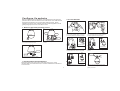
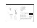
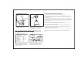
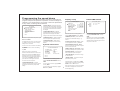
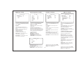
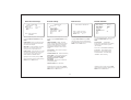
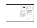
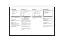
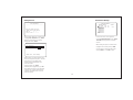
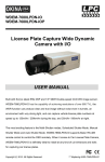
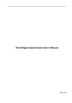
Contents
Before installing
1
Key features
2
New features....................
3
Configure, fix and wire..............
4
Basic speed dome operation
7
Programming the speed dome
8
Parts and dimensions
17
Wiring schematic
18
Specifications
19
Before installing
!
·Installation should be carried out only by qualified personnel and in accordance with
any wiring regulations in force at the time.
·The speed dome is heavy and could cause injury if not correctly mounted in
accordance with these instructions. Use only the fittings supplied with the speed
dome and ensure that all lanyard safety cables are connected correctly during
installation.
·Adequate protection against lightning strikes and power surges must be installed to
prevent damage to the speed dome.
·Any safety warnings on the product and in these instructions must be adhered to.
·If cleaning is necessary, disconnect power to the speed dome first. Do not use
abrasive cleaners, as these will cause damage to the cover and cause poor image
quality. Use a damp cloth to gently clean the dome cover and dry off with a soft
clean cloth.
·Do not use any brackets, mounts or other accessories not specifically designed for
use with this speed dome.
·Do not attempt to service or repair the speed dome as opening or removing covers
may expose dangerous voltages or other hazards. Refer all servicing to qualified
service personnel.
1
Key features
Presets
Up to 127 sets of positional and zoom level information can be stored as
presets. These can be called manually by the operator, automatically by an
alarm input, or grouped to form a sequence of actions to run automatically.
Each preset can also be programmed with the following:
Alarm action - relay outputs can be triggered when particular presets are
called
Title - each preset can be titled with up to 10 characters so that zones can
easily be identified
Privacy zones
By defining a privacy zone, sensitive scenes such as windows can be
masked off so they cannot be viewed by the operator. Up to 8 privacy
zones can be defined. Privacy zone size adjusts automatically depending
on the speed dome zoom level.
Alarm inputs and outputs
This speed dome has 8 alarm inputs and 4 alarm outputs. Any alarm input
can be set to call a predefined preset, scan function, pattern or group. Any
preset can be configured to activate any or all of the alarm outputs. For
example, a PIR detector connected to alarm input 1 could call preset 7 to
view that particular scene whilst activating an external lamp connected to
relay 1 and an external siren connected to relay 3.
Pattern tours
Any dome movement can be recorded - and subsequently played back - as
four separate pattern tours. These can be played back individually or
grouped to form a sequence of tours.
On Screen Display (OSD)
The operator can choose if any or all of the following information is
displayed on screen during normal speed dome operation.
Auto Scan between2presets
Scan is a useful feature when,for example,the operator wishes to ‘patrol’ a
perimeter fence. If one preset is defined at one end of the fence and a
second preset is defined at the other, the scan function will smoothly and
accurately move from one end to the other and then back again in a
repeating sequence. Speed can be adjusted as necessary and up to 8 scan
functions can be defined.
Preset status and title
Speed dome position coordinates and zoom level
Alarm I/O status
·Time and Date
Speed dome ID
Group function
The group function is a powerful feature which allows the operator to define
a sequence of speed dome actions to form an automatic patrol sequence.
Actions can be a mix of preset positions, pattern tours and scan functions.
Up to 8 groups can be defined and each group can have up to 20 actions
which repeat indefinitely until interrupted by the operator or an alarm input.
Specific parameters such as preset speed, dwell time and action loop can
also be specified
The speed dome also has a full on screen menu setup allowing quick and
easy configuration of all the speed dome features.
Powerful park function
The speed dome can be configured to run a specified VST function, pattern
tour, group or preset after a defined period of inactivity.
2
New features
1.
Special Preset setting
The user could set the parameters of focus Mode, Color, WDR,
Stabilizer, Auto slow shutter, White Balance, AE Mode
according to different scene on each preset, in this case, the
camera can always give the best picture quality.
2.
Nest Group
One group could nest another group, one group could only be
nested once.
3.
Schedule function
The user could set a schedule to make the speed dome run
different functions(such as preset, pattern, group, auto scan) at
different time. Up to7 schedules can be defined.
4.
soft camera ID
The user could adjust the camera ID by keyboard, no need to
process on dip switch.
5.
Firmware updating and baut rate adjusting could be processed
in junction box conveniently, no need to open the speed dome
housing.
6.
Pelco D/P and AD protocol are available.
7.
Full duplex RS422 and semideplex RS485 port are available.
The user could select different communication mode by adjusting
dip switch.
8.
Powerful lightningproof design could resist up to 20KV lig htning
or surge.
3
9.
Powerful power supply design
10.
Password protection
The user could set a password for the speed dome to prevent
unpermitted processing.
Configure, fix and wire
3. Fix the bracket
Before proceeding with installation, the speed dome foam packing
pieces must be removed. Remove the outer dome cover with the tool
supplied and carefully remove the foam packing pieces. When
handling the dome cover, always wear the gloves supplied to avoid
getting fingerprints on the outer dome cover.
1. Remove the foam packing pieces
Foam
1. Fix the supplied mounting template, taking
account of any pipework, cables, overhangs
etc. that may obstruct the bracket once fitted.
Foam
2. After making suitable checks for buried
pipes and cables, drill fixing holes suitable for
the bolts supplied with the speed dome.
Foam
1. Wearing the gloves and using the supplied
tool, remove the outer dome cover.
2. Remove the foam pieces from the camera
module.
Pendent option
Pendent option
3. Remove the junction box cover. Using the
supplied bolts and tool, firmly fix the bracket.
Lanyard
4. Feed the speed dome cable through the
bracket.
Lanyard
Cover
3. Carefully unclip the black inner dome
2. Reassemble the speed dome
Pendent option
Refit the black inner dome cover and outer dome cover. If the
lanyard safety wire was removed, it must be refitted before the dome
cover is fixed.
5. Bring the speed dome up to the bracket.
4
6. Tighten the three screws to fix the speed
dome and ensure the lanyard safety chain is
properly connected.
Protocol & Baud rate DIP switch table
4. Complete the install
1
2
3
OFF
OFF
ON
OFF
ON
OFF
ON
OFF
ON
ON
OFF
OFF
ON
ON
OFF
OFF
OFF
ON
ON
ON
ON
Protocol/Rate
PelcoD, 240
00 bps
P elcoP,4800 bps
P elcoP,9600 bps
VC,9600 bps
AD,4800 bps
AD,4800 bps
PelcoD, 48 00 bps
Note: Dip switches 4-6 are reserved
and must not be changed.
Dip4 reserved
Dip5 Rs485/Rs422
Dip6 NTSC/Pal
Speed dome ID DIP switch table
1
1
2
2
3
4
4
8
ON OFF OFF OFF
OFF ON OFF OFF
ON ON OFF OFF
OFF OFF ON OFF
ON OFF ON OFF
OFF ON ON OFF
ON ON ON OFF
OFF OFF OFF ON
5 6 7 8
16 32 64 128
OFF
OFF
OFF
OFF
OFF
OFF
OFF
OFF
OFF
OFF
OFF
OFF
OFF
OFF
OFF
OFF
OFF
OFF
OFF
OFF
OFF
OFF
OFF
OFF
OFF
OFF
OFF
OFF
OFF
OFF
OFF
OFF
–
–
–
–
–
–
–
–
ON
ON
ON
ON
ON
ON
ON
ON
9
–
–
–
–
–
–
–
–
–
–
10 DIP
– VAL/ID
–
1
–
2
–
3
–
4
–
5
–
6
–
7
–
8
– –
255
ON
1
2
3
4
5
7
8
Factory default
switch positions
Speed dome ID is set
using standard
binary notation
Note: ID 0 should not be used. Where multiple speed domes
are connected, a unique ID must be assigned to each one.
Dip switches 9-10 are reserved and must not be changed.
5
6
5. Complete the install
If there’s a problem at this stage...
…work through the logical steps below to determine and rectify the problem
No picture - check the PCB to make sure the red power LED is lit. If not, check that the PSU is
correctly connected and has power. If you have a test meter, verify that the output of the PSU is
approximately 24V AC.
Seal
If the power LED is lit, check the BNC crimp connection is correctly made at both the PCB end and
the DVR / monitor / matrix end. A portable test monitor connected directly to the video output of the
speed dome is also a useful test - if a picture is displayed, double check the BNC connections and
the signal cable used.
Seal
No PTZ control - check that the control equipment you are using is compatible with the speed
dome and is configured to match the speed dome settings correctly.
If dip switches were changed on the speed dome, check the power on self test screen to ensure
that protocol, ID and baud rate are as expected.
1a - wall bracket option. After making all the
connections to the PCB, fit the junction box
cover with the four screws.
1b - pendent option. After making all the
connections to the PCB, raise the dome
assembly to the junction box, connect the
dome cable to the PCB and fix with the four
screws.
If the settings match, you should check the polarity of the connections, both on the control
equipment and the speed dome. If you suspect there is a polarity issue, swap the A & B wires at the
speed dome to see if this resolves the problem.
Check also that there are no other telemetry devices on the system with the same ID as the speed
dome. If in doubt, connect the speed dome directly to the PTZ controller and isolate all other
equipment.
Note: when fixing the cover to the junction box, ensure that the seal is also
fitted properly and that none of the cables are trapped
6. Verify basic operation
HIGH SPEED DOME
-----------------------2.23T27V
FIRMWARE VER
COLOUR SYSTEM : PAL
: PELCO-D
PROTOCOL
: 001
ADDRESS
: 2400
BAUD RATE
: RS485/422
Comm.Mode
: OK
ZOOM MODULE
: OK
ALARM I/O
HOME TEACHING.. WAIT...
1. After carefully checking the installation,
including all cable connections, apply power to
the dome and check that the startup and self
test screen is displayed.
07/JAN/2007
14:46:46
CAM 1
325/37/x1
O:---I:12345678
2. After the self test is complete, the dome
starts normal operation. Verify that there is
basic PTZ control from your control equipment.
6
Basic speed dome operation
Programming, calling and deleting presets
There are many different PTZ keyboards and DVR systems capable
of controlling this speed dome, and it would be impossible to
describe them all here. Therefore, examples given in the following
pages are based on the more popular control equipment available.
Whilst the principles of operation are the same, regardless of the
control equipment used, reference may need to be made to the
manual supplied with your particular control equipment.
11-07-15
12:38:05
Understanding the On Screen Display (OSD)
CAM001 325/37/×001
O:---I:12345678
To program a preset position, move the speed
dome to the desired scene and zoom level
and press:
ACTION TITLE: Shows
current speed dome
action
DATE/CLOCK: Shows
current time and date
Preset001
SET - XXX - ENTER
11-07-15
09:37:15
PRESET3
RECEPTION
Where XXX is a preset number between 1 &
128 (but note that preset 95 is reserved and
cannot be used). Confirmation is displayed on
the OSD.
PRESET LABEL: If defined,
is displayed when a preset
position is called
CAMERA ID: Shows the
current ID as defined by the
dip switch settings
CAM001 307/46/×003
ALARM I/O: Shows which
alarm inputs and outputs are
active
To delete a preset position, press:
CLEAR - XXX - ENTER
Where XXX is a preset number between 1 &
128 (but note that preset 95 is reserved and
cannot be used). The preset position is
cleared from memory.
O:-23I:12345678
PTZ INFORMATION: The current
pan/tilt position in degrees and
the current zoom level
7
11-07-15
12:42:22
CAM001 325/37/×003
P R E S E T 003
PARKING BAY 1
O:---I:12345678
To go to a preset position thats already
been programmed, press:
SHOT - XXX - ENTERXXX - Preset
Where XXX is a preset number between 1 &
128 (but note that preset 95 is reserved and
cannot be used). The speed dome moves to
the preset position. Confirmation and preset
title (if defined) is displayed on the OSD.
To reprogramme a preset position, follow the
steps for programming a preset - it is not
necessary to delete the old preset position first
Programming the speed dome
Display setup
The speed dome setup menu allows the operator to customise and
program all aspects of speed dome operation. All menu settings are
retained in non-volatile memory so if power is lost to the speed dome
for any reason, all settings will be retained.
MAIN MENU
----------------------------<SYSTEM INFORMATION>
<DISPLAY SETUP>
<DOME CAMERA SETUP>
<ALARM SETUP>
<SYSTEM INITIALISE>
<PASSWORD SETUP>
<HELP>
EXIT
To access the speed dome setup menu, key:
SHOT - 95 - ENTER
To navigate the main menu, move the joystick
up / down to choose a menu item or change
settings within a menu item.
To enter a menu item or confirm a new setting,
key: NEAR
To exit a menu item or cancel a new setting,
key: FAR
Where a menu item is surrounded by
brackets, it indicates that there is a sub menu.
Where a menu screen shows EXIT, selecting
this option will exit the menu and the speed
dome will return to normal operation. Where a
menu screen shows BACK, selecting this
option will return to the higher menu level.
The main menu has five options:
<SYSTEM INFORMATION> - Provides
information such as firmware version, protocol
and ID values as defined by the dip switch
settings.
DISPLAY SETUP
----------------------------CAMERA ID
ON/OFF
ACTION TITLE
ON/OFF/AUTO
PTZ INFORMATION
ON/OFF/AUTO
PRESET LABEL
ON/OFF/AUTO
ALARM I/O
ON/OFF
DATE/TIME
ON/OFF/AUTO
<DATE TIME SETUP>
<PRIVACY ZONE>
BACK
EXIT
<DISPLAY SETUP> - Allows the operator to
specify which On Screen Display information
is shown during normal operation. Also allows
privacy zones to be defined and time/date to
be changed
<DOME CAMERA SETUP> - Allows all
operating features of the speed dome to be
programmed and managed. Also allows
settings for the camera module to be changed
From the main menu, use the joystick to
highlight DISPLAY SETUP and key: NEAR
CAMERA ID (ON / OFF) - shows camera ID
according to the DIP switch settings, eg
CAM 1.
<PASSWORD SETUP> - Allows a password
to be set to protect the speed dome setup
<SYSTEM INITIALISE> - Allows various
speed dome settings to be reset to factory
defaults
ACTION TITLE (ON / OFF / AUTO) - shows
current speed dome action, eg PRESET3.
PTZ INFORMATION (ON / OFF / AUTO) shows the current pan / tilt position in degrees
and the current zoom level.
System information
SYSTEM INFORMATION
----------------------------FIRMWARE VER
COLOUR SYSTEM
PROTOCOL
ADDRESS
BAUD RATE
Comm.MODE
PRESET LABEL (ON / OFF / AUTO) - shows
preset title (if defined) when a preset is called.
2.23T27V
:
:
:
:
PAL
PELCO-D
001
2400
RS422/RS485
ALARM I/O (ON/OFF) - shows real time
status of the alarm inputs and outputs.
<DATE TIME SETUP) - sub menu to change
the date and time
BACK
EXIT
<PRIVACY ZONE> - sub menu to setup the
speed dome privacy zones
From the main menu, use the joystick to
highlight SYSTEM INFORMATION and key:
NEAR
Highlight the item to modify and key: NEAR
Use the joystick to change the setting and key:
NEAR to save or: FAR to cancel.
To return to the main menu, highlight BACK
and key: NEAR
To exit the setup menu completely, highlight
EXIT and key: NEAR
8
Note: If the auto option is chosen, the relevant
information is displayed for a few seconds
before disappearing.
DATE TIME SETUP
DATE/TIME SETUP
----------------------------DATE
07-01-07/SUN
TIME
14:37:15
BACK
EXIT
From the display setup menu, use the joystick
to highlight DATE/TIME SETUP and key:
NEAR
Highlight the item to modify and key: NEAR
Move the joystick up and down to change an
individual value and left and right to move to
the previous / next value
PRIVACY ZONE
----------------------------ZONE NO.
1/8
ZONE DISPLAY
CLEAR ZONE
<EDIT ZONE>
BACK
Dome camera setup
Edit zone
Privacy zone
EDIT ZONE 1
-----------------------------
DOME CAMERA SETUP
----------------------------<CAMERA SETUP1>
<CAMERA SETUP2>
<MOTION SETUP>
<PRESET SETUP>
<AUTO SCAN SETUP>
<GROUP SETUP>
<PATTERN SETUP>
<SCHEDULE SETUP>
BACK
EXIT
ON/OFF
CANCEL/YES
EXIT
MOVE TO TARGET POSITION
[NEAR:SELECT/FAR:CANCEL]
From the display setup menu, use the joystick
to highlight PRIVACY ZONE and key: NEAR
From the privacy zone menu, use the joystick
to highlight EDIT ZONE and key: NEAR
ZONE NO. (1-8) - shows the privacy zone
currently being modified.
Use the joystick to move the speed dome to
the approximate position and zoom level for
the privacy zone and key: NEAR to select or
FAR to cancel and return to the privacy zone
menu.
DISPLAY - determines whether the privacy
zone is displayed during normal operation.
Highlight the item to modify and key: NEAR
Use the joystick to change the setting and key:
NEAR to save or: FAR to cancel.
EDIT ZONE 1
-----------------------------
From the dome camera setup menu, use the
joystick to highlight CAMERA SETUP1 and
key: NEAR
<CAMERA SETUP1>,<CAMERA SETUP2>
- setup of specific camera module features.
DIGITAL ZOOM (ON / OFF) - disables or
enables the 10x digital zoom. When disabled,
the maximum zoom level is 36x (optical).
<PRESET SETUP> - full management and
programming of individual presets.
<AUTO SCAN SETUP> - full management
programming of SCAN functions.
<GROUP SETUP> - full management and
programming of group functions.
[L/R:ADJUST ZONE WIDTH]
[U/D:ADJUST ZONE HEIGHT]
[NEAR:SAVE
/FAR:CANCEL]
<PATTERN SETUP> - full management and
programming of pattern tours.
Move the joystick left and right to finely adjust
the width of the privacy zone and up and down
to finely adjust the height.
<SCHEDULE SETUP> - full management and
programming of Schedule.
To save the privacy zone, key: NEAR or key:
FAR to cancel.
Highlight the setup menu required and key:
NEAR
Remember: A menu item surrounded by
brackets shows it has a sub menu.
9
CAMERA SETUP1
----------------------------OFF/ON
DIGITAL ZOOM
AUTO
FOCUS MODE
<WHITE BALANCE>
Î
<AE MODE>
<BACKLIGHT>
<BACKLIGHT>
BACK
EXIT
From the main menu, use the joystick to
highlight DOME CAMERA SETUP and key:
NEAR
<MOTION SETUP> - setup of the pan / tilt /
zoom operation of the speed dome, park
action configuration, and configuration of the
alarm inputs.
<EDIT ZONE> - allows the operator to define
the privacy zone.
Camera setup1
FOCUS MODE
MANUAL - the operator must focus the
camera manually using the NEAR and FAR
keys.
SEMIAUTO - the camera automatically
focuses during normal PTZ movement but
preset focus information is stored when a
preset is programmed and recalled each time
the preset is called
AUTO - the module auto focuses continually
<WHITE BALANCE> - sub menu to change
the white balance settings
<AE MODE> - sub menu to change the auto
exposure settings
<BACKLIGHT>- to change backlight settings.
WB mode setup
WB MODE SETUP
----------------------------WB MODE
AWC
RED ADJUST
--BLUE ADJUST
--BACK
EXIT
Camera setup2
Auto exposure setup
AE SETUP
----------------------------SENS-UP
DAY/NIGHT
SSNR
IRIS LEVEL
AGC LEVEL
SHUTTER SPD
BRIGHTNESS
CAMERA SETUP2
----------------------------PIC FREEZE
OFF
PIC FLIP
OFF
ZOOM SPEED
7
FLICKERNESS
OFF
OFF
STABALIZER
BACK
EXIT
OFF
AUTO
OFF
AUTO
OFF
ESC
054
BACK
EXIT
Motion setup
MOTION SETUP
----------------------------ON
AUTO FLIP
SLOW
JOG SPEED
NOR
JOG DIRECTION
ON
PWR UP ACTION
ZOOM PROPORTIONAL ON
OFF
PRESET LOCK
<PARK ACTION>
BACK
EXIT
From the zoom camera setup menu, use the
joystick to highlight WHITE BALANCE SETUP
and key: NEAR
From the zoom camera setup menu, use the
joystick to highlight AUTO EXPOSURE
SETUP and key: NEAR
From the dome camera setup menu, use the
joystick to highlight MOTION SETUP and key:
NEAR
From the dome camera setup menu, use the
joystick to highlight MOTION SETUP and key:
NEAR
WB MODE
SENSUP (OFF/ ON) -operator can select
sensup mode,
PIC FREEZE - when set to ON, there’s no
image flash.
DAY/NIGHT (AUTO/DAY/NIGHT) - the
operator can choose to fix the camera in to
DAY (colour) or NIGHT (B&W with IR cut filter
mode). In AUTO mode, the camera switches
between DAY and NIGHT depending on the
surrounding light level
SSNR- select ON/OFF
IRIS LEVEL- select IRIS level
AGC LEVEL- select AGC level
SHUTTER SPD- select shutter speed
BRIGHTNESS- adjust brightness level
PIC FLIP - when set to ON, the image will be
turned 180 degrees.
AUTO FLIP (ON / OFF) - when set to ON, the
dome will flip 180 degrees when the tilt
position reaches 90 degrees.
AWC- the speed dome determines the
optimum white balance settings for a given
scene
MANUAL - the operator can adjust white
balance settings manually
iNDOOR- indoor mode
OUTDOOR-outdoor mode
ATW-auto trace white balance mode
RED ADJUST - in manual mode, the red
colour content can be adjusted
BLUE ADJUST - in manual mode, the blue
colour content can be adjusted
ZOOM SPEED - Operator can select zoom
speed.
FLICKERNESS - Should be set to ON when
used in certain lighting conditions (EG
Fluorescent lighting) to prevent picture flicker.
STABILIZER - Used to select stabilizer mode
PWR UP ACTION - when set to ON, the
speed dome will resume its last operation
when power is restored after a power failure
<PARK ACTION> - Configure actions that run
automatically after a defined period of
inactivity
BLC
HLC MODE ----USER BLC SET
BACK
EXIT
BACKLIGHT (BLC/HLC/OFF) -operator can
select back light mode
HLC MODE (LOW/OFF/HIGH) -operator can
select HLC mode
USER BLC SET - set BLC position and size
JOG DIRECTION (INVERSE / NORMAL) when set to normal, the pan direction is
opposite to the joystick movement.
<ZOOM PROPORTIONAL> - used to select
zoom proportion.
BACKLIGHT SETUP
----------------------------BACKLIGHT
JOG SPEED - determines the maximum
speed in degrees / second the dome will move
during manual operation
Highlight the item to modify and key: NEAR
Use the joystick to change the setting and key:
NEAR to save or: FAR to cancel.
10
PRESET LOCK - when set to ON, preset
programming directly from the keyboard is
disabled to prevent tampering
Highlight the item to modify and key: NEAR
Use the joystick to change the setting and key:
NEAR to save or: FAR to cancel.
Park action setup
PARK ACTION SETUP
----------------------------PARK ENABLE
OFF
PARK T I M E
00:10:00
PARK ACTION
HOME
BACK
EXIT
NOTE: PARK TIME UNITS
IS SECONDS
Preset setup
PRESET SETUP
----------------------------PRESET NO.
001
From the dome camera setup menu, use the
joystick to highlight PRESET SETUP and key:
NEAR
PARK ENABLE - when set to ON, the speed
dome will run the specified park action after
the wait time has elapsed
PRESET NUMBER (1 - 128) - The preset
number currently being modified. If the preset
number is already defined, the speed dome
will move to that preset position, otherwise
UNDEFINED is displayed under the preset
number
PARK ACTION - choose the action to run after
the wait time has elapsed. This can be return
to home position, go to a preset or run a
SCAN, GROUP or PATTERN TOUR
Highlight the item to modify and key: NEAR
Use the joystick to change the setting and key:
NEAR to save or: FAR to cancel.
EDIT SCENE - PRESET 001
-----------------------------
<EDIT SCENE>
<PRESET DEFAULTS>
<EDIT LABEL>
C L EAR P R E S E T
CANCEL
RELATE ALARM
NONE
BACK
EXIT
From the motion setup menu, use the joystick
to highlight PARK ACTION SETUP and key:
NEAR
WAIT TIME - can be set between one minute
and 4 hours. If no manual control occurs
during this time, the park action will run
Edit scene
Preset defaults
PRESET DEFAULTS
PRE-001
----------------------------CLEAR DEFAULTS
CANCEL
FOCUS MODE
AUTO
STABALIZER
OFF
<BLACKLIGHT>
MOVE TO START POSITION
[ N E A R : SELECT F A R : C A N C E L ]
CAM 001
O:---006/02 X001
I:----
From the preset setup menu, use the joystick
to highlight EDIT SCENE and key: NEAR
Using the joystick, move the speed dome to
the desired position and zoom level and key:
NEAR to save or: FAR to cancel.
<WHITE BALANCE>
<AE MODE>
SAVE
BACK
EXIT
YES
From the motion setup menu, use the joystick
to highlight PRESET DEFAULTS and key:
NEAR
- YES/CANCEL
Preset defaults
for each preset, specifies the camera setting.
following items are available only when
Y Y Y YUyes is selected.
Focus mode - AUTO/SEMIAUTO/MANUAL
STABILIZER - select stabilizer setting
BACKLIGHT - select backlight setting
WHITE BALANCE - select WB setting
AE MODE - select AE setting
<EDIT SCENE> - use this option to program
the preset position
<PRESET DEFAULTS> - define default setting
<EDIT LABEL> - use to edit the preset label.
This option is only available when the
selected preset position is already
programmed
CLR PRESET - use this option to delete the
current preset position
RELATE ALARM- set to relate alarm
Highlight the item to modify and key: NEAR
Use the joystick to change the setting and key:
NEAR to save or: FAR to cancel.
Highlight the item to modify and key: NEAR
Use the joystick to change the setting and key:
NEAR to save or: FAR to cancel.
11
Edit label
PRESET LABEL SETUP
----------------------------LAB FOR PRE
---------1234567890
ABCDEFGHIJ
KLMNOPQRST
UVWXYZ - .
SAVE
CANCEL
CLEAR
CANCEL
BACK
EXIT
From the preset setup menu, use the joystick
to highlight EDIT LABEL and key: NEAR
The solid white square shows the current
cursor position.
The flashing white square shows the currently
selected character.
Move the joystick up / down / left / right to
choose the required character and key: NEAR
to insert it in the preset label. The solid white
square moves to the next cursor position.
Repeat until the preset label is complete.
If a mistake is made, use the joystick to select
the backspace ( ) and key: NEAR. The cursor
moves back one square.
Select OK to save the preset label or
CANCEL to lose changes, and key: NEAR to
exit
Auto Scan Setup
vSCAN SETUP
----------------------------SCAN NO.
1/8
1ST POS.
NONE
2ND POS.
NONE
SCAN SPEED
030
DIRECTION
NORMAL
CLEAR SCAN
CANCEL
RUN SCAN
BACK
EXIT
From the dome camera setup menu, use the
joystick to highlight SCAN SETUP and key:
NEAR
SCAN NO. (1-8) - shows the SCAN number
currently being modified.
1ST POS. - any defined preset between 1 &
127.
2ND POS. - any defined preset between 1
&127.
SCAN SPEED - determines the speed of
movement in degrees per second between
each preset position.
CLEAR SCAN - deletes the currently selected
VST function.
RUN SCAN - runs the currently selected
SCAN function for testing purposes
Highlight the item to modify and key: NEAR
Use the joystick to change the setting and key:
NEAR to save or: FAR to cancel.
Note:AV Vscan always moves anti-clockwise to
the 1st position and then clockwise to the 2nd
position.
12
GROUP SETUP
----------------------------1/8
GROUP NO.
SAVE GROUP
CLEAR GROUP
RUN GROUP
<EDIT GROUP>
BACK
EXIT
Edit group
Edit group
Group setup
CANCEL
CANCEL
From the dome camera setup menu, use the
joystick to highlight GROUP SETUP and key:
NEAR
GROUP NO. (1-8) - shows the group number
currently being modified.
CLEAR GROUP - the currently selected group
can be deleted
RUN GROUP - runs the currently selected
group for testing purposes
<EDIT GROUP> - allows the operator to
program the group functions. operator can edit
new nesting group action in each group
Highlight the item to modify and key: NEAR
Use the joystick to change the setting and key:
NEAR to save or: FAR to cancel.
EDIT GROUP 1
----------------------------NO ACTION AAA DWELL OPT
----------------------------1 PATTERN 1 00:03
1
2 PRESET
5 00:08 360
3 SCAN
3 00:03
8
4 PRESET 10 00:15 110
5 PRESET
4 01:30
55
----------------------------BACK
CANCEL
[NEAR:EDIT]
EDIT GROUP 1
----------------------------NO ACTION AAA DWELL OPT
----------------------------1 PRESET 001 00:03 360
2 NONE
3 NONE
4 NONE
5 NONE
----------------------------BACK
CANCEL
From the group setup menu, use the joystick
to highlight EDIT GROUP and key: NEAR
Key NEAR to save this item and continue
adding more items as necessary, or key FAR
to exit.
To edit the group, key: NEAR again
Pattern setup
PATTERN SETUP
----------------------------PATTERN NO.
1/4
CLEAR PATTERN CANCEL
RUN PATTERN
<EDIT PATTERN>
BACK
EXIT
From the dome camera setup menu, use the
joystick to highlight PATTERN SETUP and
key: NEAR
PATTERN NO. (1 - 4) - The pattern number
currently being modified.
Header explanation:
NO - the item number (between 1 & 20)
ACTION - the specific action for this item
AAA - the action number (eg if ACTION is set
to PRESET, this value can be between 1 &128
DWELL - the amount of time before the next
action in the list is called
OPT - for PRESET actions, this value is the
speed at which the dome moves to the preset.
For SCAN and PATTERN, this value is the
number of times the action is repeated before
the next action is called
CLEAR PATTERN - the currently selected
pattern can be deleted
RUN PATTERN - runs the currently selected
pattern for testing purposes
<EDIT PATTERN> - allows the operator to
program a patten tour
Highlight the item to modify and key: NEAR
Use the joystick to change the setting and key:
NEAR to save or: FAR to cancel.
Move the joystick up and down to choose the
group item to modify and key: NEAR. The
ACTION is highlighted in white
Move the joystick up and down to change the
action type between NONE, PRESET, SCAN
and PATTERN.
Move the joystick left and right to select and
edit values for AAA, DWELL & OPT.
13
Schedule Setup
Edit pattern
SCHEDULE SETUP
----------------------------MASTER ENABLE
ON/OFF
DAY TIME
ACT
NO.
1 MON 00:00 PAT 001
OFF
2 UNDEFINED
3 UNDEFINED
4 UNDEFINED
5 UNDEFINED
6 UNDEFINED
7 UNDEFINED
BACK
EDIT PATTERN 4
-----------------------------
MOVE TO START POSITION
[NEAR:START /FAR:CANCEL
CAM 001
O ---0 0 9 / 0 6 X 0 0 1 I --------
From the pattern setup menu, use the joystick
to highlight EDIT PATTERN and key: NEAR
From the main menu, use the joystick to
highlight SYSTEM INITIALISE and key: NEAR
Position the speed dome to the desired
starting point and key: NEAR
DAY TIME- selecting this option to set date
and time
ACT- selecting this option to set dome motion
EDIT PATTERN 4
Highlight the item to modify and key: NEAR
Use the joystick to change the setting to ON
and key: NEAR to run or: FAR to cancel.
[NEAR:SAVE
/FAR:DELETE]
Move the dome to the various positions and
zoom levels required for the pattern. The white
squares at the top of the display show
remaining storage and disappear as the
pattern is recorded.
To save the pattern, key: NEAR
To abandon pattern programming, key: FAR
Note: Pattern tour memory is only used when
movements are recorded. Pauses between
movements, regardless of time, do not use
pattern tour memory
14
Alarm Setup
ALARM SETUP
----------------------------ALARM IN CHANEL
LS
101
/ 8/ 16
ALARM ENABLE
OFF
RELATE PRESET
RELATE RELAY OUT
---INPUT SETUP
RELAY ACTIVE TIME
SAVE
YES
<ALARM POSITION>
BACK
EXIT
From the main menu, use the joystick to
highlight ALARM SETUP and key: NEAR
System Initialise
Password setup
PASSWORD SETUP
----------------------------CHECK PASSWORD
OFF
<EDIT PASSWORD>
SAVE
CANCEL
BACK
EXIT
SYSTEM INITIALISE
----------------------------CLEAR ALL DATA
NO.
CLR DISPLAY SET
NO.
CLR CAMERA SET
NO.
NO.
CLR MOTION SET
NO.
CLR EDIT DATA
NO.
REBOOT CAMERA
NO.
REBOOT SYSTEM
BACK
EXIT
From the main menu, use the joystick to
highlight SYSTEM INITIALISE and key: NEAR
ALARM IN CHANEL - selecting alarm chanel
ALARM ENABLE - this option will enable
alarm function
RELATE PRESET - selecting related preset
RELATE RELAY OUT - selecting related relay
out
INPUT SETUP - set up alarm input
RELAY ACTIVE TIME - set relay active time.
<ALARM POSITION> -
select alarm position
Highlight the item to modify and key: NEAR
Use the joystick to change the setting to ON
and key: NEAR to run or: FAR to cancel.
CLEAR ALL DATA - selecting this option will
perform a full factory reset on the speed
dome. All presets, scan functions, patterns,
groups and privacy zones will be erased
From the main menu, use the joystick to
highlight PASSWORD SETUP and key: NEAR
CHECK PASSWORD (ON/OFF) - when set to
ON, the correct password must be entered to
access the speed dome setup menus
<EDIT PASSWORD> - allows the current
password to be changed
SAVE - to save current password.
CLR DISPLAY SET - this option will reset the
on screen display settings to factory default
and erase all privacy zones
Edit Password
Password setup
-----------------------------
INPUT CURRENT PASSWORD:
11111111
From the password setup menu, use the
joystick to highlight EDIT PASSWORD and
key: NEAR
Default password is 11111111
The solid white square shows the current
cursor position.
This flashing white square shows the currently
selected character.
Move the joystick up / down / left / right to
choose the required character and key: NEAR
to insert it in the password. The solid white
square moves to the next cursor position.
Repeat until password entry is complete.
CLR CAMERA SET - this option will reset the
camera module settings to factory default
CLR MOTION SET - this option will reset the
motion menu settings to factory default
If a mistake is made, use the joystick to select
the backspace ( ) and key: NEAR. The cursor
moves back one square.
CLR EDIT DATA - this option will erase all
presets, VST functions, patterns and groups
Select OK to save the password or CANCEL
to lose changes and key: NEAR to exit
Highlight the item to modify and key: NEAR
Use the joystick to change the setting to ON
and key: NEAR to run or: FAR to cancel.
Remember: When CHECK PASSWORD is set
to ON, each time the operator attempts to
enter the speed dome setup menu, the above
screen will be displayed. The correct
password must be entered to continue with
menu setup
15
System Help
SYSTEM HELP
----------------------------IN COMMON USE,
FOLLOW KEY TO CONTROL MENU:
JOG U/D/L/R TO SELECT
FOCUS NEAR TO CONFIRM
FOCUS FAR TO CANCEL
BACK
EXIT
Calling the actions
Shortcut Menu
Once the pattern tours, scan
functions and groups have been
programmed in the speed dome
setup menu, they can all be
accessed directly from the PTZ
control equipment by using the
following sequences.
1. To start a pattern tour press:
SHOT - 13X - ENTER
From the main menu, use the joystick to
highlight SYSTEM HELP and key: NEAR
Highlight the item to modify and key: NEAR
Use the joystick to change the setting to ON
and key: NEAR to run or: FAR to cancel.
Where X is a pattern tour number between
1&4
The selected pattern tour will run
indefinitely until a manual movement is
made by the operator or an alarm input is
received.
SHOT - NO.-ENTER
FUNCTION
0 (TWICE)
ENTER MAIN MENU
33
RESERVED
34
RESERVED
62
RESERVED
63
RESERVED
92
RESERVED
93
RESERVED
94
REMOTE RESET
95
ENTER MAIN MENU
131-134
CALL PATTERN
141-148
CALL SCAN
2. To start a scan function, press:
151-158
CALL GROUP
SHOT - 14X - ENTER
161-165
RESERVED WORD
Where X is a scan function number
between 1 & 8
170
WDR OFF
The selected scan function will run
indefinitely until a manual movement is
made by the operator or an alarm input is
received.
3. To start a group, press:
SHOT - 15X - ENTER
Where X is a group number between 1 & 8
The selected group will run indefinitely
until a manual movement is made by the
operator or an alarm input is received.
16
171
WDR ON
172
AE AUTO
173
SET SHUTTER SPEED TO 1/120 SEC
Parts and dimensions
Bracket Joint
Housing Upper Cover
PCB
138
59
300
248
42
Thermostat
Heater
Bracket Mount
Base
91
Thermostat
Bracket Upper
Cover
33
33
140
Shield Mount
Tilt Motor
Dome Housing
Inner dome cover
19
Dome Cover
Pan Motor
156
Zoom Module
17
201
230
325
Sunshield
53
Fan
Seal
Wiring schematic
Power Cable
24V AC PSU
Video Cable
RS- 485
Cable
Alarm Input
Cable
Alarm Output
Cable
Alarm Sensor
Siren / Light etc.
power source
Siren / Light etc.
18
Specifications
Camera
Pan / Tilt
CCD
¼”
Resolution
680TVL B/W, 560TVL COLOR
Minimum Illumination
0.2 Lux COLOR, 0.02 B/W
Optical Zoom
27x f=3.5 ~ 94.5mm, F=1.6~3.9
Digital Zoom
16X
S/N Ratio
52db
Focus
Auto / Manual
White Balance
AWC/ Manual/Outdoor/Indoor/Auto
Back Light compensation
Low/ HLC / Off
General
Pan: 360 degrees continuous rotation
Tilt: 90 degrees with auto flip function
Speeds
Manual / pattern tour: 1 - 255 degrees / second
Preset to preset: 360 degrees / second
VST: 1 - 255 degrees / second adjustable in 1 degree steps
Communication
Mechanical
Preset positions
Up to 128, 10 character title per preset
Pattern tours
Up to 4
VSTfunction
Up to 8, speed adjustable
Groups
Up to 8, each with up to 20 actions (preset, pattern tour or VST)
Privacy zones
Up to 4, user definable
Park function
Park to specified preset, pattern or VST after a defined period of inactivity (1 min ~ 4 hours)
Data type
RS-485/RS422
Protocols
Pelco-D or Pelco-P
Baud rates
2400, 4800, 9600
Camera ID
1-255
Alarm I/O
8 inputs, 4 outputs
On Screen Display
OSD menu, camera position, dome ID, alarm status, preset / VST/ pattern tour status
Fan / Heater
Built in
Sunshield
Fitted
Operating temperature range
-35 deg C to +50 deg C
Humidity
<95%
Power supply
24VAC, 20 watts / 24V AC,60 watts (heater on)
Dimensions (with standard wall
Overall height: 530mm
Bracket and sun shield fitted)
Overall width: 230mm
Overall depth: 342mm
19