1
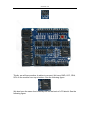
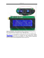
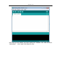
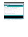
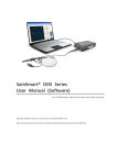
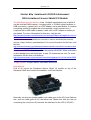
SainSmart.com
Starter Kit:SainSmart LCD2004+Sainsmart
UNO+SainSmart Sensor Shield V4 Module
The SainSmart Uno for Arduino: It has 14 digital input/output pins (of which 6
can be used as PWM outputs), 6 analog inputs, a 16 MHz crystal oscillator, a
USB connection, a power jack, an ICSP header, and a reset button. It contains
everything needed to support the microcontroller; simply connect it to a
computer with a USB cable or power it with a AC-to-DC adapter or battery to
get started. For more information for this item, visit this site:
http://www.sainsmart.com/sainsmart-uno-atmega328p-pu-atmega8u2-microco
ntroller-for-arduino.html
The SainSmart sensor shield can connect to various modules like sensors,
servos, relays, buttons, potentiometers. For more information for this item, visit
this site:
http://www.sainsmart.com/sainsmart-sensor-shield-v4-module-for-arduino-due
milanove-uno-mega2560-atmel.html
SainSmart LCD2004: 5 volt, based on the popular HD44780. White characters
on blue background, with back light. 4 rows, 20 characters per row. For more
information for this item, visit this site:
http://www.sainsmart.com/module/lcd-module/sainsmart-iic-i2c-twi-serial-2004
-20x4-lcd-module-shield-for-arduino-uno-mega-r3.html
Things Needed: Jumper cables, USB cable and the kit
User Manual:
First of all, mount the Sainsmart Sensor Shied V4 module on top of the
Sainsmart UNO and connect the headers. It will look like this:
Secondly, connect two jumper cables, one cable goes to the IIC(1 and 2)above
line, and one cable goes to IIC the below line. Make sure that you are not
connecting the com(2 and 3), because the interface for the LCD is IIC(I2C).
SainSmart.com
Thirdly, we will have another 4 cables to connect. We have GND, VCC, SDA,
SCL on the module from top to bottom. See the following figure:
We also have the same four buckled ports on the back of LCD shield. See the
following figure:
SainSmart.com
plug in accordingly. Then it should be GND on module connecting GND on
LCD shield and the rest should be done in the same way.
Then connect it to your computer using a USB cable as you normally would.
Next, set up your development environment is to go to the arduino website:
www.arduino.cc and click up a software link and download the arduino
software depending on what your platform it is. When finish the download,
open the software and this application will pop up like this:
SainSmart.com
then click up the sketch you have under the “libraries” file. Here we have
“sainlcdtest”, click it and it will show like this:
SainSmart.com
next click up the “upload”, then you will have the software in the sainsamrt
UNO and the LCD will be on with the words showing.