1
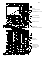
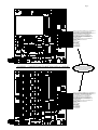
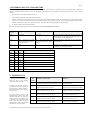
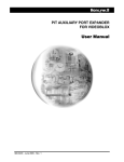
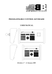
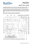
PAN TILT ZOOM TELEMETRY RECEIVER
USER MANUAL
Revision 4.05 –26 October 1999
Page 2
1. INTRODUCTION ....................................................................................................................................................... 3
2. CONNECTIONS.......................................................................................................................................................... 3
2.1. CONFIGURATION FOR AUTO-PAN ............................................................................................................................ 3
2.1. ALARM PRESET RECALL ......................................................................................................................................... 3
3.
EXCLUSION ZONES............................................................................................................................................. 8
4. SWITCH SETTINGS ................................................................................................................................................... 8
4.1. ADDRESS SELECTION ............................................................................................................................................ 8
4.2. BAUD RATE SELECTION ........................................................................................................................................ 8
5. RESTORING DEFAULT PARAMETERS................................................................................................................ 9
6. SYSTEM TESTS ......................................................................................................................................................... 9
IMPORTANT SAFETY INFORMATION
This equipment uses a mains supply voltage which can be lethal if correct
safety procedures are not adhered to.
This equipment must be earthed.
Depressing the test switch can cause the Pan / Tilt unit connected to this
equipment to move. Ensure that such movement will not endanger people or
equipment.
Page 3
1. INTRODUCTION
The Betatech pan tilt zoom (PTZ) telemetry receiver allows for the control of pan tilt (PT) heads and zoom lenses via a serial RS 485 data link.
The PTZ receiver consists of two printed circuit boards, a main control board (bottom) and a PT head interface board (top). The PT interface board
is available in AC and DC versions, allowing for the control of virtually all PT head types.
2. CONNECTIONS
Great care must be taken in the connection of the PTZ telemetry receiver. There are many connections, which, if erroneously connected, could
cause severe damage to the PTZ telemetry receiver, the PT head and the lens. Double check all connections before switching on the mains
power.
Fig 1 shows the general layout of the PTZ receiver circuit board.
Connection of the PTZ telemetry unit is as follows:
•
The PTZ receiver is mains powered. With reference to Fig 3, connect the 220 VAC to the screw terminals marked “220 VAC LIVE IN”, “220
VAC NEUTRAL IN” and “EARTH IN” on the PTZ driver board. Note that these connections are not marked on the DC driver board. Should
it be necessary to operate the PTZ telemetry receiver from a different supply voltage, please contact your nearest Betatech dealer for further
information.
•
For use with an AC PTZ head ensure that the AC driver board is installed. This board is labeled “PTZ AC DRIVER”.
1.
If the PT head is 220 VAC powered, connect JP1 “220 VAC FUSED LIVE OUT” and “220 VAC FUSED NEUTRAL OUT” to
JP2 “AC1 PAN, TILT AND AUX 1&2 LIVE FEED” and “AC1 PAN, TILT AND AUX 1&2 NEUTRAL FEED”.
2.
If the PT head is 24 VAC powered, connect JP1 “24 VAC LIVE OUT” and “24 VAC NEUTRAL OUT” to JP2 “AC1 PAN, TILT
AND AUX 1&2 LIVE FEED” and “AC1 PAN, TILT AND AUX 1&2 NEUTRAL FEED”.
3.
Should auxiliary outputs 2 and 3 be required, connect the required voltage feed (either 220 VAC or 24 VAC) from JP1 to the AC2
feed. Note that this circuit is independent of AC1. It is therefore possible to power the AC1 circuit with a different AC voltage to
AC2.
4.
Connect the pan and tilt motors to the connections shown in Fig 3.
•
For use with a DC PTZ head ensure that a DC driver board is installed. This board is labeled “PTZ DC DRIVER” as shown in Fig 3.
Connect the pan and tilt motors to the connections shown in Fig 3.
•
Connect the lens to the connections shown in Fig 2. Ensure that the lens polarity is correct so that the lens function directions are not reversed.
If an auto-iris lens is used, no iris connection to the PTZ telemetry is required, the auto iris control signals are generated by the camera and
must be connected as described in the camera / zoom lens technical literature.
•
Connect the RS485 communications to the “RS485+”, “RS485-“ and “GROUND” connections shown in Fig 2. Ensure that the polarity is
correct. The RS485 connections are internally protected against limited overvoltages. In areas where there is a high risk of lightning, such as
when the unit is used outdoors with long cable runs, it is recommended that additional external RS485 lightning protection devices are
installed.
•
Should preset positioning be required, connect the lens and pan tilt head feedback potentiometers to the relevant connections on the PTZ
telemetry RX. It is essential that the feedback pots are connected to provide position reference voltages which increase when the PT telemetry
provides an increasing control signal. Feedback voltages must be as follows:
∗
∗
∗
∗
∗
•
Increasing for pan right, decreasing for pan left
Increasing for tilt up, decreasing for tilt down
Increasing for zoom in, decreasing for zoom out
Increasing for focus near, decreasing for focus far
Increasing for iris open, decreasing for iris close
The “FB VREF+” and “GND” (GROUND REFERENCE x FOR PRESETS) connections provide the excitation voltage which must be
connected across the feedback potentiometer. The potentiometer wiper then provides a voltage which is proportional to the position of the lens
/ pan / tilt. The wiper for each function must be connected to the FEEDBACK input on the bottom board connections as shown in figure 2.
Note that two separate excitation signals are provided. These are internally connected and the dual connections allow for one reference
connection to the pan / tilt head and one to the lens.
External Betatech devices, which utilise the Philips I2C protocol, may be connected to the I2C interface connector. This allows for the
connection of additional alarm inputs, auxiliary outputs and local keyboard control.
2.1. Configuration for Auto-Pan
Should the system be required to operate in auto-pan mode, it is necessary to tie the input marked as “TAMPERSW” to “GROUND”. In this mode
Auxiliary output 1 cannot be operated by means of the Aux 1 control on the PCK. When operating Aux 5 (AutoPan), the Aux 1 output will be
activated. When Aux 5 is toggled off, or any pan operation is initiated, the system will exit auto-pan mode. Aux 1 must be connected to the autopan input of the Pan Tilt head.
Note that when configured for auto-pan, the operation of the aux 1 output is limited in test mode to prevent driving the pan motor and aux 1 output
simultaneously.
CHECK ALL CONNECTIONS AGAIN BEFORE SWITCHING ON!!
2.1. Alarm Preset Recall
Alarms may be handled by attaching an I2C input unit (set to address zero) to the PTZ. A contact closure on inputs 1 to 16 will cause preset position
1 to 15 to be recalled.
Page 4
If input 16 is tied active, then contact opening on inputs 1 to 15 will cause preset positions 1 to 15 to be recalled.
Page 5
PAN AND TILT LEDS
DIP SWITCH 1
DIP SWITCH 2
DC PAN TILT AND AUX CONNECTIONS
MAIN STATUS LED
TEST SWITCHES 1 AND 2
PAN AND TILT BRAKE / AUX 1 AND AUX 2 LEDS
AUX 3 AND AUX 4 LEDS
AUX 3 AND AUX CONNECTIONS
BOTTOM PCB CONNECTIONS
MAINS IN AND OUT CONNECTIONS
F1 FUSE 5X20MM 4A SLO BLOW
F1 FUSE 5X20MM 1A SLO BLOW
TRANSFORMER CONNECTIONS
BOTTOM BOARD - CPU LED
PAN TILT ZOOM LEDS
EARTHING WIRE AND LUG - DO NOT REMOVE
FIGURE 1 - GENERAL LAYOUT
PAN AND TILT LEDS
DIP SWITCH 1
DIP SWITCH 2
PAN TILT AND AUX 1 CONNECTIONS
2
I C CONNECTIONS
MAIN STATUS LED
TEST SWITCHES 1 AND 2
MAINS IN AND OUT CONNECTIONS
BOTTOM PCB CONNECTIONS
F1 FUSE 5X20MM 1A SLO BLOW
F2 FUSE 5X20MM 5A SLO BLOW
ZOOM FOCUS IRIS LEDS
EARTHING WIRE AND LUG - DO NOT REMOVE
TRANSFORMER CONNECTIONS
BOTTOM BOARD - CPU LED
back
Page 6
POSITIVE VOLTAGE REFERENCE 1 FOR PRESETS
TILT FEEDBACK VOLTAGE FOR PRESETS
POSITIVE VOLTAGE REFERENCE 2 FOR PRESETS
PAN FEEDBACK VOLTAGE FOR PRESETS
GROUND REFERENCE 1 FOR PRESETS
IRIS FEEDBACK VOLTAGE FOR PRESETS
GROUND REFERENCE 2 FOR PRESETS
FOCUS FEEDBACK VOLTAGE FOR PRESETS
TAMPER SWITCH
ZOOM FEEDBACK VOLTAGE FOR PRESETS
TAMPER SW GROUND RETURN
RS485+ COMMS
GROUND
RS485- COMMS
IRIS MOTOR +
IRIS MOTOR FOCUS MOTOR +
FOCUS MOTOR ZOOM MOTOR +
ZOOM MOTOR -
FIGURE 2 - CONNECTIONS TO BOTTOM PCB AC AND DC
NOTE CONNECTIONS ON BOTTOM
BOARD ARE THE SAME FOR BOTH
AC AND DC DRIVER BOARD
CONFIGURATIONS
POSITIVE VOLTAGE REFERENCE 1 FOR PRESETS
TILT FEEDBACK VOLTAGE FOR PRESETS
POSITIVE VOLTAGE REFERENCE 2 FOR PRESETS
PAN FEEDBACK VOLTAGE FOR PRESETS
GROUND REFERENCE 1 FOR PRESETS
IRIS FEEDBACK VOLTAGE FOR PRESETS
GROUND REFERENCE 2 FOR PRESETS
FOCUS FEEDBACK VOLTAGE FOR PRESETS
TAMPER SWITCH
ZOOM FEEDBACK VOLTAGE FOR PRESETS
TAMPER SW GROUND RETURN
RS485+ COMMS
GROUND
RS485- COMMS
IRIS MOTOR +
IRIS MOTOR FOCUS MOTOR +
FOCUS MOTOR ZOOM MOTOR +
ZOOM MOTOR -
Page 7
PAN MOTOR PAN MOTOR +
TILT MOTOR TILT MOTOR+PAN BRAKE PAN BRAKE +
TILT BRAKE TILT BRAKE +
POSITIVE 12/24 VDC
AUX OUTPUT 1
POSITIVE 12/24 VDC
AUX OUTPUT 2
AC AUX 3 AND 4 NEUTRAL FEED
AC AUX 3 AND 4 LIVE FEED
AUX 4 LIVE
AUX 4 NEUTRAL
AUX 3 LIVE
AUX 3 NEUTRAL
220 VAC LIVE IN
220 VAC NEUTRAL IN
220 VAC FUSED LIVE OUT
220 VAC NEUTRAL OUT
EARTH TO CHASSIS
EARTH IN
18 VAC LIVE OUT
18 VAC NEUTRAL OUT
FIGURE 3 - CONNECTIONS TO TOP PCB AC AND DC
AC1 TILT UP MOTOR NEUTRAL
AC1 TILT UP MOTOR LIVE
AC1 TILT DOWN MOTOR NEUTRAL
AC1 TILT DOWN MOTOR LIVE
AC1 PAN LEFT MOTOR NEUTRAL
AC1 PAN LEFT MOTOR LIVE
AC1 PAN RIGHT MOTOR NEUTRAL
AC1 PAN RIGHT MOTOR LIVE
AC1 AUX 1 NEUTRAL
AC1 AUX 1 LIVE
AC1 PAN, TILT AND AUX 1 & 2 NEUTRAL FEED
AC1 PAN, TILT AND AUX 1 & 2 LIVE FEED
EARTH
EARTH
EARTH
EARTH
AC2 AUX 2 NEUTRAL
AC2 AUX 2 LIVE
AC2 AUX3 NEUTRAL
AC2 AUX3 LIVE
AC2 AUX 2 & 3 NEUTRAL FEED
AC2 AUX 2 & 3 LIVE FEED
220 VAC LIVE IN
220 VAC NEUTRAL IN
220 VAC FUSED LIVE OUT
220 VAC NEUTRAL OUT
EARTH TO CHASSIS
EARTH IN
24 VAC LIVE OUT
24 VAC NEUTRAL OUT
Page 8
3.
EXCLUSION ZONES
It is possible to set up exclusion zones, into which the PTZ may not be directed. In order for this feature to be available, the PTZ MUST be equipped
with feedback potentiometers on pan and tilt. Eight exclusion zones are available.
When auxiliary output 63 is switched on, the
exclusion zones are overridden and the PTZ may
be freely pointed to any direction. Turning the
auxiliary output off, once again limits PTZ
movement. Note that when the PTZ is first
switched on, the PTZ is excluded from pointing
into the specified areas.
Zone
Number
Clear
Zone
Set / Recall
Top Left
Set / Recall
Bottom Left
Set / Recall
Top Right
Set / Recall
Bottom Right
1
Store 11
Pos 21
Pos 31
Pos 41
Pos 51
2
Store 12
Pos 22
Pos 32
Pos 42
Pos 52
3
Store 13
Pos 23
Pos 33
Pos 43
Pos 53
4
Store 14
Pos 24
Pos 34
Pos 44
Pos 54
5
Store 15
Pos 25
Pos 35
Pos 45
Pos 55
6
Store 16
Pos 26
Pos 36
Pos 46
Pos 56
7
Store 17
Pos 27
Pos 37
Pos 47
Pos 57
8
Store 18
Pos 28
Pos 38
Pos 48
Pos 58
Setting up of the exclusion zones is carried out
as follows:
•
•
•
Turn on auxiliary output 64.
Set two opposite corners for the zone(/s).
Turn off auxiliary output 64.
While in setup mode the exclusion zones are set
up by storing and recalling preset positions. The
following table describes the operation for
storing / recalling certain positions:
4. SWITCH SETTINGS
4.1.
Address Selection
Set DIP switch 1, switches 1
to 7 to the required address
of the PTZ. This would
usually match the camera
number in the system. The
actual switch setting is the
binary representation of the
address. The following table
shows
the
first
few
addresses:
Switch 1 / 8, marked “6/12V
Lens” must be set to “on”
for a 6 or 8 volt lens or “off”
for a 12 volt lens.
4.2.
Address
SW 1/7
SW 1/6
SW 1/5
SW 1/4
SW 1/3
SW 1/2
SW 1/1
Switch
Legend
Address 6
Address 5
Address 4
Address 3
Address 2
Address 1
Address 0
1
off
Off
off
off
off
off
on
2
off
Off
off
off
off
on
off
3
off
Off
off
off
off
on
on
127
On
On
On
On
On
On
On
…
Baud Rate Selection
DIP switch 2 is used for baud rate selection. Set Switch 2/1 and 2/2 and 2/3
to match the baud rate of the device which generates the PTZ control data as
follows:
Baud Rate
SW2/3
(BAUD C)
SW2/2
(BAUD B)
SW 2/1
(BAUD A)
* = > Indicates the default setting of 19.2 KBaud
600 baud
off
off
off
The software automatically detects either an AC or DC driver board.
1200 baud
off
off
on
2400 baud
off
on
off
4800 baud
off
on
on
9600 baud
on
off
off
19.2 K baud *
on
off
on
57.6 K baud
on
on
off
57.6 Kbaud
on
on
on
Switch 2/4 (marked “8/9 bit”) is used to set the unit to operate with different
serial communication protocols. For normal operation with Betatech control
equipment, this switch should be “off”.
Page 9
5. RESTORING DEFAULT PARAMETERS
The PTZ telemetry receiver stores many parameters internally. Should it be necessary to restore these values to the default factory settings, the
following procedure should be followed. Note that the default values loaded, may be modified by setting the address switch prior to restoring
defaults.
•
Switch the power to the PTZ telemetry receiver off.
•
Set the address DIP switch for the required default settings
•
Hold down both test buttons (located on the AC or DC driver board). While holding the buttons down, switch the power to the PTZ telemetry
receiver on. The power / indication LED will come on briefly and then go off for about 1 second. The factory default settings will have been
restored. Note that the existing preset positions which are stored in the unit will be unchanged after this procedure.
•
Set the DIP switch to the required PTZ address.
The following table indicates the functions of the address DIP switch when the defaults are restored.
Switch
Position
Off (Default)
On
Function
S1/8
15 seconds
60 seconds
Sets the maximum time which the PTZ will search for a
preset position. If the position is not found after this
period, the PTZ will automatically stop.
S1/7
Slow.
The PTZ will start
decelerating further away from
the preset position.
Fast.
The PTZ will start
decelerating closer to the preset
position.
Sets the reduction in speed when the PTZ approaches
preset positions.
S1/6
Slow
Fast
Sets the rate of increase in speed when the PTZ is
controlled via a fixed speed controller.
S1/5
S1/4
S1/3
Minimum Pan / Tilt speed when approaching preset position
Off
Off
Off
25%
Off
Off
On
4%
Off
On
Off
6%
Off
On
On
8%
On
Off
Off
10%
On
Off
On
16%
On
On
Off
35%
On
On
On
55%
6. SYSTEM TESTS
To enter test mode press test switch
2. Pressing the test switch repeatedly
causes the unit to cycle through
various test modes as follows:
If, during a test, the TEST 1 button is
pressed, the current test will pause at
the current step. Pressing the TEST 1
button will cause the test to advance
to the next step.
The PTZ telemetry receiver will
automatically be returned to normal
operating mode when any valid serial
message is received. Alternatively it
is necessary to cycle through all test
modes (using the TEST 2) switch,
until the power / status LED indicates
that the PTZ is out of test mode.
Test
Mode
POWER / STATUS LED
Function
0
On, flashes briefly when serial message is received
Normal operation
1
Flashes off briefly once per second
Cycle through all functions individually
2
Flashes off briefly twice per second
Toggle all functions simultaneously
3
Flashes off briefly 3 times per second
DC variable speed test as per “1”
4
Flashes off briefly 4 times per second
DC variable speed as per “2”
5
Flashes off briefly 5 times per second
Cycle through all aux outputs
On completion of the tests ensure that the unit is returned to normal operating mode.