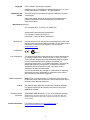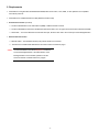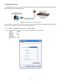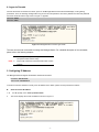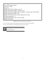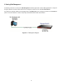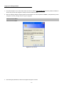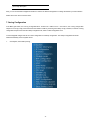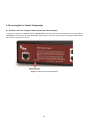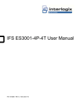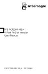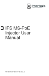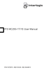
1
NS4702-24P-4S-4X Quick Start Guide P/N 1072831 • REV 00.01 • ISS 14JUL14 Copyright © 2014 United Technologies Corporation Interlogix is part of UTC Building & Industrial Systems, Inc. a unit of United Technologies Corporation. All rights reserved. Trademarks and patents The NS4702-24P-4S-4X name and logo are trademarks of United Technologies. Other trade names used in this document may be trademarks or registered trademarks of the manufacturers or vendors of the respective products. Manufacturer Interlogix 3211 Progress Drive, Lincolnton, NC 28092 USA Authorized EU manufacturing representative: UTC Climate Controls & Security B.V., Kelvinstraat 7, 6003 DH Weert, Netherlands Intended use Certification FCC compliance ACMA compliance Use this product only for the purpose it was designed for; refer to the data sheet and user documentation for details. For the latest product information, contact your local supplier or visit us online at www.interlogix.com. N4131 This equipment has been tested and found to comply with the limits for a Class A digital device, pursuant to part 15 of the FCC Rules. These limits are designed to provide reasonable protection against harmful interference when the equipment is operated in a commercial environment. This equipment generates, uses, and can radiate radio frequency energy and, if not installed and used in accordance with the instruction manual, may cause harmful interference to radio communications. You are cautioned that any changes or modifications not expressly approved by the party responsible for compliance could void the user's authority to operate the equipment. Notice! This is a Class A product. In a domestic environment this product may cause radio interference in which case the user may be required to take adequate measures. Canada This Class A digital apparatus complies with Canadian ICES-003. Cet appareil numérique de la classe A est conforme á la norme NMB-003du Canada. European Union directives 2004/108/EC (EMC Directive): Hereby, UTC Building & Industrial Systems, Inc. declares that this device is in compliance with the essential requirements and other relevant provisions of Directive 2004/108/EC. Contact Information For contact information, see www.interlogix.com or www.utcfssecurityproducts.eu. -2- Table of Contents 1. PACKAGE CONTENTS ................................................................................................................................................ 4 2. REQUIREMENTS.......................................................................................................................................................... 5 3. TERMINAL CONNECTION........................................................................................................................................... 6 4. LOGON TO CONSOLE................................................................................................................................................. 7 5. CONFIGURING IP ADDRESS ...................................................................................................................................... 7 6. STARTING WEB MANAGEMENT.............................................................................................................................. 10 7. SAVING CONFIGURATION........................................................................................................................................ 13 8. RECOVERING BACK TO DEFAULT CONFIGURATION .......................................................................................... 15 9. CUSTOMER SUPPORT.............................................................................................................................................. 16 -3- 1. Package Contents Thank you for purchasing NS4702-24P-4S-4X , L2+ 24-Port 10/100/1000Mbps 802.3at PoE + 4-Port 10G SFP+ Managed Switch with Hardware Layer3 IPv4/IPv6 Static Routing, NS4702-24P-4S-4X. “Managed Switch” mentioned in this Guide refers to the NS4702-24P-4S-4X. Open the box of the Managed Switch and carefully unpack it. The box should contain the following items: The NS4702-24P-4S-4X Managed Switch x 1 User's Manual CD x 1 Quick Installation Guide x 1 RJ-45 to RS232 Cable x 1 Rubber Feet x 4 Two Rack-mounting Brackets with Attachment Screws x 1 Power Cord x 1 SFP Dust Cap x 8 If any item is found missing or damaged, please contact your local reseller for replacement. -4- 2. Requirements Workstations running Windows XP/2003/Vista/7/8/2008, MAC OS X or later, Linux, UNIX, or other platforms are compatible with TCP/IP protocols. Workstations are installed with Ethernet NIC (Network Interface Card) Serial Port Connection (Terminal) The above Workstations come with COM Port (DB9) or USB-to-RS-232 converter. The above Workstations have been installed with terminal emulator, such as Hyper Terminal included in Windows XP/2003. Serial cable -- one end is attached to the RS-232 serial port, while the other end to the console port of the Managed Switch. Ethernet Port Connection Network cables -- Use standard network (UTP) cables with RJ-45 connectors. The above PC is installed with Web Browser and JAVA runtime environment plug-in. Note: It is recommended to use Internet Explore 8.0 or above to access the Managed Switch. If the Web interface of the Managed Switch is not accessible, please turn off the anti-virus software or firewall and then try it again. -5- 3. Terminal Connection To configure the system, connect a serial cable to a COM port on a PC or notebook computer and to RJ-45 type of serial (console) port of the Managed Switch. Figure 3-1 Managed Switch Console Connectivity A terminal program is required to make the software connection to the Managed Switch. Windows' Hyper Terminal program may be a good choice. The Hyper Terminal can be accessed from the Start menu. 1. Click 2. START, then Programs, Accessories and then Hyper Terminal. When the following screen appears, make sure that the COM port should be configured as: Baud : 115200 Data bits :8 Parity : None Stop bits :1 Flow control : None Figure 3-2 Hyper Terminal COM Port Configuration -6- 4. Logon to Console Once the terminal is connected to the device, power on the Managed Switch and the terminal will display “running testing procedures”. Then, the following message asks to log-in user name and password. The factory default user name and password are shown as follows and the login screen in Figure 4-1 appears. Username: admin Password: admin Figure 4-1: Managed Switch Console Login Screen The user can now enter commands to manage the Managed Switch. For a detailed description of the commands, please refer to the following chapters. Note: 1. For security reason, please change and memorize the 2. Only accept command in lowercase letter under console new password after this first setup. interface. 5. Configuring IP Address The Managed Switch is shipped with default IP address shown below. IP Address: 192.168.0.100 Subnet Mask: 255.255.255.0 To check the current IP address or modify a new IP address for the Switch, please use the procedures as follows: 1. At 2. Show the current IP Address the “#” prompt, enter “show ip interface brief”. The screen displays the current IP address as shown in Figure 5-1. -7- Figure 5-1: IP Information Screen Configuring IP Address 3. At the “#” prompt, enter the following command and press <Enter> as shown in Figure 5-2. NS4702‐24P‐4S‐4X# configure terminal NS4702‐24P‐4S‐4X(config)# interface vlan 1 NS4702‐24P‐4S‐4X(config‐if‐vlan)# ip address 192.168.1.100 255.255.255. The previous command would apply the following settings for the Managed Switch. IP Address: 192.168.1.100 Subnet Mask: 255.255.255.0 Figure 5-2: Configuring IP Address Screen 4. Repeat step 1 to check if the IP address is changed. Store current switch configuration 5. At the “#” prompt, enter the following command and press <Enter>. # copy running-config startup-config -8- Figure 5-3: Saving Current Configuration Command Screen If the IP is successfully configured, the Managed Switch will apply the new IP address setting immediately. You can access the Web interface of the Managed Switch through the new IP address. If you are not familiar with the console command or the related p arameter, enter “help” anytime in con sole to get the help description. -9- 6. Starting Web Management The follo wing shows how t o start up the Web Management of the Man aged S witch. Note the Man aged S witch is config ured through an Ethernet connection. Please make sure the manager PC must be set on the same IP subnet address. For example, the default IP address of the Managed Switch is 192.168.0.100, then the manager PC should be set at 192.168.0.x (where x is a number between 1 and 254, except 100), and the default subnet mask is 255.255.255.0. Figure 6-1: IP Management Diagram - 10 - Logging in the Managed Switch 1. Use Internet Explorer 8.0 or above Web browser and enter IP address http://192.168.0.100 (the factory default IP address or the one that you have just changed in console) to access the Web interface. 2. When the following dialog box appears, please enter the default user name and password “admin” (or the password you have changed via console). The login screen in Figure 6-2 appears. Default Username: admin Default Password: admin Figure 6-2: Login Screen 3. After entering the password, the main screen appears as Figure 6-3 shows. -11- Figure 6-3: Web Main Screen of Managed Switch The Switch Menu on the left of the Web page let you access all the commands and statistics the Managed Switch provides. Figure 6-4: Switch Menu Note: If you are not familiar with Switch functions or the related parameter, press “Help icon” anytime on the Web page to - 12 - get the help description. Now, you can use the Web management interface to continue the Switch management or manage the Switch by console interface. Please refer to the user’s manual for more. 7. Saving Configuration In the Mana ged S witch, the runni ng co nfiguration file is stored in the RAM. In the cu rrent versi on, the r unning configur ation sequence of ru nning-config can be saved from the R AM to FLASH by executing save startup config command, so that the run ning configuration sequence becomes the startup configuration file, which is called configuration save. To save all applied changes and set the current configuration as a startup configuration. The startup-configuration file will be loaded automatically across a system reboot. 1. Click System, Save Startup Config. - 13 - 2. Press the “Save Configuration” button. - 14 - 8. Recovering Back to Default Configuration IP Address has been changed or admin password has been forgotten – To reset the IP address to the default IP Address “192.168.0.100” or reset the login password to default value, press the hardware reset button on the front panel for about 10 seconds. After the device is rebo oted, you can login the management WEB interface within the same subnet of 192.168.0.xx. Figure 8-1: NS4702-24P-4S-4X Reset Button -15- 9. Customer Support Thank you for purchasing INTERLOGIX products. You can browse our online FAQ resource on the INTERLOGIX website first to check if it could solve your issue. If you need more support information, please contact INTERLOGIX.com/support for the support team. www.interlogix.com/customer support - 16 -