1
DUETTO 125
IT
USO E MANUTENZIONE
EN USE AND MAINTENANCE
DE GEBRAUCH UND WARTUNG
FR EMPLOI ET ENTRETIEN
ES EMPLEO Y MANTENIMIENTO
Cod. B0D6P0043
2014-09
*)
*) Valido per Paesi UE
*) Valid for EU member countries
*) Valable dans les Pays UE
*) Gilt für EU-Mitgliedsländer
*) Válido para Países UE
DUETTO 125
SUMMARY
1_INTRODUCTORY INFORMATION .................................................................... 2
2_TECHNICAL DATA .............................................................................................. 6
3_GENERAL SAFETY PRESCRIPTIONS ............................................................ 11
4_HANDLING AND TRANSPORT ......................................................................... 25
5_INSTRUCTIONS FOR USE ................................................................................. 28
6_OPERATION ......................................................................................................... 43
7_MAINTENANCE, LUBRICATION AND CLEANING ....................................... 48
8_CONTROL UNITS ................................................................................................ 77
9_TABLES, DIAGRAMS AND ENCLOSURES.................................................... 123
10_TROUBLESHOOTNG ........................................................................................ 129
11_ACCESSORIES AND KITS (OPTIONAL) ...................................................... 134
12_DISPOSAL .......................................................................................................... 135
INTRODUCTION
Dear Customer,
Congratulations on choosing a FERABOLI product!
Compliance with all the instructions contained in this “Operating and Maintenance Manual” will result in maximum safety, excellent performance and long operating life.
1
DUETTO 125
1_INTRODUCTORY INFORMATION
1.1_IDENTIFICATION OF MACHINE AND MANUAL
The Round Baler with Bale Wrapper is supplied with:
Operator manual
CE Declaration of Conformity
Instruction handbook of the Cardan shaft
Every machine is also provided with an identification plate showing:
Name and address of the manufacturer
“TYPE” = model of the machine
“N°.” = serial number
“Weight kg” = weight of the machine
Machine Designation
Year of manufacture
“CE” marking
The information shown on the identification plate of the machine must always be quoted in any request for spare parts and/or assistance.
Copy the machine information into the plate reproduced on the back of the cover for ease of consultation.
2
DUETTO 125
1.2_CERTIFICATION
The Round Baler “DUETTO 125” is a machine with "CE" marking in compliance with the standards of the European Union described in
2006/42/CE Directive and 2004/108/CE Directive (Electromagnetic Compatibility), as shown in the “CE Declaration of Conformity” provided with
every machine.
FERABOLI S.p.A. disclaims all liability arising from use of the machine on products that do
not comply with European standards.
If the machine should be sold to a third party, the declaration of conformity must be handed over together with it.
1.3_WARRANTY CONDITIONS
Please refer to the general conditions enclosed with the purchase contract of the machine.
3
DUETTO 125
1.4_GENERAL REGULATIONS
The user must ensure that personnel in charge of using the machine are also informed of the following subjects concerning safety devices:
Risk of injury
Devices provided for the operator’s safety
General accident-prevention regulations and those envisaged by international directives and legislation in the machine’s Country of destination
Maintenance and cleaning staff must strictly observe the accident prevention regulations in the machine’s Country of destination.
CAUTION!:
- Before starting work the operator should be familiar with the machine’s characteristics and
have read this entire manual.
- Carefully read all sections of the operator manual. If some parts are not clear contact your
FERABOLI dealer or our Assistance Centre at the addresses shown on the last page of this
manual.
- The instructions, warnings and general accident prevention regulations contained herein
and in relative enclosures must be strictly observed.
1.5_OPERATOR REQUIREMENTS AND LANGUAGE USED
To understand the instructions (text and illustrations) the operators must have (or must acquire by
suitable education and training) the following:
A sufficient level of general and technical education to read and understand the contents of the
manual and to correctly understand drawings and diagrams.
Ability to understand and follow symbols, pictograms and video messages.
Familiarity with the main hygiene, accident-prevention and technological standards.
Comprehensive knowledge of the machine.
Familiarity with procedures to follow in an emergency, where to find personal protective equipment
and how to use it correctly.
Operators must be experienced in the type of work for which the machine has been constructed.
CAUTION!:
- Maintenance staff, in addition to the previous requirements, must be well trained technically as certified by professional qualifications and/or appropriate experience in their field of work.
- They must furthermore have the technical, specific and specialist knowledge (mechanical, electrical) required for the
tasks specified in the manual.
4
DUETTO 125
1.6_KEEPING THE MANUAL
Keep this manual and all the attached documents in a place that is easily accessible and known to all
users (operators and maintenance personnel).
Operators and maintenance staff must be able to find and consult the manual and attachments rapidly in any situation.
WARNING!
The manual is an integral part of the machine with which it has been supplied.
Therefore:
it must be kept complete (in all its parts) without any modification to any of its pages in the form of
corrections, erasures, abrasions or anything that prevents easy reading of the manual;
it must accompany the machine until it is scrapped (also in the case of transfers, sale, hire, rent,
etc.);
it must be kept available for anyone who has to use the machine;
If the user manual becomes damaged or is lost, request a copy from the Spare Parts Department at FERABOLI S.p.A., stating the manual code or, if unavailable, the data printed on the
metal data plate on the machine.
At the beginning of each season, before starting up the machine re-read and bear in mind the instructions for use and the safety regulations contained herein.
Read the entire operating manual carefully. If any points are unclear please contact your FERABOLI S.p.A. Dealer or the FERABOLI S.p.A. Service Centre. The relative addresses are given on the front cover.
1.7_ENVISAGED USE
This machine has been manufactured exclusively for the gathering, pressing and wrapping into cylindrical bales of hay, semi-dried forage, grass, straw.
A single operator in the tractor can carry out all various operations.
Any other type of use is considered unsuitable for the machine.
The operating, maintenance and repair instructions - as this manual sets forth - shall be complied
with and strictly abided by, as they are essential to ensure the machine is used correctly.
Any such unsuitable use, or use not covered by this manual, releases FERABOLI S.p.A. of all and
every liability for damage to persons, animals or things.
1.8_GENERAL NOTES ON DELIVERY
Upon delivery of the machine, check that:
The supply corresponds to the specifications stated in the purchase order.
There is no damage to the machine or to its accessories.
In case of damages or missing parts, notify FERABOLI S.p.A. or its local representatives, the shipper or his insurance company immediately and in detail and/or with photographs.
1.9_ORDERING SPARE PARTS
When the instance arises, always use original spare parts. Always contact your FERABOLI S.p.A.
Dealer or the FERABOLI S.p.A. Spare Parts Department.
5
DUETTO 125
2_TECHNICAL DATA
2.1_TECHNICAL DATA OF THE MACHINE
The technical data contained in the tables are informative and therefore we reserve the right
to update them without giving prior notice.
All measurements are expressed in millimetres (mm).
All weights are expressed in kilograms (kg).
The symbol “” indicates a value lying between a minimum and a maximum.
2.1.1_DIMENSIONS AND WEIGHTS
Here follows a list of the technical characteristics of the Bale Wrapper and of the Round Baler.
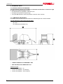
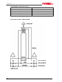
The main dimensions of the machine are given below:
A = 6200
B = 2550
H = 2900 (with tyres 400/60-15.5)
OVERALL WEIGTH OF THE MACHINE = 4980
MAX. VALUE ON THE TOWING EYE = 470
Additional weights:
Cardan shaft 3600087 = 29
Cardan shaft 3600092 = 36 (TOPCUT)
Cardan shaft 3600093 = 36 (ULTRACUT)
6
DUETTO 125
2.1.2_PICK-UP AND CUT UNIT
PICK-UP
PICK-UP 200
PICK-UP 220
Max. harvest width
1725
2000
Width between tines
1593
1869
Tine spacing
69
Reel-holder diameter
250
N°. bars/reel-holder
4
N°. tines/bar
24
28
Overall number of tines
96
112
Support wheels
Fixed
Dimensions of wheels/n. of plies
16.650x8/10
Adjustment of work height
Mechanical
CUT UNIT
TOPCUT
ULTRACUT
Number of knives
13
25
Pitch between knives
77
45
Knife control
Electric
Knife protection device
Single, with a spring
Feed rotor
Three-pointed stars
2.1.3_TWINE AND NET TYING
TWINE
Twine binder
NET
Double twine
Twine runnage
500÷1000
Twine rolls
2+2
Net reel diameter
250÷300 mm
Net runnage
12÷16 g/m
Control
Max. number of reels that can be transported
electronic
electronic
4
2
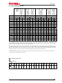
2.1.4_TYRES
Series:
Optional:
N. of plies
Radius (mm)
Speed
(km/h)
Wheel capacity (Kg)
Pressure
(bar)
Outside
diameter (mm)
10-14 P.R.
380
40
2240÷2745
2,5÷3,5
875
380/55-17
10 P.R.
395
40
2800
3,40
850
19.0/45-17
10-14 P.R.
390
40
2124÷2800
2,25÷4,0
850
400/60-15.5
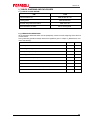
2.1.5_CARDAN SHAFTS
TOPCUT
Series:
Optional:
ULTRACUT
3600087 BYPY 656 (OC+SB6)
3600092 BYPY 656 (OC+LR 2500Nm)
3600093 BYPY 656 (omo+LR 2900Nm)
7
DUETTO 125
2.1.6_TRACTOR REQUIREMENTS*
TOPCUT
PTO r.p.m.
Minimum power kw-cv
ULTRACUT
540 r.p.m.
75 / 102
81 / 110
Hydraulic system
n°.1 double-acting distributor + n°.1 single-acting distributor
Oil flow necessary
25 liters/1’
Electric system
12V = / negative earth
Max. road speed
40km/h
(*)with tractor provided with cabin
If a tractor without cabin is used, ask the FERABOLI company for the special kit “ZMP2015 – Protection of hydraulic tubes”.
2.1.7_FEATURES OF THE BALES
TOPCUT
ULTRACUT
Diameter
1200
Width
1218
Weight of hay bale
280
Weight of straw bale
205
Weight of green bale
400÷880
Hourly production
25÷55
2.1.9_STANDARD DEVICES
Road lights
Multiple electronic bale counter
Electronic control unit
Automatic chain lubrication device
Tyres (upon request)
Note: the technical data contained in the following tables are informative therefore we reserve the right
to update and modify them without obligation to give prior notice.
8
DUETTO 125
2.2_TECHNICAL DATA OF THE BALE WRAPPER
Length
4,2m
Width
2,6m (A)
Recommended bale diameter
Ø1,0 ÷ 1,5m
Max. weight of bale
1200kg / 150bar
Film tensioners
2x750/500mm
Wheel dimensions
26.00x12-12
Weight
~1150kg
Standard equipment:
Rear light kit
Electric valve with proportional control
Bale side support rollers, 4 pcs.
Hydraulic loading arm
N° 2 x 750/500mm film pre-tensioners
Film cutters
JD conversion valve (for closed centre hydraulic system).
Optional equipment:
Bale drop mat
Connections:
Recommended hydraulic connection for the wrapper
Continuous oil flow
Free return line and pressure range
Recommended electric connection for the wrapper
Voltage
Fuse
min. 20 liters/
max. 30 liters/1’
150÷200 bar
12V
(battery fed; 4mm² wires recommended)
16A
Note: The technical data contained in the following tables are informative therefore we reserve the right
to update and modify them without giving prior notice.
9
DUETTO 125
2.3_GENERAL DESCRIPTION
The machine carries out the following operations:
Harvest of the forage already in swathes
Cylindrical-shaped bailing (bale)
Bale tying
Bale wrapping
Ejection onto the ground
The machine is made up of a structure mounted on the frame fitted with all the processing mechanisms; it is supported by two axles with wheels for the transfer function and is equipped with a drawbar with hitch to attach to the tractor.
The electrical system controls the control units and the road lights for road transport.
The hydraulic system is activated by connecting the machine connection pipes to single-acting and
double-acting outlets located on the tractor.
A cardan shaft connected to the tractor and to the transmission box located on the machine, transmits motion to the machine parts.
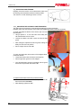
The main components of the machine are as follows:
1) Drawbar
2) Parking jack or support leg
3) Cardan shaft
4) Transmission box
5) Net wrapper
6) Twine binder
7) Rollers
8) Tailgate
9) Pick-up
10
10) “EasyTronic” control unit
11) Reflex reflectors
12) Plastic film unwinder
13) Bale wrapper structure
14) Pre-tensioners
15) Bale ejector
16) Bale wrapper control unit
17) Lights system for road transport
DUETTO 125
3_GENERAL SAFETY PRESCRIPTIONS
3.1_SYMBOLS USED AND DEFINITION
Here follows a list and description of the main symbols used in this manual.
CAUTION!: ELECTROCUTION HAZARD
It warns the personnel in charge against possible risks of injuries or damages to persons due
to electric shock, in case the operation described is not carried out in compliance with the
safety prescriptions.
CAUTION!: GENERAL HAZARD
It warns the operator in charge against possible risks of injuries or damages in case the operation described is not carried out in compliance with the safety prescriptions.
WARNING!
It warns the personnel in charge against possible machine damages in case some prescriptions are
not observed.
This is a warning sign for the operator; it requests the operator to turn off
the tractor and to remove the key from the dashboard.
Wherever you find this symbol in this operator manual, you must always turn off the tractor and remove the keys from the dashboard before carrying out the operations described.
FERABOLI S.p.A. disclaims any and all liability resulting from failure to observe these safety
warnings.
Please refer to the page in the instruction manual.
Please refer to the Spare Parts Catalogue.
EXTRAORDINARY MAINTENANCE
The manufacturer’s assistance service must be asked to perform any of the special maintenance
tasks that are marked by the symbol at the side.
OPERATOR OR MACHINE OPERATOR
Identifies staff specifically trained to run the machine under normal conditions.
The operator must under no account perform tasks that are the responsibility of the maintenance
technician.
MECHANICAL MAINTENANCE TECHNICIAN
Qualified technician who is able to run the machine under normal conditions and to work on mechanical parts in order to adjust, maintain and repair them as required. He is not qualified to work on electrical parts carrying live voltage.
11
DUETTO 125
DEFINITION OF DANGER AREA
As described in Directive 98/37, annex 1, paragraph 1.1.1.
Area inside and/or in proximity to the machine in which the presence of a person exposed constitutes
a risk or danger for the health and safety of the said person.
These residual risk areas are identified by DANGER notices.
DEFINITION OF DANGEROUS SITUATION
As described in regulation EN 292/1, section 3.6.
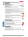
The operator must wear suitable safety gloves for the task in hand.
Any situation in which a person is exposed to danger.
Obligation on the part of the operator to wear safety gloves
Obligation on the part of the operator to wear heavy-duty work boots
Obligation on the part of the operator to wear a safety helmet
Obligation on the part of the operator to wear ear-defenders
Obligation on the part of the operator to wear goggles
FERABOLI S.p.A. disclaims any and all liability resulting from failure to observe these safety
warnings.
12
DUETTO 125
3.2_GENERAL SAFETY PRESCRIPTIONS
In addition to the rules contained in this operator’s manual, observe the general regulations for safety
and accident prevention in force in the Country where the machine will be used.
This machine has been designed and manufactured for the maximum safety at work. Maintenance of
these safety conditions is obligatory for the user.
Before using this machine for the first time, read carefully all the chapters of this manual: reading it
when the machine is already in operation would be useless!
FERABOLI S.p.A. declines all responsibility for failure to observe the safety regulations and
precautions given in this manual.
FERABOLI S.p.A. also declines all liability for damage caused by improper use of the round
baler or unauthorised modifications.
3.2.1_RULES FOR THE USER
Before any adjustment, maintenance or service to the machine and before you leave it unattended,
the following rules shall be abided by:
Make sure that you are perfectly familiar with the controls and their functions, particularly with the
Bale Wrapper and Round Baler control units.
Perform regular checks on the soundness of the entire machine: all the safety devices and guards.
All the safety guards should be assembled and secured as per the manufacturer’s instructions,
and should never be tampered with.
CAUTION!:
It is absolutely forbidden for the machine to be used by persons who have not read and assimilated the contents of this manual.
Never use the machine without the guards.
Safety guards must be installed and secured according to the manufacturer’s directions and must
not be tampered with; the operator must refit the guards after any machine maintenance.
Never climb aboard and never allow anyone to climb aboard the machine whilst it is working. This
is extremely dangerous and may result in death or serious injury if the person falls.
Do not allow anyone to go near the machine while it is running or during work operations. Keep
the rotating knives at a safe distance, since they can cause serious injury or even death.
Keep unauthorised persons off the danger areas - around tractor or machine - and make sure they
stay at a safe distance.
Operate the controls only from the tractor driver’s seat! Make sure nobody is next to the machine
and to its movable equipment.
Never leave the tractor unattended with its engine running!
Before leaving the tractor, turn it off, remove the key and engage the hand brake.
Before starting the tractor engine make sure nobody is next to the machine.
TRACTORS MUST BE FITTED WITH CABS.
IF TRACTORS WITHOUT CABS ARE USED CONTACT THE FERABOLI S.p.A. ASSISTANCE
CENTRE TO ARRANGE TO HAVE A GUARD FITTED ON THE HYDRAULIC PIPING.
The envisaged use of the machine is the harvesting and baling of forage and its subsequent
wrapping in plastic film and dumping onto the ground. All other types of use are considered improper.
The machine should always only be used by persons who have a working knowledge of it.
Stop the tractor before making any adjustments, carrying out maintenance operations or loading
materials.
Do not use the automatic bale unloading cycle by means of the bale wrapper control unit unless
you are absolutely certain that it is safe to do so.
For road travel find out about local transport regulations, particularly with regard to light sizes and
danger notices.
13
DUETTO 125
3.2.2_NOTICES
Take note of the danger symbols in this manual and on the machine itself. Adhesive danger notices
should always be clearly visible. Make sure that they are always kept clean and replace them if they
become damaged or illegible. The positions and list of all the danger symbols are given in section “3.3
Accident-prevention notices”.
CAUTION! NOTICE!
Do not allow the machine to be used by minors or persons who are not competent, or not in good
health or who do not have a valid driving license.
The radius of action of the machine is to be considered a dangerous area: before
putting the machine into operation make sure that there are no persons or animals
around the work area, otherwise stop the machine and clear the area.
The person using the machine is liable towards third parties for any damage caused
by the machine inside the radius of action.
During operation of the machine it is absolutely forbidden to approach the mechanical parts, touch
the moving parts or interpose oneself between them. Keep your face, hands and feet away from moving parts; stay at a safe distance.
Do not stand behind the machine, the bale wrapper can offload the bale.
The area in front of the machine is very dangerous; when the machine is in operation, never insert the forage using the hands, feet or the help of any other object.
If the product should block the feed area: turn off the tractor, remove the keys from the dashboard
and follow the instructions given in paragraph “7.7_Unblockage of the product”.
Load the twine or net wrap only with the tractor engine off, and after cutting off the current to the
control unit.
Do not use the controls, tubes and other protruding parts of the machine to hang things on.
Assemble, operate and detach the cardan shaft always respecting the information and safety rules
for use of the cardan shaft contained in the booklet provided by the manufacturer of the cardan
shaft and delivered together with it.
It is absolutely forbidden to transport persons or animals on the machine or tractor.
During maintenance and/or repair work it is obligatory to wear protective clothing, cut resistant
gloves, safety footwear and goggles; do not wear clothes that could get caught on the moving
parts. If there is a risk of objects being thrown out, wear a protective helmet fitted with a visor.
For further information consult the paragraph “3.2.5_Personal protective equipment”.
Take great care to maintain a minimum safety distance when working in the vicinity
of electrical transmission lines; the machine is made mainly of metal and therefore if
it comes into contact with an electrical line or if there is a discharge between the line
and the machine the operator could be electrocuted with possible fatal consequences.
If it is necessary to operate in the vicinity of electrical transmission lines contact the
competent electricity company.
Unload the bales on flat ground or in a suitable position if the ground is sloping.
High pressure hydraulic oil can penetrate the skin and cause serious injury. Before detaching any tubes or doing any checks the system should always be depressurised. If
any hydraulic oil under pressure should penetrate the skin immediately apply to a firstaid medical centre or hospital otherwise the risk of serious infections could be run.
FERABOLI S.p.A. declines all liability resulting from failure to observe these safety warnings.
14
DUETTO 125
3.2.3_WARNINGS FOR THE MACHINE
CAUTION! NOTICE!
The hydraulic couplings shall always be kept clean. To prevent them from becoming dirty or damaged, after use always refit the protective plastic covers provided at the time of purchase. Check
and if necessary replace any damaged tubes or fittings; all flexible hoses should be replaced in
any case five years after the date stamped on the hose.
Before re-pressurising the system check that the tubes and connections are tight; use a piece of
cardboard or absorbent paper to check for possible leaks.
Each cardan shaft is provided with an operating and maintenance manual supplied by the manufacturer of the cardan shaft. The protections of the cardan shaft, tubes and covers, must be
mounted and in perfect condition.
Maintenance work on the cardan shaft must be done scrupulously following the instructions given
in the booklet supplied together with the cardan shaft by the manufacturer.
Before engaging the PTO make sure that:
the number of rpm corresponds to the required number (refer to the decal located on the
drawbar of the machine.
the direction of rotation is the same as that indicated by the adhesive safety sign.
NEVER engage the PTO before starting up the tractor’s engine.
Stop the PTO during the turns at the end of the swath and any other tight turns.
When the machine is detached from the tractor position the cardan shaft on the special support.
Never start a bale if the tailgate is not completely closed; check this condition also on the display of
the control unit.
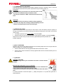
CAUTION! FIRE RISK
Remove the accumulated product regularly to reduce the risk of fire and to prevent material from winding around the mechanical parts of the machine.
If the bale should catch fire:
1) Immediately expel the bale and keep the tailgate open.
2) Move the tractor and machine away from the product still to be collected and any
other inflammable material.
3) Put the fire out using the extinguisher, advised as part of your equipment.
There must always be an extinguisher on the tractor, especially if you are working on a
dry product.
Repairs to the wheels and tyres must be done by competent specialised personnel
having the appropriate tools.
The machine is not equipped with a lighting system in the operative area. It is best to use portable
lamps for cleaning, lubricating and maintenance operations.
INSTALLATION AND COMMISSIONING OF THE MACHINE IN PLACES OR AREAS WHERE
THERE IS A RISK OF FIRE AND/OR EXPLOSION IS STRICTLY PROHIBITED.
For all handling operations of the machine at the time of delivery, and when unhitching from the tractor please refer to chapter “4_Handling and Transport” in this manual.
Never lift the machine or parts of the machine by its chassis or any of its projecting parts.
Use the recommended lifting devices, always ensuring that the maximum capacities of the said lifting
devices are suitable for the weight of the machine.
Always remember to refit all guards and reassemble and/or close any parts removed
during cleaning, lubricating and maintenance operations.
When replacing worn and/or broken parts only use original FERABOLI S.p.A. spare
parts.
Should any problems arise during operation, stop the tractor immediately and investigate the cause of the fault.
15
DUETTO 125
3.2.4_SAFE MAINTENANCE
CAUTION! IMPORTANT!
Before any adjustment, maintenance or service to the machine and before you leave it unattended,
the following rules shall be abided by:
- Stop the machine and disengage the PTO.
- Lay the Pick-up on the ground.
- Turn off the tractor’s engine and remove the keys from the dashboard;
engage the hand brake.
- Cut off power to the control units.
- Check and wait until every moving part has completely stopped.
It is absolutely forbidden to remove or tamper with the safety devices because these have been
designed and installed for your protection and safeguard. If they should get damaged replace
them before using the round baler again.
Check frequently that the nuts, screws and bolts are correctly tightened.
Check frequently and regularly the state of wear of the bearings, rollers, chains and gears.
Do not carry out any maintenance or cleaning work if the tractor has not been turned off first and
the keys removed from the dashboard; remove any dirt that might have accumulated from all the
moving parts of the machine.
Do not use high pressure jets for cleaning the machine; this may cause serious
damage to the mechanical parts.
Take careful note of the precautions to be taken for welding work; detach the machine from the tractor, remove any residual forage and make sure that there are no
plastic materials nearby in order to avoid fire risk; it would be advisable to have a
fire extinguisher at hand just in case.
Use the oils advised.
Carry out the maintenance scrupulously according to this manual and have worn or
damaged parts replaced by specialised personnel.
USE ORIGINAL SPARE PARTS ONLY
Spare parts must correspond to the requirements established by the manufacturer.
Use only the cardan shafts indicated by the manufacturer of the machine.
3.2.5_PERSONAL PROTECTIVE EQUIPMENT
Setting up, cleaning and maintenance operations shall be carried out by only ONE person.
NEVER BY MORE THAN ONE PERSON
(unless instructions are given to the contrary)
Personal protective equipment, such as protective goggles, burn-proof and cut-proof
gauntlets and safety industrial boots shall be always available and wear them as needed.
It is moreover recommended to:
wear working overalls with close-fitting sleeves
gather or bind your hair, it is too long
never wear loose and/or torn objects or items of clothing (necklaces, watches,
rings, bracelets, scarves, ties, etc.).
Staff involved in the maintenance, adjustment and handling of the machine at the time
of delivery and when unhitched from the tractor should always wear goggles, safety
gloves, heavy-duty footwear and a safety helmet.
16
DUETTO 125
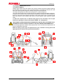
3.3_ACCIDENT-PREVENTION NOTICES
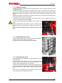
3.3.1_SAFETY SIGNALS
Adhesive signs (decals) have been affixed to the machine containing important messages regarding
personal safety. Their purpose is to call the operators attention to the health and safety at work rules
and to warn against possible dangerous situations during work and maintenance.
The safety signs typically have black and red pictograms on a yellow background.
They must always be kept clean and legible and must be replaced whenever damaged or peeling off.
If the parts of the machine to which they are affixed are replaced or painted they must be replaced as
before. For this purpose each adhesive sign bears a code number so that it may be ordered from the
Spare Parts Service. Ask the Spare Parts Service for these adhesive signs quoting the relative
codes.
To obtain the complete series of adhesive safety signs for the round baler, ask our spare
Parts Service quoting the relevant code number 7Z00659. “CE - Safety decals”.
THESE SIGNS OR INDICATIONS MUST BE RESPECTED, OBEYED AND IN THE EVENT OF DETERIORATION OR ANY FORM OF ILLEGIBILITY THEY MUST BE REPLACED IMMEDIATELY.
In the following pages all the adhesive safety signs present on the round baler and represented in the
figure are illustrated and described.
Read the meaning of the signs and explain them to your co-workers and any person that
might approach the machine during work and maintenance.
16
4
7
13
12
7
18
5
5
7
11
10
1
14
10
8
15
2
4
7
1
6
6
9
3
10
11
17
DUETTO 125
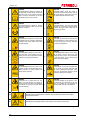
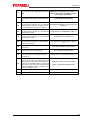
1
3
5
7
9
11
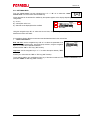
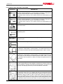
7500185
7500186
CAUTION! Before putting into service, at
the beginning of each season and before
doing any work on the machine, read and
bear in mind the instructions for use and
maintenance given in this manual.
CAUTION! Before doing any repair or
maintenance work on the machine, turn off
the tractor engine, remove the keys from
the dashboard and read this manual.
2
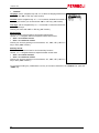
7500187
7500724
CAUTION! Machine suitable for tractors
with power take-off at 540 rpm and one
direction of rotation.
CAUTION! Before you enter the baling
chamber for any reason lock the hydraulic
cylinders with their proper safety locks to
avoid being crushed.
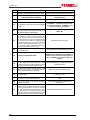
4
7500198
7500199
CAUTION! Do not pass by or stand under
the tailgate when it is raised to avoid being
crushed if the special safety locks have
not been applied.
CAUTION! Do not enter the manoeuvring
space between the machine and the tractor when the engine is running. This area
is particularly dangerous.
6
7500203
7500207
CAUTION! Before doing any work wait until all the parts of the machine are completely still and use appropriate methods
to block any undesired movements.
ATTENTION! Never feed or remove material by hand in front of the pick-up unit
when parts are in motion. This could result
in the upper limbs, or more seriously the
person, becoming trapped.
8
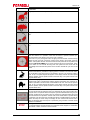
7500208
7500210
CAUTION! Before doing any work on the
hydraulic system consult and read the operating manual. Oil under pressure can
cause serious infections.
CAUTION! Do not remove the guards and
do not come into contact with parts that
can cause crushing of upper limbs, some
parts may still have the capacity to move
suddenly under their own weight.
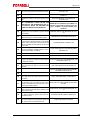
10
7500221
7500200
CAUTION! Do not stand near the machine. This could result in the crushing or
cutting of lower limbs due to the weight of
the machine or lowering of its parts. Keep
at a safe distance.
CAUTION! Objects can be thrown in various directions and distances by the machine in operation as it is impossible to
mount guards. Keep at a safe distance.
17
7500197
12
CAUTION! Never stand behind the machine so as to avoid being crushed due to sudden
movements/manoeuvres.
7500201
13
18
CAUTION! Pay the greatest attention when working close to electric power lines.
DUETTO 125
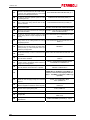
7500212
14
CAUTION! Never stay behind the machine when a bale is ejected. Always keep at a safe distance.
7500781
15
CAUTION! Danger of getting caught and being dragged by the cardan shaft.
7500234
16
CAUTION!. Never get onto the machine while it is working. Those who do so risk their lives
because it is very easy to lose balance and fall among the tools and working parts.
REFLECTORS
Two types of reflex reflectors are located on the machine so that it can
be seen more clearly during road transport:
R) Round reflectors (front on right side and left side)
T) Triangular reflectors (rear).
CARDAN SHAFT DECAL
An adhesive sign is affixed to the cardan shaft to draw the operator’s attention and remind him/her of the safety rules for using the cardan shaft.
19
DUETTO 125
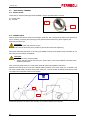
3.4_SAFETY DEVICES
The machine is provided with safety devices in order to ensure a more correct use without risks in
normal working conditions.
CAUTION!:
Before starting work make sure that all the safety devices are intact and in place.
3.4.1_PROTECTION GUARDS
The machine is provided with protection guards to protect the operator from moving mechanical parts
and to protect the mechanical parts from accidental entry of foreign bodies:
1) Front side guard
2) Rear side guard
3) Side guards
4) Protection cover of cardan shaft/transmission box
5) Tailgate rear guard
6) Pick-up guard
7) Pick-up safety guard
8) Big roller guard
9) Guard of cut unit (right side)
10) Bale wrapper gear guard
11) Bale wrapper valve guard
The front side guards are provided with a safety lock that ensures perfect closing of the protection
guard with the machine and thus prevents accidental opening during work or transport.
To open the protection guard a 13mm spanner is required.
CAUTION!:
Before removing any of the protection guards:
Stop the machine.
Turn off the tractor and remove the keys from the tractor dashboard.
20
DUETTO 125
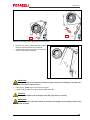
3.4.2_CARDAN SHAFT SAFETY DEVICE
Each cardan shaft is provided with a safety system to protect
the mechanical parts from high starting (pick-up) torques and
maximum twisting moments:
“SB” = with shear bolt.
“LR” = with automatic torque limiter.
3.4.3_PICK-UP TRANSMISSION SAFETY DEVICE
On the pick-up transmission a safety device is mounted
which consists of a shear bolt. It protects against overloads
and foreign matter.
3.4.4_MECHANICAL TRANSMISSION SAFETY DEVICE
FOR CUT UNIT
The drive transmission to the cutter is provided with a shear
bolt which protects against overloads and foreign matter.
3.4.5_ AUTOMATIC TRANSMISSION SAFETY DEVICE
FOR CUT UNIT “AFC”
On machines provided with a cutting device it is possible to
mount an automatic unblocking system “AFC” on the shaft
coming out of the transmission box towards the feed rotor.
This device interrupts power transmission when there is an
overload in order to prevent damage to the machine, the cardan shaft and the tractor.
The “AFC” automatic limiter does the same job as the safety
bolt with the advantage that it does not require the replacement of the sheared bolt and allows the power to be reengaged automatically.
21
DUETTO 125
3.4.6_KNIVES
As protection against the entry of foreign bodies into the
machine (stones, sticks, etc.) that may cause the knives to
break, each knife mounted on a retractable spring system
that allows the knife to lower automatically and then to return automatically to the work position.
3.4.7_KNIFE SECURING SAFETY DEVICE
The handle “M” secures the knives of the cutting system
during operation to prevent them from accidentally entering
the bale forming chamber.
- position “1” = knives secured.
- position “2” = knives free.
3.4.8_CARDAN SHAFT SUPPORT
A) This is for the cardan shaft to rest on when it is not connected to the tractor and thus to protect it from damage.
3.4.9_CARDAN SHAFT SAFETY CHAIN
B) This prevents the rotation of the protection guards of the
cardan shaft during work. Attach it to the drawbar.
3.4.10_SUPPORTS FOR CABLE AND PIPE GUIDE
C) These support hydraulic tubes, electrical cables and wiring cables.
22
DUETTO 125
3.4.11_PARKING DEVICE
This device, placed on the right side of the machine, is used to block the machine and prevent any
accidental movements when not in use and whenever it is necessary to immobilise the machine for
repairs, maintenance or cleaning.
CAUTION!:
The parking brake must always be applied before unhooking the machine from the tractor.
Mechanical parking device:
Move the handle “M” to position “2” to block the machine:
- position “1” = brake free.
- position “2” = brake locked.
Hydraulic parking device:
This device allows the hydraulic brake to be applied
by means of a manual hydraulic pump “P”:
- Open the right side guard and pull out the handle
“M”.
- Insert the handle “M” in the hydraulic pump, and
pump oil in order to apply the brakes.
- When finished, pull out the handle “M” again, replace it and close the guard again.
To release the brake, unscrew the hand-wheel “V”.
3.4.12_TAILGATE SAFETY LOCK
There is a safety device to lock the tailgate in the open
position thus avoiding accidental closing when the operator is inside the machine for maintenance or repair
work.
With the tailgate open, lock the safety cock (valve)
that prevents the tailgate from accidentally lowering.
WARNING!:
Remember to reopen the cock before closing the tailgate so as to avoid serious damage to the structure of
the Round baler.
- position 1 = open
- position 2 = closed
23
DUETTO 125
3.5_SOUND LEVEL
CAUTION!:
Observe the regulations in force in your Country regarding the acoustic protection to be used.
In some circumstances the noise level produced may exceed 85 dbA - 90 dbA. In these cases it is
advisable to use suitable personal protection equipment.
3.6_RESIDUAL RISKS
In spite of the fact that many hazards and risks have been examined and, where possible, the necessary precautions taken to reduce the risks involved during the working phases of the machine,
there still remains a series of residual risks. These are listed below.
Risk of crushing, dragging, shearing, death.
In the instance of contact with the moving parts of the machine during the working
phase:
- IT IS PROHIBITED TO CROSS THE WORKING AREA OF THE MACHINE
DURING OPERATION.
- IT IS PROHIBITED TO CLIMB ABOARD THE MACHINE WHILE ITS PARTS
ARE IN MOTION.
With the parts of the machine during the working phase:
- IT IS PROHIBITED TO CROSS THE WORKING AREA OF THE MACHINE
DURING OPERATION.
- IT IS PROHIBITED TO CLIMB ABOARD THE MACHINE WHILE ITS PARTS
ARE IN MOTION.
Risk of crushing, shear- In the instance of contact with the moving parts of the hydraulic lifting system with
hydraulically operated rear sliding tailgate:
ing, entanglement.
- IT IS PROHIBITED TO STAND WITHIN THE WORKING AREA OF THESE
DEVICES.
Risk of collision.
24
DUETTO 125
4_HANDLING AND TRANSPORT
CAUTION!:
CRUSHING, BLOWING, ABRASION AND CUTTING HAZARD
The personnel in charge of handling machine parts, must have read the safety prescriptions
shown in chapter “3_Safety prescriptions”.
The personnel must moreover wear safety protective gloves, industrial boots and helmet.
CAUTION!:
Never use slings to secure parts of the machine to hoses, frames or projecting shafts.
Check the weight given on the machine’s data plate and check the capacity of the lifting device (see
paragraph 2.1_Technical data).
4.1_LIFTING THE MACHINE
The machine is equipped with attachment points, indicated by special stickers, for aerial lifting using
an overhead device.
Weight with large pick-up = 5020kg
UPON DELIVERY MAKE SURE THAT THE MACHINE IS INTACT, WITH ALL ITS PARTS.
STORE THE MACHINE AND ITS COMPONENTS IN A DRY, COVERED AREA.
Before proceeding with the handling operations make sure that the safety hooks have been correctly inserted at the anchoring points.
Very slowly, only raise the machine slightly from the ground after having made sure that the load
is balanced.
Gently set down on the ground.
4.2_LOADING BY RAMP
The use of ramps to load or unload the machine is not permitted.
25
DUETTO 125
4.3_LOADING WITH A CRANE
CAUTION!:
Before raising the machine make sure that it does not contain any bales.
To raise the machine from the ground to the loading level, if there are no support ramps available,
use a crane of sufficient capacity; make sure that you have a crane and a load equalising arm of suitable capacity for raising the machine.
Use of all points of attachment for correct safe loading is compulsory.
IMPORTANT!:
The attachment points for raising the machine are clearly visible and marked
with special adhesives code 7500216.
Attach the machine only at the points indicated by the adhesive signs to avoid damage.
FERABOLI S.p.A. disclaims all liability arising from damage to the round baler caused by incorrect attachment for lifting.
Raise the machine with extreme care and move it slowly, without jerking, onto the lorry or railway car.
CAUTION!:
Raising and transporting the machine can be very dangerous if not done with the greatest of
care, therefore:
- Make sure that the means available are in good working order and suitable for the load.
- Clear and cordon off the area in which transferral is to take place.
- Make sure that the area in which you are working has been cleared and there is an escape
route, i.e. sufficient space to move out of the way quickly should the load fall.
- Keep onlookers at a distance.
- Do not touch suspended loads and remain at a safe distance.
- During transport the loads must not be raised more than 20 centimetres above the ground.
CAUTION!:
The level on which it is intended to load the machine must be perfectly flat to avoid possible shifting
of the load.
Once the machine has been loaded on the lorry or railway car it is necessary to secure it to the surface on which it stands with cables or chains using the same attachment points and anchoring points
located on the same level and to block the wheels with the parking chocks.
CAUTION!:
Make sure that there are no parts of the machine protruding beyond the maximum overall dimensions permitted by the transport.
After transport and before detaching the machine from all its attachments (constraints), make sure
that its state and position do not constitute a danger.
Then remove the packing and proceed with unloading using the same equipment, methods, attention
and care as in the loading operations.
26
DUETTO 125
4.4_ROAD TRANSPORT
CAUTION!:
Never use the machine as a means of transport for things and/or people.
It is absolutely forbidden to tow the round baler with bales on board and/or rolls of film inserted directly on the pre-tensioners.
Do not operate the round baler when it is being towed.
Disconnect the hydraulic and electrical feed from the bale wrapper before transporting by
road!
The machine must be towed as follows:
Machine unloaded.
All components in position for transport.
All safety devices engaged.
The round baler can be towed on the roads by a tractor at a speed not exceeding 40Km/h.
The machine is hooked onto the rear hook of the tractor using the towing eye attached to the front
drawbar of the round baler with the special towing pin and safety pin.
Avoid circulating on the road with heavy rolls of film inserted directly on the pre-tensioners of the film.
Use the film holders on the mudguard to transport film.
Connect the electrical system and check that all the indicator, parking and stop lights are working
correctly.
Before towing:
Raise the pick-up to the transport position (all the way up) and close the valve (closed position).
Raise the rest foot to the transport position.
Do not connect the quick release couplings of the round baler to the tractor.
During transport the cardan shaft is disconnected from the tractor and must be secured to the drawbar.
If it is necessary to tow the machine over a long distance it may be loaded on a lorry or railway cars.
27
DUETTO 125
5_INSTRUCTIONS FOR USE
5.1_WORK AREAS
Below is a layout showing the areas in which trained drivers of the machine should remain for safety
purposes:
A = tractor control area
B = working area of the machine where access is prohibited during the working phase.
5.2_ENVISAGED USE
The machine compresses the forage, then binds it and offloads a bale onto the ground, obtaining a
finished job in only one pass.
The machine collects the forage already prepared in swathes.
The pick-up can be raised hydraulically and adjusted to the ground. With side aprons and two side
screw feeders, the forage is collected into a swathe 1,20 m wide which corresponds to the bale width.
A pick-up, a “comb” transport component with alternating movement or rotating rotor and shaped rollers guide the forage into the compression chamber. Here the forage is rotated to form cylindrical
bales by rollers driven by chain gears.
Once the compression chamber has been filled to the desired pressure, which can be set to seven
different values, an automatic or manual binding system with double twine, net or plastic film, comes
into action, controlled by the “Bale Tronic” control unit previously installed in the cabin of the tractor.
After tying, the bale is ejected and deposited on the carriage of the bale wrapper which wraps it under
the control of the wrapper control unit.
The wrapper carries out a wrap cycle at the end of which the bale is ejected.
ALL OTHER TYPES OF USE OF THE MACHINE ARE CONSIDERED IMPROPER AND INCORRECT. FERABOLI S.p.A. ACCEPTS NO LIABILITY FOR IMPROPER OR INCORRECT USE OF
THE MACHINE.
28
DUETTO 125
5.3_BEFORE USE
5.3.1_SAFETY RULES BEFORE USE
Mount, operate and disconnect the cardan shaft in compliance with the safety
rules. The cardan shaft connection – on tractor side, is highlighted.
In the case of the hydraulic systems, replace rubber hydraulic hoses after 5 years from the date
printed on the hoses.
Never use controls or hoses as supports.
Before engaging the PTO make sure that the number of revs is as required (540 rpm') and that
the direction of rotation is the same as that which is indicated on the adhesive safety decal.
Never engage the PTO before starting the tractor’s engine.
Stop the PTO during the turns at the end of the swath and any other tight turns.
Make sure you comply with the precautions and provisions for electric
welding. Before welding is carried out disconnect the machine from tractor,
make sure that no plastic materials are near to prevent possible fire.
A fire extinguisher would be advisable to this purpose.
It is better to put the welding gun near the point to be welded to avoid ignition of electrical arcs that
can severely ruin the bearings.
Never use high-pressure water jets to clean the machine as serious damage to mechanical parts may result.
Have only skilled technicians service your machine, using correct tools.
Spare parts must meet the technical requirements set by the constructor of
the machine. These can only be guaranteed by using ORIGINAL SPARE
PARTS.
The use of non-original spare parts will render the warranty void.
When you disconnect the machine from the tractor place the cardan shaft on its support to protect it from possible damage.
Never start a bale if the tailgate is not completely closed.
CAUTION!:
All the above operations must be performed with the tractor engine
switched off, PTO disengaged and the keys removed from the dashboard.
- Disconnect all the electronic functions and cut off the current to the
control units.
- The machine should be hitched to the tractor on level, solid ground.
All operations are to be carried out by a single operator who must have read and understood all
the parts of this manual, especially the section on safety.
Before starting work, make sure that the machine is in order, that the lubricants are at the right
level and that all the parts subject to wear and deterioration are working perfectly.
29
DUETTO 125
5.3.2_ HOOK UP TO THE TRACTOR FOR TOWING
CAUTION!:
- Hooking up to the tractor can be dangerous therefore take great care in this operation.
- Hooking up to the tractor must be done on flat ground so far as possible.
- Before hooking up to the tractor engage the parking device so as to block any movement of
the machine.
Use a tractor that is suitable for towing the machine in use (see the tractor requirements on the table
“2.1.6_Tractor requirements”).
Make sure that there are no objects resting on the machine and that there are no persons and/or animals in the immediate vicinity.
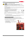
The drawbar of the machine is provided with a pivoting towing eye.
Hook up the machine to the rear hook of the tractor making
sure that the machine is in a stable horizontal position and
that the towing eye is at the same height as the towing device of the tractor.
Turn handle “M” of parking jack to lower or raise the towing
eye until it is correctly aligned with the tractor’s towing device.
Insert the pin in the towing eye and secure it with the safety
pin.
Then disengage the parking device.
Insert the plug of the lighting system for road transport of the machine into the socket of the tractor and check that all the indicator, parking and stop lights are working correctly.
To prepare the bale wrapper for road transport:
Disconnect the hydraulic and electrical feed from the wrapper before road transport.
Make sure that the wrapper is in the correct position for road transport or starting work.
Avoid circulating on the road with heavy rolls of film inserted directly on the pre-tensioners of the film.
Use the film holders on the mudguard for transporting film.
30
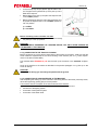
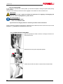
Raise the parking jack “P” using the knob “M”.
Remove the locking pin “S” and turn the parking jack “P”
in the transport position.
Then lock the parking jack “P” using the same pin “S”
again as shown in the picture.
DUETTO 125
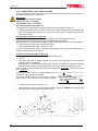
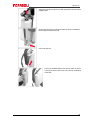
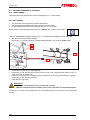
Connect the pick-up lift-up hydraulic pipe to tractor’s outlet. The pipe for the hydraulic lift-up of the pick-up unit is
fitted with a stopcock.
Before lifting up the pick-up unit place the stopcock lever
in the “OPEN” position.
Before transporting along the road, raise the pick-up unit
and place the stopcock lever in the ‘CLOSED’ position to
lock it in position.
1) = “OPEN”
2) = “CLOSED”
Before circulating on the road make sure that:
the tailgate and the guards are closed and locked correctly.
the pick-up is in the “up“ position.
CAUTION!:
BEFORE TOWING, DISENGAGE THE “PARKING DEVICE”, BUT ONLY AFTER HOOKING UP
THE MACHINE TO THE TRACTOR.
5.3.3_CONNECTION TO THE TRACTOR TO WORK
Before connecting any of the various components of the machine to the tractor, make sure that the
tractor meets the requirements for the correct working of the machine (see “2.1.6_Tractor requirements” in the technical data table).
The machines leave FERABOLI S.p.A. with the hook up for the tractor in the ‘standard’ configuration.
Hook up the machine to the tractor as described in the previous paragraph “5.3.2_Hook up to the
tractor for towing”.
CAUTION!:
In any case the towing eye must always be parallel with the ground.
5.3.4_CONNECTION OF VARIOUS DEVICES OF THE MACHINE
After completing the hooking up of the machine to the towing device of the tractor previously shown,
retract the support leg (parking jack) to the rest position.
Then continue with the connection of the various devices of the machine:
Connection of the “Bale Tronic” control unit and of bale wrapper’s control unit.
Connection of the lighting system.
Connection of the hydraulic system.
Connection of the cardan shaft.
31
DUETTO 125
5.3.4.1_CONNECTION OF THE CONTROL SYSTEM
When you connect the machine to the tractor for the first time you must first connect the power supply cable to the battery 12V= of the tractor.
IMPORTANT!:
Be careful not to invert the polarity:
- RED cable = pole “+” (positive)
- BLACK cable = pole “-“ (negative)
This must be done with the tractor off.
The electrical circuit of the machine requires a supply current with negative earth 12V=.
Install the two control units in the cabin of the tractor, using the special attachments that you will
find in the respective accessories of the control units, so that they are clearly visible and within
reach of the operator.
Connecting the “EasyTronic” control unit:
The electrical circuit of the round baler requires a supply current with negative earth 12V=
The plug "S1" of the battery feed cable must be positioned behind the tractor.
Install the terminal in the tractor cabin so that it is clearly visible and within the reach of the operator
Connect the current cable "C1", outside the machine.
Connect the signal cable "CS", in the tractor cabin”.
Check that the terminal has come on by pressing the appropriate key; if the cables have been connected correctly, the system will come on.
Connection of the bale wrapper control unit:
Voltage 12V (battery power with wires of minimum section 4mm ²).
Fuse 16°
The power feed cable is already supplied by the factory with a three-pole circular connector
meeting the ISO 1724 standard.
If the tractor is not provided with this power feed connector it is possible to remove the connector
and use another suitable connector as advised by the centre at which you bought your tractor.
If the connector is removed, please note that the wire marked with 2 is positive while the wire marked
with 1 is negative.
The square connector “A” is for the bale wrapper and must
be fixed in the rear part of the round baler.
The monitor connector “B” is for the control unit, while the
power connector “C” is for the 12V power supply (16 Amp).
32
Connect the power cable “A” to cable “C”.
Check that the control unit of the bale wrapper comes on using key “POWER”. If the cables have
been connected correctly the control unit will light up.
DUETTO 125
5.3.4.2_CONNECTION OF THE LIGHTING SYSTEM
Connect the electric system and check that all the warning, parking and stop lights are working correctly.
Do not insert unsuitable fuses, do not modify the cables and do not replace plugs and sockets that
are not in conformity with the originals.
For any maintenance and/or repair work contact our Assistance Centre.
FERABOLI S.p.A. declines all liability resulting from failure to observe these warnings.
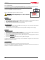
5.3.4.3_CONNECTION OF THE HYDRAULIC SYSTEM
WARNING!:
The hydraulic system is very important and is essential for a correct use.
The hydraulic system must be connected to the tractor by pressure to the hose marked with the
colour red (3).
The required pressure is 150 bar.
The other hose should have (free) return.
The recommended flow is between 25÷30 liters/1’ (a high oil flow will not speed up the system,
but will only generate more heat).
Maximum oil flow is 70 liters/1’.
If the bale wrapper is connected to the tractor, the double acting hydraulic outlet is particularly
necessary to ensure that the pressure in the return line (4) is kept below 5 bar.
It frequently happens that the pressure in the return line increases if the external hydraulic lever
of the tractor is shifted from its engaged position.
The machine is equipped with hydraulic quick-release couplings according to ISO
5675.
Make sure that these couplings are suitable for your tractor.
Pressure peaks increase the risk of damage, especially to the seals of the hydraulic motor.
The hydraulic oil of the tractor must be clean.
Check when the seals and the oil filter of the tractor were last changed.
If the oil of the tractor is too dirty the high pressure filter will block in three minutes.
JD tractors:
If the bale wrapper has to be connected to a tractor with closed centre hydraulic system, close valve
A on the main valve block of the wrapper. Please note that for tractors with open centre hydraulic
system the valve lever should be in position 1, for closed centre systems it should be in position 2.
For tractors with load sensing hydraulic systems (i.e. JD tractor of latest generation which can be
recognized thanks to the lever featuring a rabbit-turtle symbol on the oil outlet) it is enough to limit the
oil flow to the wrapper to ~20 litre/1’ by means of the flow adjuster located on the tractor and leave
valve A in the open position. Do this check and seek advice from the centre at which you bought your
tractor.
33
DUETTO 125
The pipe for the hydraulic lift-up of the pick-up unit is fitted with a stopcock.
Before lifting up the pick-up unit place the stopcock lever
in the “OPEN” position.
Before transporting along the road, raise the pick-up unit
and place the stopcock lever in the ‘CLOSED’ position to
lock it in position.
1) = “OPEN”
2) = “CLOSED”
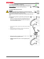
5.3.4.4_CONNECTION OF THE CARDAN SHAFT
The cardan shaft is a CE-certified transmission device.
Each cardan shaft is provided with an operating and maintenance manual; follow and respect all the
information and safety rules for using the cardan shaft contained in this manual scrupulously.
Mount the cardan shaft, provided with the machine, between
the power take-off of the tractor and the transmission box of
the machine; the connection of the cardan shaft on the tractor side is indicated on the cardan shaft itself.
Make sure that the length never exceeds the minimum distance between the machine and the tractor (cambering hazard), while at the greatest distance the two pipes must inserted one into the other by at least 1/3 of their length.
Check that the safety buttons or screws are inserted well into the grooves of the power take-off
and check that the guard rotates freely; if this is not the case apply grease.
Fix the chain to prevent it from self-rotating and self-rotation of the guard.
For further information on the use and maintenance of the cardan shaft read the special instruction booklet provided with it.
CAUTION!:
After all maintenance work on the cardan shaft replace the protective covers on the cardan shaft.
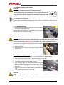
5.3.4.5_MOUNTING THE BALE DROP MAT
The bale drop mat “T” must be mounted at the rear tube using the special screws supplied, according to the figure given below. The mat must be placed on the tube.
34
DUETTO 125
5.4_WORK TESTS
CAUTION!:
The machine must always be attached to the tractor before any operation, whether empty or
containing a bale.
After making the various connections described above:
Round baler:
Start up the tractor without engaging the PTO and check that the various functional movements
of the round baler are working correctly.
Check that the hydraulic system is working correctly:
Open/Close the tailgate.
Lower/Raise the pick-up unit.
Activate/Deactivate the knives.
Check the electrical connection to the “Bale Tronic” control unit:
Turn the control unit on with the switch in position 1 and wait for the data to load.
Check the operation of the electric system:
Direction indicators.
Parking and stop lights.
Check the operation of transmission:
Engage the PTO.
CAUTION!:
Before engaging the PTO, make sure that there are no persons in the vicinity.
Operate carefully the first time making sure that all the mechanical parts and transmission are working correctly.
Bale wrapper:
It is always advisable to do a trial run to check that all the components are working as they should.
To do a trial run, connect the machine to the tractor which is to be used in the field.
Before doing the trial run:
Make sure that there are no persons in the danger zone.
Make sure that the hydraulic system of the tractor is connected correctly and that the hydraulic
connections between the wrapper and the tractor are in the correct positions.
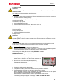
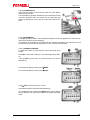
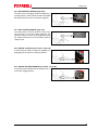
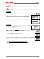
When turning on the display will show the wording: FERABOLI ver.xxxx
It will then go into standby mode, displaying the text:
WRAPPER CYCLE 0-20 _
BALES: 1 xxx
Start up the tractor, adjust the engine speed of the tractor to the
speed which will be used in the field (normally 540 rpm); connect the hydraulic system.
Do a trial run with the film cutting devices (switch 1).
The film cutting devices must move freely in both directions.
Close the film cutting devices.
Lower the load arm (switch 3).
Position the platform (switch 4) horizontally.
The platform indicator (= the line after the wrap number) must also be horizontal.
Press the switch 2 of the wrap arm and keep it held down for 5÷10 turns.
During this period of time the control unit will learn the correlation between the wrap arm speed
and the modulation of the feed voltage to the proportional valve.
When the switch is released the wrap arm stops perpendicularly to the structure.
Use the switch 4 of the platform to incline it forwards.
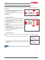
The following message will appear on the display: “READY TO LOAD THE BALE”.
35
DUETTO 125
5.5_SETTING THE MACHINE TO WORK
Before starting work make all the necessary adjustments to prepare the machine for your specific
work requirements.
Connect the machine to the tractor as described in the previous chapters.
CAUTION!:
- Loading and threading the twine for tying must be carried out while engine and control unit are off.
- Pay great attention to the twine cut knife whenever you work next to it.
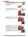
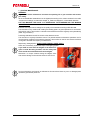
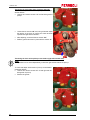
5.5.1_TWINE LOADING
For the twine binder to work well we advise using propylene twine with a yarn count from 500 to 750
or 1000 m/kg.
The twine binder of your round baler can also work with other types of twine.
Open the right side guard and place the rolls of twine in the special boxes.
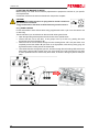
Connect the rolls, one to the other, in two groups of two (1+2 and 3+4), passing the twine
through the slots of the separators “S”.
Pass the ends of the two twines through the twine braking device “F1” and pass them once
completely around the wheels “R” (as shown in the figure)which, while turning during tying, will
signal that the twine is being wound around the bale.
36
Then thread the twine through the eyes “O”, and then through the two bushings “B” and the two
twine braking devices “F2” located on the arm of the binder; then pass it through the two pipes
so that it protrudes from the other end by about 20cm, as shown in the figure (use one twine per
path).
DUETTO 125
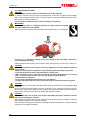
5.5.2_NET LOADING
The machine can use rolls from 2000 to 3000 metres.
The hole inside the cardboard tube of the roll of net must be 75-78mm.
For good performance of the tying unit we advise using a net of 14˜16 (g/m).
WARNING!
Switch on the “F_bus” system and follow the instructions for loading the net shown in paragraph “10.8.2_Net loading”.
IMPORTANT!
Take great care to push the net roll onto the tube correctly so that it rotates in the right direction as shown on the decal
After positioning the net and before commencing work, bring the net wrapper to its original
position.
Make sure that the cutter has finished its movement (net wrapper in the original position at
the end of its stroke)
CAUTION!
Beware of the blade of the net wrapper when doing any work in its vicinity
IMPORTANT!
Pass the net over the rollers following the path
shown by the decal located on the machine.
37
DUETTO 125
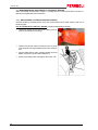
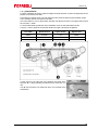
5.5.3_ADJUSTING THE PICK-UP WHEELS
To adjust the working height of the pick-up:
To raise or lower the height of the pick-up change the position of the pin “S”, located on the arm of the support wheels,
by inserting it into one of the holes located on the support
structure, depending on work needs.
To raise or lower the pick-up:
Use the lever of the tractor selector remembering to open the
stopcock located near the quick release fitting (position: 1 =
OPEN).
WARNING!:
- The tines of the pick-up must never touch the ground; therefore adjust the working height of
the pick-up so that the tines remain at least 2÷3cm above the ground.
- Insert the pin “S” in the same position on both left and right sides of the pick-up.
38
DUETTO 125
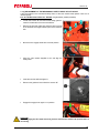
5.5.4_FEED PLATE
In machines fitted with cutting system, the feed plate optimises the collection and channelling of the product.
The distance of the plate from the tines of the pick-up can be
adjusted by moving the blocks “T”.
With the machine still and the tractor engine off:
Remove the plate.
Loosen the screw “V” that secures the block “T”, and
position it in one of the holes located on the side of the
pick-up to suit the work to be done.
Then screw back the screws “V”.
WARNING!:
- Position the block “T” in the same position on both the left and right sides of the pick-up.
Remount the plate.
For short products and/or swathes of low volume the plate should be close to the pick-up tines while
for tall products and/or voluminous swathes the plate should be further from the tines of the pick-up.
5.5.5_CHOOSING WORKING PRESSURE
The operating pressure must be selected that suits the density required and on the basis of the product to be baled.
The pressure selectors are located in the rear part of the machine on both sides.
To change the working pressure:
Unscrew and rotate the two small doors located on the
rear guards.
To change the working pressure turn selector “M” to the
number selected for the density desired:
position “1” = low density
position “7“= high density
Make sure to position both switches to the same number.
39
DUETTO 125
5.5.6_CUTTING SYSTEM
If your machine is provided with a cutter system, you will have the option of cutting the product while picking
up the swathes.
Using the control terminal, the knives must be engaged in the chamber in order to be able to cut.
IMPORTANT!
Switch on the “F_bus” system and follow the instructions for engaging or disengaging the
knives as shown in paragraph 8.8.3_Cutter device”.
The cutting length is :
77mm for TOPCUT model
45mm for ULTRACUT model
If you wish to cut a longer product it is necessary to remove some of the knives.
Further information regarding the adjustment, replacement and maintenance of the knives can be found in the
paragraph “7.7_Maintenance and adjustment of the cutter”.
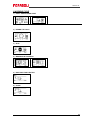
5.5.7_LOADING THE PRE-TENSIONERS
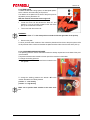
Open the pre-tensioner head as shown in the figure and secure it
firmly with the hook.
Release the knob and push the spindle upwards.
Position the roll of film so that it is unwound from the internal side.
40
DUETTO 125
Release the handle and press the shaft downwards until the handle
engages again.
Support the head of the pre-tensioner while the hook is unfastened.
Do not forget to release the hook!
Pull out the film end.
The film is threaded between the tension rollers as shown
in the figure above and the free end of the film is attached
to the bale.
41
DUETTO 125
5.6_IN-FILED OPERATION
Maximum performance when the various products are harvested and baled can be only ensured if
the following instructions are complied with.
Conditioning:
It is important that forage is conditioned as this ensures an even moisture content of stems and
leaves.
Long stem crops, which are difficult to work with, elastic and tough, must be conditioned in order to
break the stems and reduce their resistance to rolling when the bale is being formed.
To bale maize stalks it is advisable to shred for better bale formation and density.
Do not shred too fine!
Swathes:
The preparation of the swathes (windrow) is very important to
ensure bales are correctly formed.
When the forage has been cut and properly dried the
swathes must be formed.
The swathes can be single or double but not greater than the
capacity of the pick-up.
When double swathes are made it is important that they be
left beside each other and not piled into one heap.
Individual swathes can be 0.50-0.60 m wide, but in this case
a ‘zig-zag’ pattern should be followed so that the machine
can be fed correctly.
42
DUETTO 125
6_OPERATION
6.1_ SWITCHING ON
When the machine has been set up as previously described, you can now start working
Switch on the “F_bus” control system in order to start work.
Before starting work you can use the terminal to review and/or change the program values with
which your machine has been set up.
Before starting work:
make sure that the arms of the tying units (twine binder and net wrapper) are in the rest position and that
the respective cutting devices are released (deactivated).
check that the tailgate is closed correctly.
make sure that the bale wrapper is in the correct position and that the rotating platform is in the horizontal
position.
Take a position on the swathe: open the pick-up stopcock (position “1 = OPEN”)
and lower it.
You can now engage the PTO and begin collection. The rotation speed of the PTO must be between 450 and
540 rpm, and this range of values must not be exceeded.
For further information on how to change the programming of the “F_bus” control system and how to engage
and disengage the knives, see chapters “8.3_EasyTronic”.
6.2_ FEED SPEED AND LOADING
The feed speed depends on the type of product to be baled and the ground contours.
Proceed with the tractor in motion so as to load the product into the machine’s chamber correctly.
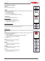
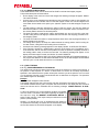
6.3_BALE TYING, WRAPPING AND UNLOADING
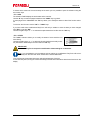
When the bale is completed the control unit warns you with a
“STOP” message on the display and a continuous acoustic signal
to stop the tractor immediately so that the tying device can tie the
bale just finished.
Once tying is complete and after the word “END” appears on the
display, the sensor on the shaft of the net roller will automatically
start to transfer the bale towards the bale wrapper as soon as net
has wrapped the bale.
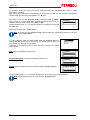
Before starting to wrap a bale check that the wording “READY TO LOAD THE BALE” appears on
the last line on the display.
Do not touch the monitor of the bale wrapper before the bale
has been wrapped and is ready for offloading.
CAUTION!:
Do not touch the monitor of the bale wrapper for the following reasons:
The bale wrapper controller automatically closes the tailgate of the round baler as soon as the bale has been
loaded.
The bale wrapper controller constantly checks that the
wrapping is proceeding correctly.
43
DUETTO 125
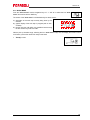
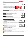
When the bale has been completely wrapped the wording “READY TO OFFLOAD” appears on the
display.
It is now possible to offload the bale with the “AUTO START” switch”.
CAUTION!:
Before offloading the bale from the footboard of the wrapper:
- Make sure the ground is level or that the machine is in a suitable position if the
ground slopes.
- Move any persons near the machine, especially behind the bale wrapper, to a
safe distance.
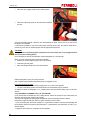
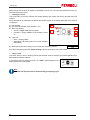
If the power has been interrupted for any reason by the lasting
wrapping, it is advisable to start the wrap arm by pressing the
switch 2 downward and holding it down for about 4÷8 turns.
During this period the computer will calibrate the proportional valve.
Since the wrapper works completely automatically, as described in
point “8.3_Bale Wrapper Control Unit”, the driver must simply provide a good quality of the bale for the wrapper and the bale wrapper
control system will do the rest.
Some valuable advice is given below:
It is necessary for the net to be wrapped around the bale before the bale is ejected from the
round baler.
Do a visual check (the net can be seen between the front rollers of the round baler).
If during the setting of the sequence, the question “WAIT FOR START SIGNAL BEFORE
TURNING OVER” was answered with NO, the bale will be offloaded automatically as soon as
the film is cut.
Use this option only on flat ground and where hazards cannot be caused!
CAUTION!:
If it is necessary to leave the tractor cabin for any reason, for example to
replace the film, stop the tractor engine and remove the key from the
dashboard!
CAUTION!:
Never forget to turn on the safety switch!
This bale wrapper is an automatic machine with very strong cutting
elements that are very dangerous and therefore any accidental or
sudden movement could be very dangerous!
Clean the area of the load arm regularly of grass residue (for example when the film is replaced), especially the flaps of the bale sensor.
6.3.1_LOADING THROUGH THE BALE WRAPPER WITHOUT FILM ON THE BALE
If the number of wraps is set to 0, the bales are simply loaded through the bale wrapper without applying any film to the bales.
The bale wrapper may then be used to group the bales for easier collection.
6.3.2_INTERRUPTED CYCLES
An interrupted cycle can be resumed at any time. The system memorises the last phase of a cycle
sequence even when the cycle is the result of a series of manual or automatic operations.
44
DUETTO 125
If the bale should catch fire:
Immediately expel the bale and keep the tailgate open.
Raise the unloading platform of the bale wrapper completely.
Move the tractor and machine away from the product still to be collected and
any other inflammable material.
Put the fire out using the extinguisher, advised as part of your equipment or
using water.
6.4_UNBLOCKING THE PRODUCT
CAUTION!:
Should the round baler jam, do not try to remove the product from the machine while it is
working.
6.4.1_CLEARING THE PICK UP
The product is blocked between the feed plate and the tines of the pick-up.
CAUTION!:
Before attempting to clear away the product:
- Switch off the tractor, remove the keys from the dashboard and wait for
all the moving parts of the machine to stop completely.
- Disconnect all the electronic functions and cut off the current to the control
units.
Unhook and remove the safety pin “S” (on both the left
and the right sides) and raise the lock hook “G”.
Remove the feed plate.
Put on the cut resistant gloves and with the help of suitable equipment clear the area where the product has
blocked up.
When you have completely cleared the area of the blockage
remount the feed plate and secure it again with the hook “G”
and the pin “S”.
After completing the operations described above re-engage the PTO.
If the pick-up fails to turn the transmission safety bolt of the pick-up could have sheared.
To replace it refer to paragraph “7.2.1_ Replacement of the pick-up safety device”.
6.4.2_UNJAMMING THE CUT UNIT
An excessive volume of product has blocked between the rotor and the bottom feed plate.
CAUTION!:
Before attempting to clear away the product:
- Switch off the tractor, remove the keys from the dashboard and wait for
all the moving parts of the machine to stop completely.
- Disconnect all the electronic functions and cut off the current to the control
units.
Open the right side guard and pull out the unblocking handle from its seat.
45
DUETTO 125
Move the rotor engage handle to the neutral position.
Insert the unblocking handle on the shaft of the transmission box.
Using the unblocking handle, rotate the rotor anticlockwise for about 1/2÷3/4 of a turn to free it from
the product accumulated.
If it should be necessary to remove a foreign body manually (stone, stick, etc.) before doing this remember to put on the cut resistant gloves and use appropriate equipment.
CAUTION!:
Take great care in performing these operations as the area of the rotor is very dangerous due
to the presence of cutting knives.
If it is necessary to remove the feed plate, read the paragraph “5.5.4 Feed plate”.
When you have cleared the area concerned completely:
Remove the crank handle and put it back in its housing.
Close the right side guard.
Move the engage handle back to the drive position.
Refit the feed plate if it was previously removed.
After completing the operations described above re-engage the PTO.
If the rotor should fail to rotate:
Make sure that you have moved the engage lever “L” to the correct position.
The bolt of the safety system of the mechanical CUT transmission may be sheared.
To replace it consult the paragraph “7.2.2_ Replacement of the mechanical safety device of the CUT
device.”
6.4.3_AUTOMATIC CLEARING “AFC” OF THE CUTTER
If your round baler is provided with “AFC” safety devices, reduce the number of rpm of the tractor to a
minimum and wait for the product to be cleared.
This device is engaged and disengaged automatically until the blockage has been cleared.
If the tractor engine should stall, start it up again and keep it at a minimum.
- If you are working with the knives inserted, it is a good idea to stop the machine and disengage the
knives before clearing the product (see paragraph “7.7_Maintenance and adjustment of cutter”); proceed as follows.
- Engage the knives again on completion of this operation.
46
DUETTO 125
CAUTION!:
During this entire operation do not approach or allow anyone else to approach the machine.
The “AFC” device could clear the blockage at any moment and the rotor could resume its
normal rotation.
6.4.4_MACHINE STOP
IMPORTANT!:
At the end of the work the operator shall:
- Stop the machine.
- Make sure that all the moving parts of the machine have stopped and are in the rest position.
- Switch off the tractor and remove the keys from the dashboard.
- Disconnect all the electronic functions and cut off the current to the control units.
6.4.5_PARKING
CAUTION!:
Before taking the machine back to its storage area make sure that there is no bale still loaded.
At the end of work deposit the machine in a suitable flat area to avoid sudden accidental movements.
Apply the mechanical or hydraulic parking device (only for machines provided with this mechanism ) see “3.4.11_Parking device”.
Lower the parking jack to the ground and block it with the safety pin. Raise the machine by
2÷3cm from its connection to the tractor in order to unhook it.
Raise the cardan shaft support, then disconnect the cardan shaft from the tractor and rest it on
the support. Secure it with the chain.
De-pressurise hydraulic circuit and:
Rest the small wheels of the pick-up on the ground; move the lever of the cock (valve) to the
“CLOSED” position; then disconnect the tube.
Then disconnect all the other tubes from the hydraulic system.
Disconnect the electricity cables and the cables of the lighting system and wrap them around the
cable support.
Disconnect the signal cable of the “Bale Tronic” and of the wrapper control unit and wrap them
around the cable support; then remove the control units and place them in a safe place protected
from dust and weather conditions.
Remove the safety pin and the locking pin from the towing eye
of the drawbar and then unhook the tractor from the machine.
Remove the tractor from the vicinity of the round baler.
47
DUETTO 125
7_MAINTENANCE, LUBRICATION AND CLEANING
The personal in charge of servicing, lubricating and cleaning the machine must have read the safety
prescriptions provided in this manual.
CAUTION!:
Any maintenance, lubrication and cleaning operation must be carried out following the instructions given below:
- Stop the machine and disengage the PTO.
- Lay the machine on the ground in a stable position.
- Turn off the tractor engine and remove the keys from the dashboard.
- Engage the hand brake.
- Always cut off the current to the control unit.
- Read the operating manual.
- Wear suitable personal protective equipment (PPE).
- Never raise the machine from the ground.
WARNING!:
Do not dump oil, grease or old equipment. Contact specialist authorized firms.
CAUTION!:
Read the section on safety precautions carefully, particularly:
Definitions of OPERATOR OR MACHINE OPERATOR
Duties of the MECHANICAL MAINTENANCE TECHNICIAN
Accident prevention signs and the precautionary measures to be adopted.
PERSONAL PROTECTIVE EQUIPMENT to be used.
CAUTION!:
The hydraulic system is under heavy pressure.
Connect properly cleaned hydraulic couplings and make sure the hydraulic circuit of tractor and
machine are pressure-free.
To prevent hydraulic couplings from getting dirty or damaged always fit - after use - the original
plastic protection caps supplied.
Check and, if necessary, replace damaged hoses and unions. As a general rule, every hose must
be replaced after 5 years from the date printed on the hose.
High-pressure hydraulic oil can penetrate your skin and cause serious injuries, hence we recommend that you always release pressure before disconnecting hoses and carrying out any controls.
Before pressurizing the system again check that hoses and connections are tight. We advise you
to use a sheet of blotting paper or cardboard to detect leaks (if any).
If hydraulic oil under pressure penetrates your skin immediately apply to a first-aid medical
centre or hospital otherwise the risk of serious infections could be run.
CAUTION!:
- It is strictly forbidden to service, lubricate or clean the machine if machine parts are moving.
- Only use suitable equipment for maintenance operations.
- Observe the maintenance times and methods given in this manual.
- If necessary, refer to the diagrams enclosed with this manual: electrical, hydraulic.
If necessary, contact FERABOLI S.p.A.’s after-sales service centre.
48
DUETTO 125
7.1_ROUTINE MAINTENANCE
WARNING!:
Regular and careful maintenance increases the operating life of your machine and ensures
your safety.
All the screwed/bolted assemblies must be tightened according to the values contained in the table
“torque wrench settings” enclosed with chapter “9_Tables and diagrams”, unless stated otherwise.
FOR THIS MACHINE THE VALUE “8.8” REPRESENTS THE STANDARD AND THE MINIMUM
QUANTITY USED
Diameter and torque wrench settings for the quality of the materials according to DIN ISO 898.
The lubrication of any machine with rotating and rubbing parts is of great importance for the duration
and working order of the machine. Lubrication should therefore be done regularly and systematically
(table “9.2_Lubrication”).
Prearrange maintenance work for which the due dates are known.
This manual is of a purely informative nature. The periods between maintenance operations are for
normal working conditions of the machine therefore if the machine is used in more severe conditions
it is logical to increase the frequency of maintenance.
Replace any damaged parts: ALWAYS USE ORIGINAL SPARE PARTS.
Check and, if necessary, replace the lamps of the lighting system.
If you need to work while the tailgate of the machine is
open or inside the baling chamber, lock the safety cock
which avoids the accidental descent of the tailgate.
Remember to re-open it before closing the tailgate, otherwise serious damage to the machine structure could occur!
Do the maintenance work exactly as indicated in this manual and have any worn or damaged parts
replaced by specialised personnel.
49
DUETTO 125
7.2_ MAINTENANCE AND ADJUSTMENT OF THE SAFETY DEVICES
Some of the safety devices listed in chapter “3.4_Safety devices” of this manual need to be reset, refitted and/or adjusted after their intervention.
7.2.1_ REPLACEMENT OF THE PICK-UP SAFETY DEVICE
If the bolt located on the safety device of the pick-up should shear off or break, replace it with one of
identical quality:
bolt “B” TE M8x 45-10.9 UNI 5738 – DIN 960 (not galvanised partially threaded).
50
Loosen the screws “V” and pull out the safety guard located on the left side of the pick-up.
Remove the bolt and make sure that there are no pieces
of the sheared bolt caught between parts of the transmission.
Align the safety device holes, manually rotating the screw
feeder, reinsert the new bolt “B” and tighten it.
Remount the safety guard and retighten the screws “V”.
DUETTO 125
7.2.2_REPLACEMENT OF THE MECHANICAL SAFETY DEVICE OF CUT DEVICE
If the bolt located on the mechanical safety device of the rotor should break replace it with one of
identical quality:
bolt “B” TE M14x 60-8.8 UNI 5738 – DIN 960 (not galvanised; partially threaded).
Loosen the screws “V” and remove the safety guard located on the left side of the rotor transmission.
Remove the bolt and make sure that there are no pieces
of the sheared bolt caught between parts of the transmission.
Move the rotor engage handle to the neutral position.
Using the crank handle supplied to turn and align the
safety holes.
Insert the new bolt “B” and tighten it.
Remount the guard and screw back the screws “V”.
Engage the engage lever again in run position.
CAUTION!:
Before engaging the PTO make sure that you have removed the handle and repositioned it in
its housing.
51
DUETTO 125
7.3_ ADJUSTING CHAIN TENSION
Regularly check the tension of the transmission chains and
the working of the automatic tensioners where provided.
The value “F” of chain stretching must be 5-10 mm.
7.3.1_ ADJUSTING THE AUTOMATIC PRE-TENSIONERS
The roller chains of the machine are stretched automatically by spring tensioners.
Regularly check the correct tension of the chains and readjust the tension whenever necessary.
To check and adjust the tension of the chains, open the front
left side guard:
Using a spanner n. 13, turn the screw of the safety lock
“S” anticlockwise so as to unlock.
Unhook the rubber hook “G” to open the front left side
guard.
After making the adjustment close the guard, making the
safety lock “S” click into position.
Secure it again with the hook “G”.
To check and adjust the chain tension of the tailgate rollers,
proceed as follows:
Loosen the screws “V1” off without removing them.
Pull the right lower guard out of the tailgate.
Once the adjustment has been completed, refit the guard
and screw it in place with the screws “V1”.
To adjust the automatic tensioners proceed as follows:
Loosen off nut “D1” act on nut “D2”, adjust distance “X”
that must be about 10÷15mm.
52
After adjusting, tighten nut “D1”.
DUETTO 125
7.3.2_ADJUSTING MANUAL TENSIONERS
The roller chains of the machine are stretched by means of tensioners whose adjustment must be
done manually.
Regularly check the correct tension in the chains and adjust it whenever necessary.
To check and adjust drive chain tension, proceed as follows:
Open left front side guard (as previously described).
Loosen the two screws “V” and move the tensioner as
needed so as to tension the chain.
After adjusting, screw back the two screws “V” again.
Close the guard at the end of the adjustment.
Tensioning the chain of the collection unit:
Loosen screws “V” and remove the guard.
Loosen the three screws “V3” and, using a hammer adjust the tension of the chain by moving the chain tension
downwards with light hammer strokes.
After adjusting, screw back the three screws “V3” again.
Refit the guard and screw it in place with the screws “V”.
Tensioning the rotor chain:
To check and adjust chain tension of rotor, open the right
front side guard:
Loosen the four screws “V” and remove the guard.
From inside the side of the machine, loosen the two
screws “V2”.
Loosen the lock nut “D” and screw in or out the adjustment screw “VR” to obtain the correct tension in the
chain.
Having made this adjustment, tighten the lock nut “D”
again and from inside the side of the machine tighten the
two screws “V2” again.
Refit the guard and screw it in place with the screws “V”.
Shut the right front side guard.
53
DUETTO 125
Tensioning the reel-holder chain of pick-up (left side):
To check and adjust chain tension of pick-up reel-holder proceed as follows:
Unscrew and remove screws “V” and left side guard of
pick-up.
Loosen the two screws “V2” and, using a hammer adjust
the tension of the chain by moving the chain tensioner
upwards with light hammer strokes.
After adjusting, screw back the two screws “V2”.
Refit the guard and screw it in place with the screws “V”.
Tensioning the chain of the pick-up screw feeders (right side and left side):
NOTE:
This operation is to be done independently on both the right and left sides of the pick-up.
To check and adjust chain tension of pick-up screw feeders
proceed as follows:
Unscrew and remove screws “V” of both right and left
side guards of pick-up.
54
Remove the guards.
DUETTO 125
Right side:
Loosen the two screws “V2” and, using a hammer adjust
the tension of the chain by moving the chain tensioner
with light hammer strokes.
After adjusting, screw back the two screws “V2”again.
Refit the guard and screw it in place with the screws “V”.
Left side:
Loosen the two screws “V2” and, using a hammer adjust
the tension of the chain by moving the chain tensioner
with light hammer strokes.
After adjusting, screw back the two screws “V2”again.
Refit the guard and screw it in place with the screws “V”.
Tensioning the wrapper chain:
There are two drive chains that must be tensioned in the following way:
1) Platform main drive chain, n°.”7”.
To tension this chain, loosen off screws “4” and press the tension block firmly against the
chain.
Re-tension the bolts “4”.
2) Secondary drive chain n°.“6”.
To tension this chain loosen bolt “3” and adjust the tension screw “8”.
Tighten bolt “3”.
55
DUETTO 125
7.4_ADJUSTING THE TYING UNITS
7.4.1_DOUBLE TWINE BINDER
CAUTION!:
Before doing any maintenance or making any adjustments to the double
twine binder:
- Switch off the tractor engine, remove the keys from the dashboard and
wait for all the moving parts of the machine to stop.
- Disconnect all the electronic functions and cut off the current to the control units.
Basic Control allows you to control the parameters with which to set
the double twine tying, independently of the value of the bale diameter:
“A” = distance of the twine from the head of the bale.
“B” = number of turns of twine around the head.
“C” = number of turns of twine around the centre.
To modify the values consult the paragraph “8_Programming the
EasyTronic control unit”.
Adjusting the twine braking device:
There are some twine braking devices on the round baler (located
on the twine roll box) to adjust the tension of the twine.
Adjust the tension of the twine on the bale by turning the nuts “D”
and screws “V” of the twine braking devices, to compress or release the springs “M”:
Tightening the spring “M”, the twine will be more taut.
Loosening the spring “M”, the twine will be slacker.
CAUTION!:
Take great care when working near the twine braking devices
located on the arm of the binder, and the blade of the binder.
Replacing the blade:
If the blade of the double twine binder does not cut the twine any
more, you can:
replace it (if broken);
turn it round (if worn).
Unscrew the two screws “V” and replace it with one that is the
same or turn it round; screw it back in place with the two screws
“V”.
WARNING!:
Take great care around the blade of the binder.
NOTE:
If necessary adjust stroke of the blade arm using fork “F”.
56
DUETTO 125
7.4.2_NET WRAPPER
CAUTION!:
Before doing any maintenance or making any adjustments on the net
wrapper:
- Switch off the tractor engine, remove the keys from the dashboard and
wait for all the moving parts of the machine to stop.
- Disconnect all the electronic functions and cut off the current to the control
units.
EasyTronic gives you the possibility of setting the number of turns for wrapping the bale.
To change this value consult paragraph “8_Programming the EasyTronic control unit”.
Adjusting net feed arm:
Depending on the type of lock mounted on the right side of the machine, adjust the travel of the net
arm against the intermediate roller, adjusting the lock itself.
CAUTION!:
Take great care working near the net wrap arm and the blades of the tying device.
A) Internal lock on the right side:
Open the right front guard.
Loosen the 2 screws “V” and adjust by moving the block “T”
forwards or backwards.
NOTE:
If you move the block “T” too close to the roller, the arm could
move forward far enough to collide with the roller during wrapping.
If, on the other hand, the block “T” is too far from the roller the
movement of the arm could be insufficient and the net will not be
taken and the bale not wrapped.
When the adjustment has been made screw back the 2 screws
“V” and close the guard.
B) External lock on the right side:
Open right front guard.
Loosen the nut “D” and screw in or out the adjustment screw
“VR” to obtain the right distance of the net arm from the intermediate roller.
NOTE:
If the screw “VR” is tightened too much the arm could collide with
the roller itself during wrapping.
If instead the screw “VR” is too loose the arm could move too little
and then the net would not be taken and the bale not wrapped.
After making this adjustment tighten the nut “D” and close the
guard.
Replacing the blade:
If the wrapper blade sections do not cut the net (the blades are
worn or broken) they must be replaced.
Remove the rivets that originally fixed the blades.
Replace the worn or broken blades and secure them again to
the wrapper arm using M6X20 screws (instead of rivets).
CAUTION!:
Take great care regarding the blade sections.
57
DUETTO 125
7.5_ELECTRICAL AND ELECTRONIC COMPONENTS
Check that the cables of the electrical system and the control unit have not been crushed or
damaged.
Check that all the sockets, plugs, cables and sensors are always cleaned of any deposits of earth
or product.
Check and if necessary replace broken bulbs in the lighting system.
Further information regarding the maintenance of the control units can be found in the Chapter
“8.1_EasyTronic”
WARNING!:
After the first 200 bales produced check the machine in regard to the points described above.
7.5.1_SENSORS
A series of “Proximity Switches” (sensors) have been
placed on the machine. These regulate and monitor the various working phases of the machine through the control units.
Adjust the distance “X” between the sensor “S” and its
magnet “C”, as shown in the figure (the example is only indicative).
“X” = must send the signal to the control unit
With the “EasyTronic” control unit on, adjust the nuts that
secure the sensor “S” to its support to move it closer to
or further from the respective magnet “C”.
Then secure the nuts and check the signal again in the
control unit for the sensor “S”, which might have been
moved by the action of tightening the nuts.
WARNING!:
Adjust the sensors so that they never touch or collide with their corresponding magnets when working.
CAUTION!:
Make all the adjustments on all the sensors located on the machine observing the safety regulations and taking great care at the points where there could be particular danger.
If it should be necessary, in order to gain access to the sensors, to open or remove the guards,
remember always to close them and reposition them after finishing the adjustments.
7.6_ADJUSTING THE PICK-UP
7.6.1_ADJUSTING THE WORKING HEIGHT OF THE PICK-UP
The working height of the pick-up is adjusted by moving the small wheels to one of the predetermined
positions in the same way on each side of the pick-up.
WARNING!:
The pick-up tines must never touch the ground; therefore adjust the working height of the
pick-up so that the pick-up tines remain above the ground by a minimum of 2÷3 cm.
For further information consult the paragraph “5.5.3_ Adjusting the pick-up wheels”.
58
DUETTO 125
7.6.2_ HYDRAULIC RAISING OF THE PICK-UP
You can raise and lower the pick-up easily using two lateral hydraulic cylinders by engaging the lever of the hydraulic distributor on the tractor, first
opening the stop cock (cock lever in the “OPEN” position”).
7.6.3_ REPLACING THE PICK-UP TINES
CAUTION!:
Before replacing and/or doing maintenance on the tines of the pick-up:
- Switch off the tractor engine, remove the keys from the dashboard and
wait for all the moving parts of the machine to stop.
- Disconnect all the electronic functions and cut off the current to the control
units.
If the pick-up tines mounted on the reel-holder of the pick-up have
to be replaced:
Loosen the 4 screws “V” (2 above and 2 below) which fix the
band “F” at the level of the tine to be replaced and then pull
out the band, passing the head of the screws “V” through the
hole of the slot located on the band.
Unscrew the bolt “B”, remove the tine “D” and the related
block “T”.
Replace the pick-up tine “D” with a new one of the same type.
Screw back the block “T” and the bolt “B”.
Remount the band “F” inserting it over the screws “V” and
then push it all the way against the screw.
Finally screw back the 4 screws “V” with a tightening value
of 15Nm.
59
DUETTO 125
7.6.4_ ADJUSTING THE PICK-UP CAM
CAUTION!:
Before adjusting and/or doing maintenance on the pick-up cam:
- Switch off the tractor engine, remove the keys from the dashboard and
wait for all the moving parts of the machine to stop.
- Disconnect all the electronic functions and cut off the current to the control
units.
Adjust the position where the product is released by the pick-up tine by moving the cam located on
the right side of the pick-up.
Unscrew and remove the screws “V” and the right guard of the
pick-up.
Loosen the 4 screws that hold the cam.
Adjust the position of the cam, rotating it so as to move the pick-up
tine nearer or further from the transport assembly.
Rotate the cam towards the position:
“A” = to move the tine nearer to the pick-up assembly.
“B” = to move the tine away from the pick-up assembly.
Screw back the 4 screws to secure the cam again.
Refit the right guard and secure it with the screws “V1”.
7.7_MAINTENANCE AND ADJUSTMENT OF THE CUT DEVICE
The knives or false knives must be removed or put back whenever you do the following:
Remove all or only some of the knives.
Remove some of the knives for sharpening.
Replace all or only some of the knives with false knives.
CAUTION!:
Before removing or assembling knives:
- Open the tailgate and lock it in position using the Tailgate safety lock device, following the instructions given in the paragraph “3.4.12_ Tailgate safety lock”.
- Before closing the tailgate remember to release its safety lock.
- Switch off the tractor engine, remove the keys from the dashboard and
wait for all the moving parts of the machine to stop.
- Disconnect all the electronic functions and cut off the current to the control
units.
CAUTION!:
The knives are sharp and cut easily, it is advisable to use cut resistant gloves!
60
DUETTO 125
7.7.1_REMOVAL OF KNIVES
To remove the knives they must be disengaged, doing this directly from the terminal of the “F_bus” system.
In this regard consult paragraph “8.8.3_Cutter device”.
a) Move the rotor engagement lever "L" to the neutral position.
b) Release the knives by moving the handle “M” located on the right side of the machine, to position “knives
off” (lever “M” lowered).
(a)
(b)
L
M
lever “M” lowered position “KNIVES OFF”
Enter the bale formation chamber and take hold of the knives to be removed at the tip then lift and pull
them out.
To extract them more easily you can rotate the rotor manually proceeding with caution.
IMPORTANT!
It is necessary to put false knives in the place of the knives removed so that the product does block up the seats of the
knives and make it difficult to replace the knives later.
c) When you have finished this operation, anchor the knives again moving the handle “M” to position
“knives on” (lever “M” raised).
d) Shift the engagement lever "L" back to the drive position.
(c)
(d)
M
L
lever “M” raised position “KNIVES ON”
61
DUETTO 125
7.7.2_FITTING KNIVES OR FALSE KNIVES
To mount the knives or the false knives, the knives must be disengaged doing this directly from the terminal
of the “F_bus” system.
In this regard consult paragraph “8.8.3_Cutter device”.
a) Move the rotor engagement lever "L" to the neutral position.
b) Release the knives by moving the handle “M” located on the right side of the machine, to position “knives
off” (lever “M” lowered).
(a)
(b)
L
M
lever “M” lowered position “KNIVES OFF”
Enter the bale formation chamber and insert the knives or false knives in the slots.
To make this easier you can rotate the rotor manually proceeding with caution.
Make sure that they are correctly inserted on the pin.
IMPORTANT!
If the knives or false knives are not correctly anchored there is the danger that they will enter
the bale formation chamber together with the product to be baled.
Knives engaged correctly
False knives engaged correctly
c) When you have finished this operation, anchor the knives again moving the handle “M” to position
“knives on” (lever “M” raised).
d) Shift the engagement lever "L" back to the drive position.
(c)
(d)
L
lever “M” raised position “KNIVES ON”
62
DUETTO 125
7.7.3_SHARPENING OF THE KNIVES
The knives should be sharpened with suitable equipment whenever necessary. Bear in mind that
knives sharpened well reduce the power requirement and give a better quality cut.
WARNING!:
- When sharpening, be careful not to cause the knives to heat
up as this can compromise their resistance to wear.
- Only the part marked as “SIDE” of the knife should be sharpened.
CAUTION!:
- Always work with care bearing in mind the safety regulations.
- The knives are sharp and cut easily; handle them with great care.
- Always use adequate gloves and/or protective gear.
7.8_WHEELS AND TYRES
Tyres of various dimensions can be fitted on the machine. Check the inflation pressure regularly for
the type of tyre fitted to you machine referring to the pressure values given in the table “9.5_Pressure
value of tyres”.
The inflation pressure of the pick-up wheels should be: 2,5bar.
Check the torque of the nuts on the stud bolts of the wheel hub regularly. It should be 250Nm.
Repairs to the wheels and tyres must be done by specialised personnel provided with
suitable equipment.
7.9_BOLT TIGHTENING
Regularly check the securing bolts and screws and if necessary adjust them to the torque values advised in the table “9.4_Torque wrench setting”.
Check if all the bolts are correctly tightened after the first three hours of work.
Check if all the screws and bolts are correctly tightened after the first 10 bales formed by the machine when new.
7.10_WELDING
CAUTION!: FIRE RISK.
Never do welding work on your round baler when there is a bale inside the
chamber.
Before doing welding work on your round baler:
- Switch off the tractor engine, remove the keys from the dashboard and
wait for all the moving parts of the machine to stop.
- Disconnect all the electronic functions and cut off the current to the control
units.
For further information consult the chapter “3_ Safety Prescriptions”; in any case take great care in
these operations.
63
DUETTO 125
7.11_SERIVICNG AND ADJUSTING THE BALE WRAPPER
CAUTION!:
Before adjusting or doing any maintenance or lubrication on the bale wrapper:
- Switch off the tractor engine, remove the keys from the dashboard and
wait for all the moving parts of the machine to stop.
- Disconnect all the electronic functions and cut off the current to the control units.
Check the bolts, nuts and screws regularly and tighten them again if necessary.
The torque wrench settings (in Nm), if not specified expressly, should conform to the list shown here
below:
Dimension of Bolt M
Bolt class 8.8
Bolt class 10.9
6
8
10
12
16
20
24
11
28
55
95
235
475
825
17
40
80
140
350
675
1170
7.11.1_BEARINGS OF WRAP ARM.
If there is play in the main bearing of the wrap arm, this may be reduced in the same way as for taper roller bearings in general.
Make sure that the tension nut is correctly tightened before proceeding with adjustment.
64
DUETTO 125
7.11.2_HYDRAULIC SYSTEM
If the bale wrapper is equipped with electric operated valves, it will be particularly important to keep
the hydraulic oil clean.
Therefore the automatic bale wrapper is equipped with an oil filter in the pressure line. This filter protects the valve against dirt that could enter the hydraulic system through the quick release couplings
between the tractor and the wrapper. This filter cannot however substitute the ordinary oil filter in the
tractor.
Therefore the hydraulic oil as well as the hydraulic oil filter of the tractor should be changed at the intervals specified by the tractor manufacturer.
The filters used on tractors are generally low pressure filters and much cheaper than the highpressure filters installed on the bale wrapper.
The filter comes complete with a dirt indicator “A” as shown in the
figure.
Regularly check that this dirt indicator is “green”, particularly if the
general performances of the wrapper decrease and the oil gets very
hot.
Replace the filter immediately as the indicator starts to show
red!
7.11.2.1_PRESSURE RELIEF VALVES
The main pressure relief valve “A” shown in the figure alongside is
located on the rear side of the main valve block.
The correct setting of the pressure relief valve is 150bar.
7.11.2.2_PROPORTIONAL VALVE
The proportional valve cartridge “P” is located opposite the outlets
of the valve block.
If this valve were dirty it would not be able to regulate the bale
wrapper speed. This would result in non uniform rotation of the
wrap arm with squeaking noises in the valve block.
The filter of the proportional valve can be removed more easily if the
securing screws of the valve block are removed, creating greater
space and therefore a greater range of action behind the valve
block.
If you do not have experience with the hydraulic system, let the
cleaning be done only by qualified technicians.
65
DUETTO 125
7.11.3_THE CONTROL SYSTEM
7.11.3.1_CABIN CONTROL UNIT
Keep the control unit on the mounting bracket provided. When disconnecting the round baler and wrapper unit from the tractor, take
particular care to store the control unit in a dry and safe place. Water and humidity can damage the control unit over the time.
Avoid placing the control unit on the ground or floor of the cabin
since violent shocks could cause breakage of the connections to
the boards and printed circuits.
The cabin control box is fitted with a 500mA fuse.
7.11.3.2_MAIN CONTROL UNIT
There is a 10A fuse in the main control unit on the machine for the
relay functions, a 1A fuse for the control unit and a 5A fuse for the
mother board.
These fuses cannot be replaced with other types of fuses or higher
value fuses.
If during the functional check a relay is found not to be working perfectly or in bad condition then entire relay board A must be replaced.
To change a faulty relay board:
- disconnect the terminal sockets B by lifting them up
- unscrew the 5 screws and lift the board gently upwards.
When fitting the new board, ensure that the board is correctly positioned in the same position, so that
the connector pins are inserted into their corresponding holes under the board.
7.11.3.3_CABLES
Ensure that all connection cables are not damaged, and that they are mounted so that they will not
get caught in rotating parts or in the tractor wheel during work.
Keep the cable connectors clean and dry.
Replace damaged cables and cable connectors immediately.
7.11.4.4_MAGNETS AND SENSORS
The magnets and sensors have to be protected from damage.
They are to be mounted with an air gap of about 5-15 mm.
The sensor head should protrude by about 10÷20mm from the
mounting bracket for optimal operation.
Note:
To change the stop = film cut position for the wrap arms, the rotation position sensor “A” can be moved to the oval slot.
The sensor “B” is the speed sensor with 12 pulses/rev.
66
DUETTO 125
7.11.4.5_COMMUTATOR
Above the main bearing of the wrap arm, there is a 4-pole electric
rotating connection “D”.
The commutator is generally maintenance-free; nonetheless should
connection problems arise, the brushes can be dismantled and
cleaned by pulling them out by hand in the direction shown by the
arrow.
7.11.5_ADJUSTMENTS
For wrapping bales of silage it is of fundamental importance for the film applied to the bale to be correctly pre-tensioned for good overlapping.
It is therefore recommended to get familiar with the operation, adjustment and maintenance of the
pre-tensioners to ensure that the right quantity of film is wound around the bale.
7.11.5.1_NUMBER OF WRAPS
To adjust the number of wraps required, connect the power to the
system.
Press SET until the first number (2 in 24) of the display starts flashing.
If you the SET key once more, the second number (4 in 24) will
start flashing.
To decrease the flashing number press MENU-.
To increase the flashing number press MENU+.
Press EXIT to save and store your choice.
At this stage the BALE COUNTER will start flashing.
If no modifications are needed, press EXIT twice and the display
will stop flashing. This way the first change to the program has been
made.
67
DUETTO 125
7.11.6_WRAPPING GENERAL ADJUSTMENTS
For wrapping bales of silage it is of fundamental importance for the film applied to the bale to be correctly pre-tensioned for good overlapping.
It is therefore recommended to get familiar with the operation, adjustment and maintenance of the
pre-tensioners and with the operative modes to ensure that the right quantity of film is wound around
the bale.
7.11.6.1_PRE-TENSIONERS
The plastic film roll is inserted on the tensioner following the instructions provided on the sticker and on the figure.
Make sure that the external (adhesive) side of the roll sticks to the
bale.
The bale wrapper is normally factory set for 750 mm film; there is
only a limited possibility of using 500mm.
Quickly check the pretension.
Generally speaking the 750mm film reduces its width to approx.
600mm when tension is equal to 70%.
7.11.6.2_ACCURATE CONTROL OF PRE-TENSIONING
When the wrapping has reached half–way round the bale trace a
line for about 10 cm using an ink pen from the centre of the roll of
film.
Start the wrap cycle slowly and wrap the bale until the film with the
line is securely fixed to the bale.
Stop the wrap cycle and measure the new length of the line.
A tension adjustment of 70% should correspond to 17±1cm.
If the tension adjustment is not correct, clean the tensioning rollers and make sure that the bearings
are in good condition and can rotate freely.
68
DUETTO 125
7.11.7_FILM OVERLAP
For even overlapping of the film, adjust the height of the pre-tensioner so that it corresponds as far as
possible to the centre of the bale.
The wrapper is normally set for use with 750mm film and a feed of about 23÷25cm between wraps.
This is normally used for 2+2 layers on the bale.
If for some reason 3+3 (or 3) layers were used then the sprocket 5 shown in the figure below should
be such that Z = 30/38.
To use this alternative sprocket the main transmission chain must be extended for 8 rolls.
The joint + 8 rolls is joined to the sprocket 30/38 on the right outer side of the platform.
Film width
Sprocket used
Layers on bale
Approx. feed
750mm
Z=30/38
3; 3+3
180mm
750mm
500mm
Z=30/24
Z=30/38
2; 2+2; 2+2+2
2; 2+2; 2+2+2
270mm
180mm
A quick check on the right side of the platform will reveal which
sprocket “A” is idling indicating therefore that the other size is in
use.
If at “A” the sprocket 3+3 is visible then the 2+2 is mounted on the
transmission.
69
DUETTO 125
7.11.8_OTHER MODIFICATIONS TO THE PROGRAM
In the paragraph “8.3_Bale Wrapper Control Unit” a description is given of how to modify the number
of wraps. The same principle is used for all the modifications made to the program.
The flow diagram shows the principles of the program. A more detailed copy of the diagram (where it
is possible to read the text) is enclosed overleaf.
The home position for the program is A, at top left.
It is possible to move up and down within the program using the
MENU- and MENU+ buttons.
To move horizontally to the right press SET (for example to B).
To make a modification, hold down SET until the required item
starts to flash, exactly as described in paragraph “8.3_ Bale Wrapper Control Unit”.
The actual value may be modified using the MENU- and MENU+
buttons.
The EXIT key is used to save the modification.
Do not be intimidated but move about in the program. If you cannot find what you are looking for you
can always exit from the program by holding down the EXIT button.
Devote a couple of hours to the program before the beginning of the harvest season in order to practice and become familiar with the control system. If you do this calmly, pointless and irritating time
loss will be avoided during the harvest season and it will be an excellent investment of time.
If the screen disappears suddenly while working, it is probable that the MENU- button has been
held down too long. This reduces the contrast of the display to 0. Simply press MENU+ and the
screen will appear again.
7.11.8.1_CHANGE OF LANGUAGE
The program is supplied in various languages.
To change the language, press MENU- five times until you come to the screen in which the language can be changed.
Press SET until it begins to flash.
Select the language desired using the MENU- or MENU+ button.
Press EXIT to save the modification.
7.11.8.2_CHANGING THE OPENING TIME OF THE FILM CUTTER TO RELEASE THE FILM
Press MENU seven times until the message SETUP, PRESS SET TO ENTER is visualised on
the display.
Then press SET and the following message will be displayed FILM-RELEASE DURATION
(OPEN): 0.7). In this case 0.7 indicates the time in seconds necessary to activate the function.
Press SET and _ before 0.7 starts flashing.
Press SET again and 0 will start flashing.
Press SET once more then 7 starts flashing and can be changed with MENU- or MENU+.
Press EXIT to save the modification.
If you hold down EXIT the program returns to the home position.
The same principle applies to all modifications to the program.
70
DUETTO 125
7.12_LUBRICATION
Follow the general instructions given below on lubrication operations:
Use the lubricants recommended in the manual.
Only use tools suitable for the lubrication operations.
Observe the lubrication times and methods given in this manual.
If necessary contact FERABOLI S.p.A.
Follow the lubrication instructions given below:
Lubricate bearing in mind the SAFETY REGULATIONS.
Do not lubricate the machine while it is running and the parts are in motion!
Regular lubrication is the best way to prevent breakdown and repair.
Always use top quality greases and oils.
Always remove any dirt before lubricating.
For the cardan shafts please refer to the information provided by their manufacturer.
Lubricate regularly as illustrated by the table “9.2_Lubrication”.
When draining oil from the engine, gearbox or hydraulic control unit, or brake fluid or coolant
from the engine, etc., make sure that no leakages occur. Store the spent fluids in a safe place
until they can be disposed of properly, as per the current regulations in force and subject to the
availability of specialist plants.
Remove the contact from the “EasyTronic” control unit and the Bale Wrapper control unit.
The scheduled lubrication times are given in table “9.2_Lubrication”.
WARNING!:
- In general use grease: AGIP GR MU EP0.
- In the transmission box use oil type: AGIP BLASIA EP 150.
- In the automatic oil system tank for the chains use oil type: AGIP OSO 100.
Lubricate and grease all the rotating parts:
- crowns,
- supports,
- bearings,
- chains,
- pins,
- shafts.
7.12.1_GREASING
Lubricate and grease all the points indicated by the special adhesive signs: 7500214, present on the machine every 30 hours of
work.
Grease lubricate the cardan shaft following the instructions contained in the instruction handbook supplied with the cardan shaft.
71
DUETTO 125
7.13_HYDRAULIC OIL
The controls are high precision components and require clean filtered oil:
Regularly check the level and state of contamination.
Check the seal and locking of the hydraulic tubes and for any oil leaks.
Check and top up the oil in the transmission box and the automatic oiling tank.
WARNING!:
Use the oils advised by FERABOLI S.p.A. in table “9.1_Types of oil and grease”; another type
of oil could create pumping problems.
7.13.1_AUTOMATIC OILING OF THE CHAINS
The machine is provided with an automatic oiling system for the chains. This system works every
time the tailgate closes by means of the movement of a small pump.
The flow of oil can be regulated by adjusting the travel of the piston “P” located on the small pump. If
the flow of oil coming out is too low or too high, adjust the distance “D” so as to increase or decrease
the travel of the piston of the small pump:
Open the left front guard.
Loosen the two socket head screws “V” and slide the
pump along the slots in order to increase or decrease the
distance “D”.
The greater the distance “D” the greater is the flow of oil
pumped and put into circulation by the automatic lubrication
system of the chain.
The smaller the distance “D” the smaller is the flow of oil
pumped and put into circulation by the automatic lubrication
system of the chains.
Screw back the two socket head screws.
The maximum travel allowed is at least 10 mm.
After making the adjustment, re-close the left front guard.
7.13.2_TANK
Check and top up the oil tank of the automatic oiling system
of the chains:
Open the left front guard.
Unscrew the plug “T”, fill up the oil tank and screw back
the plug “T”.
The oil capacity of the tank is 1.5 litres.
After filling the tank, reclose the left front guard.
7.13.3_FILTER
Regularly check the condition of the filter of the automatic
chain oiling system; if you have to replace it:
Open the left front guard.
Loosen the clamps “F” and replace the filter with a
new one of the same type.
Screw back the 2 clamps “F”.
Reclose the left front guard.
72
DUETTO 125
7.13.4_MANUAL OILING OF THE CHAINS
CAUTION!:
Never do this maintenance work with the machine working:
- Switch off the tractor engine, remove the keys from the dashboard and
wait for all the moving parts of the machine to stop.
- Disconnect all the electronic functions and cut off the current to the control
units.
All the chains that are not oiled by the automatic oiling system must be lubricated manually
using a mixture of oil and grease.
Regularly check and lubricate these chains with special care for the transmission chains of the pickup.
7.13.5_TRANSMISSION BOX
Unscrew and remove the plug screw “VT” so as to be able to
check the oil level inside the box.
If the oil comes out of the box or is at the same level as the hole of
the screw “VT”, then the oil level is correct.
CAUTION!:
- Regularly check the oil level in the transmission box every 1000 bales and every 50 working
hours.
- Use the oils advised by FERABOLI S.p.A. in paragraph “9.1_ Table of oil and grease types”.
If the quantity of oil contained in the transmission box is insufficient
then it must be topped up:
Open the front door.
Unscrew and remove the plug screw “VT” located on the top
part of the box.
The quantity of oil needed is 1,2 kg.
Check that the oil level in the transmission box is correct following the instructions above.
Once the operation has been finished, re-close with the plug screw “VT”.
If it is necessary to drain oil from the transmission box:
First obtain a container to collect the oil discharge.
From a position under the machine unscrew and remove the
plug screw “VT” located at the bottom of the box which can be
reached through the hole located on the crosspiece on the machine frame.
Drain the oil from the box into the container you obtained previously.
Then close the hole with the plug screw “VT”.
CAUTION!:
Observe the laws in force in your country regarding the use and disposal of oils and lubricants.
73
DUETTO 125
7.14_CLEANING
CAUTION!:
Before carrying out any cleaning:
- Switch off the tractor engine, remove the keys from the dashboard and
wait for all the moving parts of the machine to stop.
- Disconnect all the electronic functions and cut off the current to the control
units.
Only use suitable equipment for cleaning operations
Observe the cleaning times and methods given in this manual
If necessary, refer to the drawings and diagrams, enclosed with this manual: electrical, hydraulic.
If necessary contact FERABOLI S.p.A.
Follow the cleaning instructions below:
Perform cleaning operations bearing in mind the SAFETY REGULATIONS.
Do not clean the machine while it is still running and the parts are in motion!
Regular cleaning is the best way to prevent breakdown and repair.
CAUTION!: RISK OF FALLING
Do not climb aboard the machine.
WARNING!:
Do not use abrasive products, solvents or alcohol.
Do not use high pressure water jets, especially on electrical cables of the electrical box.
Keep the engine transmission clean in regard to twine, net or the product on order not to damage
bearings and seals; all the gears and chains must also be kept clean.
Never allow corrosive chemical agents to come into contact with the cylinders to avoid altering
the surface of the piston.
Check that deposits of earth or the product are cleaned off all the sockets, plugs, cables and
sensors located on the round baler; wipe them with a damp cloth.
Clean the control unit display with a damp cloth and a delicate detergent to avoid erasing the silkscreen printing on the panel.
7.15_AFTER THE FIRST 30 HOURS OF WORK
CAUTION!:
Before carrying out any inspections and/or checks:
- Switch off the tractor engine, remove the keys from the dashboard and
wait for all the moving parts of the machine to stop.
- Disconnect all the electronic functions and cut off the current to the control
units.
WARNING!:
Every new machine must be inspected after the first 30 hours of work, with checks on the following:
Correct tightening of all the bolts and screws.
All the transmission chain tension values.
The absence of oil leaks from all the components of the hydraulic system.
The inflation pressure of the tyres.
The correct lubrication of the transmission parts.
Keep to the lubricants advised.
Spare parts must meet the requirements as defined by FERABOLI S.p.A.
USE ONLY ORIGINAL SPARE PARTS.
74
DUETTO 125
7.16_DAILY CHECKS
CAUTION!:
Before doing any daily inspections or checks:
- Switch off the tractor engine, remove the keys from the dashboard and
wait for all the moving parts of the machine to stop.
- Disconnect all the electronic functions and cut off the current to the control
units.
Every day check the general condition of the machine: the wear of the crown wheels, supports,
bearings, chains, pins, shafts and all the moving and rotating parts of the machine; do a complete greasing.
CAUTION!:
Before using the machine each time make sure that there are no oil spots on the ground. If
there are oil spots DO NOT START the machine.
Find out where the oil leak is and after determining the extent of the damage contact the authorised
assistance service.
The following checks must be done with regular frequency (and in any case peremptorily at the beginning of each season) following to the instructions given in this manual:
Check and change the oil.
Lubricate or grease every point where needed.
Check correct tightening of the bolts and screws.
Check the correct working of the electrical system.
Check the tyre inflation pressure.
Before moving the machine to the field, check the correct working of the machine and the
absence of any irregular vibrations or unusual noises.
7.17_NON-ROUTINE MAINTENANCE
WARNING!:
In the event of any breakage or poor functioning, contact your dealer directly or
FERABOLI S.p.A.
7.18_SEASONAL STORAGE
WARNING!:
If these operations are carefully done you will have the benefit of a machine in excellent condition that is ready to resume work.
7.18.1_STORAGE OF THE MACHINE
At the end of the season, or if a long period of rest is foreseen, the following instructions should be
followed:
Make sure that the machine is completely unloaded.
Release the pressure in the hydraulic circuit.
Store the machine in a closed area under surveillance in order to prevent the entry of unauthorised persons.
Store the machine in a dry place, protected from inclement weather and on a suitable flat surface
to avoid sudden undesired movements; place chocks under the wheels.
Make sure that all the guards on the machine are in their correct positions.
Thoroughly clean the machine, dirt attracts humidity and as a result the metallic parts can rust.
Inspect everything carefully and if necessary replace any damaged or worn parts.
Carefully lubricate all the required points, apply antirust or oil or grease to all the metallic parts
not covered with paint or with paint peeled off to protect from rust.
Oil the blades of the binders, clean and oil all the chains.
Grease all the exposed parts of the cylinder rods and electrical actuators.
Cover the round baler with a plastic sheet.
75
DUETTO 125
7.18.2_STORAGE OF THE “EASYTRONIC” AND OF THE BALE WRAPPER CONTROL UNIT
Remove the control units and the various electrical and electronic components of the machine
and replace them in their box.
Keep them in a dry place protected from inclement weather, dust, humidity, insects and rodents.
7.18.3_STORAGE OF THE CARDAN SHAFT
Remove the cardan shaft and place it in a dry protected place.
For further information read the instruction and maintenance booklet of the cardan shaft provided together with it.
7.18.4_STORAGE OF THE TWINE, NET AND FILM
The twine spools, rolls of net and plastic film must be removed from the machine and stored in their
respective boxes in a dry protected place.
Keep these boxes in a place protected from the possible attack of rodents.
WARNING!:
- Handle the twine spools, rolls of net and plastic film with care so as not to cause injury.
- The sun’s rays can damage the plastic film.
7.19_BEFORE RESUMING WORK IN THE FIELD
Before resuming work check the condition of your machine thoroughly and do all the necessary
maintenance as described in this manual.
Reread this operator manual.
Always observe the safety regulations contained in this manual.
7.20_SPARE PARTS
USE ONLY ORIGIANL SPARE PARTS.
All the parts of the baler can be requested from the FERABOLI S.p.A. Spare Parts
Service by specifying:
Model of the machine.
Serial number of the machine.
Year of manufacture.
Code number of the part desired (found in the spare parts catalogue), description
and quantity.
Finally, please remember that FERABOLI S.p.A. is available for any need for assistance or
spare parts; you will find the list of telephone and fax numbers on the last page of this manual.
76
DUETTO 125
8_CONTROL UNITS
8.1.
“F_bus” SYSTEM COMPONENTS
Using the terminal, the operator can set parameters and monitor the various work phases of the machine from
the correct loading of the collection chamber to the growing diameter of the bale, binding, bale ejection and
closing the machine for a new work cycle.
Consists of control units that dialogue with each other through an “F_bus” terminal.
PB
MR
MF
PB
MC
The control units and their cables are installed on your machine depending on the machine configuration:
“PB” = POWER BOX
“MF” = TWINE module
“MC” = CUT module
“MR” = NET module
The electronic “F_bus” control system can be used with the following terminal:
“EASYTRONIC” terminal
The terminal will be installed on the tractor and, by means of the display, it will dialogue with the operator
sending commands to be executed by the machine through the control units.
8.1.1. FUSES
The POWER BOX “PB” module contains fuses type “RL MINI LAMA FASTON 2,8mm” in accordance with
standard DIN 72581/3F.
For further information see paragraph “9.8_Fuses”.
77
DUETTO 125
8.2.
PARTS
8.2.1. TAILGATE CLOSURE SENSORS (right side)
Two active sensors, one on each side of the machine, monitor the closure of the tailgate before and
during each work cycle.
8.2.2. PTO SENSOR
A active sensor measures the number of rpm of the
PTO to be used by the control the binding.
8.2.3. TWINE BINDER ACTUATOR
The twine binder is controlled by a linear electrical
actuator provided with a potentiometer that controls
its position.
8.2.4. TWINE FEED SENSORS (right side)
Two proximity switches, one per pulley, monitor the
feed of the twine during the binding process and signal any problems.
8.2.5. NET WRAPPER ACTUATOR (right side)
A linear electrical actuator regulates the movement of
the net arm when the net is introduced and in the
successive cutting phase.
78
DUETTO 125
8.2.6. NET ARM REST SENSOR (right side)
The travel of the net wrapper actuator is stopped by a
proximity switch in order to allow the bale to complete
the selected number of turns required for wrapping.
8.2.7. NET COUNTER SENSOR (right side)
A proximity switch counts the number of turns of the
net feed roller. The control system transforms this
value into metres of net set in the programme giving
the actuator permission for the successive phase of
cutting the net.
8.2.8. KNIVES ACTUATOR (CUT model - right side)
A linear electrical actuator controls the engaging and
disengaging of the knives for cutting the product.
8.2.9. KNIVES ENGAGED SENSOR (CUT model - right side)
A proximity switch indicates that the knife bar has arrived at the engaged position.
79
DUETTO 125
8.3.
“EASYTRONIC” TERMINAL
8.3.1. INSTALLATION
Check that you have the following material available in the box provided with the machine:
1) Feeder cable.
2) Terminal.
2
1
8.3.2. FEEDER CABLE
With the tractor switched off, disconnect the battery earth wire, then connect feeder cable to the terminals of
the 12 V battery, connecting the red wire (+) to the positive and the black wire (-) to the negative pole.
Reconnect the earth wire
WARNING!
Some feeder cables may be brown or blue.
In this case the brown wire is the positive (+) and the blue wire is the negative (-).
Secure the cable along the tractor so as to bring the COBO connector to the position most convenient for you
but at the rear of the tractor nevertheless.
CAUTION!:
Make sure not to invert the polarity.
Tighten well the clamps that secure the power cable to the tractor batteries; otherwise there
could be malfunctions.
Now connect the power cable “C” to the power cable “A” previously installed on the tractor.
Make sure that the tab of the cover of the female COBO connector of the power cable “C” is inserted in the
slit of the of male COBO connector of the power cable “A”. This will prevent accidental disconnection of the
two cables with consequent blackout of the system.
A
C
Position the terminal in the tractor cabin so that it can be reached easily by the operator.
80
DUETTO 125
8.3.3. DATA TRANSMISSION CABLE
Connect the transmission cable provided with an eight
pin connector to the control-box and secure it using
the clamp of the ring nut.
WARNING!
Check that the cables do not obstruct driving movements and are not near the moving parts.
Press the "ON-OFF" key on the terminal and check that it comes on!
8.4.
FUNCTIONS OF THE “EASYTRONIC”
8.4.1. DESCRIPTION OF THE TERMINAL
The terminal has:
1) DISPLAY on which the work steps, information
and messages for the various functions of the
machine are displayed.
2) KEYS to set and select the various functions.
81
DUETTO 125
8.4.2. FUNCTION OF THE KEYS
“ON-OFF”
Switches the system on and off.
“CANC”
Whenever the key is pressed, depending on the situation in which the program is found, can
perform the following options:
delete the data entered,
annul the function requested,
return "up" one level above the display being used.
“START-STOP”
Starts or stops the binding process.
The red pilot light is:
off if the binding is in operator mode
flashes if the binding is in automatic mode
constantly on during binding.
Function/contextual keys:
Function “F1” and “F2”
These carry out the functions described in the 1st line displayed (at bottom right "F2" or left
"F1") in positions corresponding to the keys themselves.
Navigation keys:
These are for moving the cursor within the screens and selecting the various icons and/or items in the menus:
“OK”
Whenever the key is pressed, depending on the situation in which the program is found,
may perform the following options:
confirm the data entered,
confirm the selection (icon or menu items) selected on the display,
confirm the variations made by the operator,
access a menu.
UP “+”
increases the numerical value of the data,
moves the cursor upward
DOWN “-”
decreases the numerical value of the data,
moves the cursor downward.
RIGHT “R”
scrolls the pages of a menu toward the right,
moves the cursor to the right.
LEFT “L”
scrolls the pages of a menu toward the left,
moves the cursor to the left.
82
DUETTO 125
8.5.
SWITCHING ON FOR THE FIRST TIME
After connecting the machine to the tractor and connecting all the cables you can
switch on for the first time.
Press the “ON-OFF” key ed and wait for the data to load.
Only the first time the EasyTronic is switched on will it request selection of the working language.
select the language desired using the navigation keys “+” “-” “R” “L” and confirm the choice by pressing
the “OK”.
From now on EasyTronic will communicate with you in the language chosen and when switched on
successively.
When data loading is completed the "initial screen" will be displayed and the
cursor will be positioned on the "work" icon.
If the work icon does not flash (icon not selected), use the navigation keys “+” “-”
“R” “L” to move to the work icon.
initial screen
8.6.
MENÙ
In this paragraph the various menus that comprise the EasyTronic program and the operations of the various
keys are described.
8.6.1. PROGRAM MENÙ
WARNING!
The items of the program menu are different and depend on which devices are installed on the
machine.
Select the "program" icon and confirm with the “OK” key.
EasyTronic consists of a program with preset default values that can be changed by the operator.
In this menu it is possible to select the items below for display and/or modification (depending on the configuration of your machine):
type of binder (only if both binders are installed: twine binder and net wrapper),
number of turns of the net (if it is mounted the net wrapping),
if it is mounted the twine wrapping:
number of turns of the twine around the bale centre,
number of turns of twine around the heads of the bale,
distance of the twine from the head of the bale
8.6.2. WORK MENÙ
Select the “work” icon and confirm with the “OK” key.
In this menu EasyTronic communicates the various functions that the machine is currently performing during
gathering of the product and manages the steps of gathering, binding and ejection of the bale.
83
DUETTO 125
8.6.3. COUNTER MENÙ
Select the “counter” icon and confirm with the “OK” key.
In this menu it is possible to keep count of the bales produced by the machine.
EasyTronic independently counts both the bales bound with net and those bound with twine.
EasyTronic can also handle nine counters independently and an overall counter that produces the sum of
all the other counters.
8.6.4. MACHINE STATUS MENÙ
Select the "machine status" icon and confirm with the “OK” key.
Using this menu it is possible only to select and display information on the status of the machine.
This menu consists in turn of four other submenus:
information
alarms
test machine
check settings
8.6.5. MOTOR MANUAL MENÙ
Select the "manual motor" icon and confirm with the “OK” key.
Using the navigation keys “+” “-” EasyTronic allows the operator to control the travel of the actuators installed
on the machine.
8.6.6. SETTINGS MENÙ
Select the "settings" icon and confirm with the “OK” key.
Using this menu it is possible to select the main machine settings for display and/or modification:
general
handset
machine
various
IMPORTANT!
Access to some of the settings of the "settings menu" requires a password to be entered.
84
DUETTO 125
8.7.
SETTINGS OF THE MENÙS
8.7.1. PROGRAM MENÙ
From the "initial screen" use the navigation keys “+” “-” “R” “L” to select the “program
menu” icon and confirm with the “OK” key.
All the data that can be read and/or modified by the operator appear on the display depending on the machine
configuration:
1)
2)
3)
4)
description of the icon,
icon,
value of the icon,
arrows for indication/shifting the menu icons.
These arrows indicate whether the menu consists of more
icons not displayed because they are off the screen.
1
Legatore
4
2
3
Use the navigation keys “+” “-” “R” “L” to move forward or back to display all the icons of the menu.
Using the navigation keys “R” “L” select the desired icon (the icon flashes) to see the value:
“binder”
Use the navigation keys “+” “-” to choose the type of binder with which you wish to work:
TWINE
NET
The binder activated is shown on the display.
“net turns”
Use the navigation keys “+” “-”to set the number of turns with which you wish to bind your
bale with net in relation to the final diameter:
minimum number of turns of net = 1,6
maximum number of turns of net = 5
regulation step = 0,2 turn
“turns around the bale head”
Use the navigation keys “+” “-” to set the number of turns around the centre with which you
wish to bind your bale with twine in relation to the final diameter:
minimum number of turns of twine = 4
maximum number. of turns of twine = 20
regulation step = 1 turn
“turns around the bale head”
Use the navigation keys “+” “-” to set the number of turns around the bale heads with which
you wish to bind your bale with twine in relation to the final diameter:
minimum number of turns around the bale heads = 1
maximum number of turns around the bale heads = 5
regulation step = 0,5 turn
“distance from the head”
Use the navigation keys “+” “-” to set the distance at which you wish to bind the heads of
your bale with twine in relation to the final diameter:
minimum distance from the bale head = 8cm
maximum distance from the bale head = 18cm
regulation step = 1cm
85
DUETTO 125
It is possible to modify all or even just one of the values described in the "program menu", or also to display
them simply for reading.
After making any modification it is not necessary to confirm with the "OK" key each time but it is possible to
navigate inside the menu using the navigation “L” “R” keys.
Only when you exit from the "program menu" (pressing the "OK" or "CANC"
key), and only if you have made some modifications will EasyTronic asks you
whether to save the data changed using "YES" or "NO".
Use the navigation keys “+” “-” to activate the option you desire and confirm with
the “OK” key.
EasyTronic will return to the "initial screen”.
Note: If you exit from the "program menu" without making any modifications EasyTronic will return
directly to the "initial screen”.
It is also possible to save the modified data inside the "program menu" by
pressing the "F2" function key. In this case a new window opens in which you
must choose one of the following operations
In this case a new window will open in which you have to choose one of the following options:
Save: save the modifications made by you.
Cancel modifications: cancels the modifications made by you.
Default: resets the data initially set the first time inside the "program menu”.
Use the navigation keys “+” “-” to activate the option you desire and confirm with the “OK” key.
Note: with this procedure you do not exit from the "program menu”.
86
DUETTO 125
8.7.2. WORK MENÙ
From the "initial screen" use the navigation keys “+” “-” “R” “L” to select the icon "work
menu" and confirm with the "OK" key.
The screen of the "work menu" is divided basically into three sectors:
1) description of the work step currently being done by the
machine
2) graphic display of the work step in progress (with or without data)
3) function key area, with which it is possible to interact using
the two function keys "F1" and "F2”.
125
With the pick-up chamber empty, selecting the icon “work menu” EasyTronic will display the screen in which
it will inform you that the machine is ready to start work.
"Ready" screen
87
DUETTO 125
While working other screens will appear on the display to inform you concerning the operations that the machine is doing at that moment:
"Picking-up" screen
This screen tells you that the machine has started gathering the product and forming the bale inside the
chamber.
All the data that can be read and/or modified by the operator appear on the display depending on the machine
configuration:
1) bale diameter,
2) type of binder activated (in this example = net),
3) state of the binding:
manual = "finger" icon pushing a button
automatic = wording "AUTO" (in this example = manual).
5
4
1
2
125
3
4) cutter unit:
active = wording "CUT"
deactivated = no wording and/or icon (in this example =
deactivated).
5) alarm warning: the alarm warning icon (if comes out), indicates a problem.
For further information please see “Alarm warnings” section placed at the end of this chapter.
“Stop” screen
This screen tells you that on reaching the set bale diameter value the machine has finished gathering and
bale formation inside the chamber.
In comparison with the picking-up screen, the "STOP" symbol appears on the
display instead of the bale symbol.
Note:
You must now stop the tractor to do the binding (or wrapping) cycle.
88
125
DUETTO 125
"Binding" screen
Depending on the binding cycle settings you have entered in the work program, start binding the bale in the
chamber.
IMPORTANT!
Whenever you switch on EasyTronic, the default binding mode is always "manual" (hand icon).
To change the binding mode from manual to automatic:
1st procedure:
From the "settings" use the navigation keys “+” “-” “R” “L” to select the "machine status
menu" icon and confirm with the "OK" key.
Using the “R” key scroll over to select the “machine” icon (in this case the
"Start binding" function is already selected), and confirm with the "OK" key.
Using the “-” key select the function “Auto” and confirm with the "OK" key.
Press the “CANC” key to exit from the menu.
125
2nd procedure:
from the "work menu" press the "F2" key to access the submenu "other" (in
this case the "Automatic binding" is already selected).
Confirm with the "OK" key.
When the binding is set to manual mode, the "manual" icon can be seen on the display and
EasyTronic will ask you to start the binding cycle manually.
Press the "START" key to start binding the bale.
When the binding is set to automatic mode, the wording "AUTO" can be seen on the display
and the bale binding step starts automatically immediately after formation of the bale.
rapid change of the binding mode from manual to automatic:
Work Screen --->> "F2" --->> "Automatic binding" --->> "OK"
89
DUETTO 125
There are two possible binding screens (according to the type of wrapping installed):
"Net wrapping" screen
All the data that can be read and/or modified by the operator appear on the display depending on the machine
configuration:
1) type of binding in use (in this example = net wrapping),
2) turns of net being done by the binder (starting from zero
up to a value set in the program),
3) metres of net binding the bale in relation to the number of
turns set,
4) rpm of the PTO.
1
2
4
3
"Twine binding" screen
All the data that can be read by the operator appear on the display depending on the machine configuration:
1) type of binding in use (in this example = twine binding),
2) pulleys. If the pulleys do not turn, EasyTronic will warn you
with an alarm message,
3) turns of twine being done by the binder on the right head
of the bale,
4) turns of twine being done by the binder on the centre of
the bale,
5) turns of twine being done by the binder on the left head of
the bale (cutter side),
6) position of the twine binder arm in relation to the bale. The
black bar increases, from left to right (cutter side) in response to the movement of the arm,
7) rpm of the PTO.
1
3
2
4
7
5
6
"Bale ejection" screens
At the end of the binding and cutting cycle, the step in which the bale is ejected from the machine chamber
starts:
with this screen, EasyTronic asks you to open the tailgate of the machine.
open the tailgate to eject the bale from the round baler chamber and then,
when the bale has been ejected, close it again following the instructions on
the display.
Note:
At this point the machine is ready to recommence a new work cycle.
90
DUETTO 125
In almost all the screens of the various steps of the work cycle it is possible to open the submenu using the
two function keys:
“F1” = INFO
The submenu "info" displays the entire status of the machine.
Use the “R” key to scroll the pages forward and the "CANC" key to go back.
In some pages of the "info menu" the "F2" key allows you to modify the status or data of the function selected.
To exit from the info menu use the "OK" or "CANC" keys.
If you have made some modifications EasyTronic will ask you whether to save the data you have changed
with "YES" or not with "NO".
Use the navigation keys “+” “-” to activate the option desired and confirm with the "OK" key.
“F2” = OTHER
The "other" submenu allows you to modify the status of some machine functions directly.
Use the navigation keys “+” “-” to select the function desired and modify its status (activated or deactivated) and confirm with the "OK" key.
IMPORTANT!
In this case EasyTronic accepts the modification without asking for confirmation.
Note: if you are displaying only the settings and not making any modifications EasyTronic will exit automatically from the "info" and "other" menus after a certain default time.
Your machine may be provided with some optional supplementary functions.
In this case EasyTronic, during the various work steps, will also show information about these functions on the
display.
91
DUETTO 125
8.7.3. COUNTER MENÙ
Using the navigation keys “+” “-” “R” “L” select the “counter menu” icon and confirm with
the "OK" key.
The screen of the "counter menu" is divided basically into four sectors:
1)
2)
3)
4)
an icon that identifies the counter type,
a description of the counter in use (general or from 1 to 9),
total number of bales for the counter selected,
a function key area with which it is possible to zero the
counters using the "F2" function key.
1
2
3
4
The "F2" function key may however also have other functions.
EasyTronic has nine counters:
the first counter of the list, the one normally selected on entering the counter menu is called the "overall
counter", the following are "numbered counters" with figures from 1 to 9
Each counter has sub-counters of three different types enclosed inside:
TOTAL counter:
counts the number of bales formed independently of the type of binding.
TWINE counter:
counts only the bales formed and tied with twine.
NET counter:
counts only the bales formed and wrapped with net.
Use the “R” “L” arrow keys to scroll between the sub-counters of the counter selected.
Use the navigation keys “+” “-“ to scroll between the "overall counter" and the "numbered counters”.
To activate the count with one of the numbered counters:
using the navigation keys “+” “-“ select the number of the counter desired
and using the "F2" function key select the option “Utilise”
Confirm with “OK”
The counter used will be displayed on a dark background and at the side the wording "in use" will appear.
To zero the counters:
Press the "F2" key and select the option "Set to zero”:
WARNING!: if you zero the "TOTAL overall counter", all the twine
and net sub-counters in the programme are also zeroed.
Confirm with "OK" if you really wish to zero the counter selected.
Press the "F2" key to zero the "TWINE counter”:
WARNING!: if you zero the "TWINE overall counter", all the nine numbered sub-counters present in the programme will also be zeroed.
Confirm with "OK" if you really wish to zero the counter selected.
Press the "F2" key to zero the "NET counter”:
WARNING!: if you zero the "NET overall counter", all the nine numbered sub-counters present
in the programme will also be zeroed.
92
Confirm with "OK" if you really wish to zero the counter selected.
DUETTO 125
8.7.4. MACHINE STATUS MENÙ
From the "initial screen" use the navigation keys “+” “-” “R” “L” to select the "machine
status menu" icon and confirm with the "OK" key.
The screen of the "machine status menu" is divided basically into three sectors:
1) an icon,
2) a description of the icon,
3) the data that can be displayed.
Using the navigation keys “R” “L” select the icon and then, with the navigation keys “+” “-” select the item
desired and confirm with “OK”.
It is possible to display different screens and to read the data described in the various lists:
“information”
Work data: shows the total number of bales produced by your machine and the
total hours of work of the machine.
Power supplies: shows the value of the working voltage of the devices installed
on your machine.
To exit from the list press the "CANC" or "F2" key ("exit" function).
“Alarm”
Latest: displays the list of the latest alarm signalled and memorised by the machine (type of alarm, date and time the alarm occurred).
Use the navigation key “+” “-” to scroll down the various alarm messages present in the list (a number will indicate the total of the messages present in the list;
ex. 03/15: third message of a total of fifteen messages.
All: displays the entire list complete with the alarms managed by Easytronic.
On every page of this list the type of alarm and the number of times it has occurred, if any, are displayed.
From this screen it is possible to zero the number of times the alarm has occurred:
press the "F2" function key and using the navigation keys “+” “-” select the option desired:
Set to zero = zeroes only the number of the alarm displayed.
Zero all = zeroes all the alarms in the "All" list.
Always confirm with "OK" if you really intend to zero the item selected.
To exit from the list press the "CANC" or "F1" key ("exit" function).
“Test machine”
This function checks the working order of the sensors, proximity switches and potentiometers installed on your machine.
To exit from the list press the "CANC" or "F2" key ("exit" function).
“Check settings”
This function checks the settings of your machine set in the factory.
The items present in the list may vary depending on the configuration of your machine.
Use the navigation keys “+” “-” to select one of the items included in the list and
then confirm with “OK”.
To exit from the list press the "CANC" or "F1" key ("exit" function).
93
DUETTO 125
8.7.5. MOTOR MANUAL MENÙ
From the "initial screen" use the navigation keys “+” “-” “R” “L” to select the “motor
manual menu” icon and confirm with the "OK" key.
Using the “motor manual menu”, EasyTronic allows the operator to control
manually the travel of the actuators installed on the machine (The icons that you
see depend from the installed accessories).
Using the navigation keys “R” “L” select the icon of the actuator desired:
“Twine”
Keeping pressed the navigation key “+” move the twine binder arm into the
chamber,
Use the navigation key “-” to move the arm back to the rest position.
EasyTronic also allows you to simulate the binding cycle:
press the "START-STOP" key.
Using the navigation keys “+” “-” select the "YES" option and confirm with
the "OK" key to start the simulation of the twine binding cycle.
“Net”
keeping pressed the navigation key “+” move the net wrapper arm into the
chamber,
use the navigation key “-” to move the arm back to the rest position.
EasyTronic also allows you to simulate the wrapping cycle:
press the "START-STOP" key.
Using the navigation keys “+” “-” select the "YES" option and confirm with the "OK" key to start the
simulation of the net wrapping cycle.
“Knives”
This function allows you to modify the status of the knives of the cutter system:
keeping pressed the navigation key “+” move the knives into the chamber
(cut system CUT = activated),
use the navigation key “-” to move the knives out of the chamber to the rest
position (cutter system CUT deactivated).
EasyTronic also allows you to simulate the work cycle with the cutter system CUT = active:
press the "START-STOP" key.
Using the navigation keys “+” “-” select the "YES" option and confirm with the "OK" key to start the
simulation of the work cycle with the cutter system CUT active.
94
DUETTO 125
8.7.6. SETTINGS MENÙ
From the "initial screen" use the navigation keys “+” “-” “R” “L” to select the “motor
manual menu” icon and confirm with the "OK" key.
All the data that can be read and/or modified by the operator appear on the display depending on the machine
configuration:
1) an icon,
2) a description of the icon,
3) data that can be displayed and/or modified.
1
2
3
Using the navigation keys “R” “L” select the icon and then, using the navigation keys “+” “-”, select the item
desired and confirm with “OK”.
It is possible to display different screens and read the data described in the various lists:
“General information”
Date and time: use the navigation keys “R” “L” to select the parameter to be
modified (hour/minutes/seconds - day/month/year) and then, using the navigation
keys “+” “-” make the modifications desired.
Confirm with the "OK" or "F1" key ("ok" function).
Legal time: use the navigation keys “+” “-” to select the option desired ("YES"
or "NO").
Confirm your choice with the "OK" or "F1" key ("ok" function).
To exit without making any modifications from any of the items contained in the "General information" list,
press the "CANC" or "F2" key ("exit" function).
95
DUETTO 125
“Handset”
Language: use the navigation keys “R” “L” to select the language desired and
confirm with the “OK” or “F1” key (“ok” function).
Contrast: use the navigation keys “+” “-” to increase or decrease the contrast of
the display and confirm your choice with the “OK” or “F1” key (“ok” function).
Tone keys: use the navigation keys “+” “-” to activate or remove the tones from
the EasyTronic keys.
Confirm your choice with “OK” or “F1” key (“ok” function).
Alarm Volume
This is the buzzer sound volume for all of the principal functions.
Use the “+” “-” navigation buttons to adjust the buzzer volume value:
Value = 5 = minimum volume
Value = 10 = maximum volume
Confirm your choice by pushing one of the buttons, “C”, “OK”, “F1” (“ok” function) or “F2” (“Exit” function).
Auxiliary Volume
This is the buzzer sound volume for all of the auxiliary functions.
Use the “+” “-” navigation buttons to adjust the buzzer volume value:
Value = 0 = volume excluded
Value = 10 = maximum volume
Confirm your choice by pushing one of the buttons, “C”, “OK”, “F1” (“ok” function) or “F2” (“Exit” function).
To exit without making any modifications from any of the items contained in the "Handset" list, press the
"CANC" key.
96
DUETTO 125
“Machine”
Start binding: use the navigation keys “+” “-” to select and change the binding
mode from manual (wording "Key") to automatic (wording "Auto"), or vice versa.
Confirm your choice with “OK” or “F1” key (“ok” function).
Siren time: use the navigation keys “+” “-” to increase or decrease the time
(expressed in seconds) of the acoustic signal of EasyTronic.
Confirm your choice with “OK” or “F1” key (“ok” function).
PTO simulation: if for any reason the cable or the sensor that measures the rpm of the PTO should break, it
is possible to simulate this measurement temporarily:
Use the navigation keys “+” “-” to activate "YES" or deactivate "NO" this option.
Confirm your choice with “OK” or “F1” key (“ok” function).
Note:
The simulation will be activated at 540 rpm.
IMPORTANT!:
the function automatically deactivates whenever the EasyTronic is switched off.
Exclude hooks: also the two tailgate closure sensors, in the event of breakage, can be simulated by excluding their control:
Use the navigation keys “+” “-” to activate "YES" or deactivate "NO" this option.
Confirm your choice with “OK” or “F1” key (“ok” function).
Note:
When the hooks are excluded some functions are partially inhibited.
IMPORTANT!:
the function automatically deactivates whenever the EasyTronic is switched off.
Spools: if the twine or one of the two sensors that control the twine should break, it is possible to simulate this
detection temporarily:
use the navigation keys “+” “-” to activate "YES" or deactivate "NO" this option.
Confirm with “OK” or “F1” key (“ok” function).
Twine self-learning:
To execute this function the tractor must be running.
To execute this function the entry of the following password is required: 00001
Use the “R” “L” navigation buttons to move and select one of the numbers.
Use the “+” “-” navigation buttons to change the value of the number selected:
Confirm the password with the “OK” button.
The message “Begin” will appear on the display.
Use the “+” “-” navigation buttons to select “YES” and confirm with the “OK” button.
Wait for the end of the twine self-learning cycle.
Then, push the “C” button to exit the function and return to the “home screen”.
97
DUETTO 125
Twine regulation: this function allows you to regulate the shift of the twine on the bale heads.
Using the navigation keys “R” “L” select the side of the bale where the correction is needed (the right cut side is indicated by an icon of scissors).
Then use the navigation keys:
“-” = key to move the twine binder arm towards the sides (towards the outside of the bale),
“+” = key to move the twine binder arm towards the centre of the bale,
default value “0" to set/leave the factory-set twine setting.
Confirm your choice with “OK” or “F1” key (“ok” function).
Regulation step = about 1cm
Install devices: depending on the configuration of your machine, this function allows you to check which devices are installed and correctly connected to the bus:
premete il tasto funzionale “F2” (funzione “Scan”) per eseguire la verifica.
Al termine della scansione EasyTronic visualizzerà i dispositivi rilevati sulla vostra macchina.
IMPORTANTE!:
L’installazione di nuovi dispositivi “F1” (funzione “Nuovo”) è riservata esclusivamente al vostro
concessionario!
Twine delay status: this function allows you to regulate the start of the twine binding arm after the bale completed “STOP” signal.
Use the “+” navigation key to increase the delay time of the start of the binding arm.
Use the “-” navigation key to lower and/or reset the delay time of the start of the binding arm.
regulation step = 0.1 seconds
factory-set default value = “0.1 seconds”
Net delay status: this function allows you to regulate the start of the net wrapping arm after the bale completed “STOP” signal.
Use the “+” navigation key to increase the delay time of the start of the binding arm.
Use the “-” navigation key to lower and/or reset the delay time of the start of the binding arm.
regulation step = 0.1 seconds
factory-set default value = “0.1 seconds”
To exit without making any modifications from any of the items contained in the "Machine" list, press the
"CANC" key.
In some cases it is also possible to exit from the items contained in the "Machine" list (without making modifications) using the "F2" function key.
98
DUETTO 125
“Various”
Forward: this function acts directly on the settings of your machine.
IMPORTANT!:
Access to this function is allowed only by entering the password!
Restricted area to your dealer and to the FERABOLI Assistance Centre.
IMPORTANT!:
All the successive operations for resolving problems and modifying the machine's settings must be done in strict collaboration
with our FERABOLI Assistance Service.
Never carry out these operations alone.
The company FERABOLI S.p.A. declines all responsibility for damage due to failure to observe these
warnings.
99
DUETTO 125
8.8.
SETTING THE MACHINE UP FOR WORK
8.8.1. TWINE LOADING
To load the twine in the twine binder correctly see paragraph “7.6.1_Twine loading”.
8.8.2. NET LOADING
The round baler can use spools from 2000 to 3000 metres.
The hole inside the cardboard tube of the roll of net must be 75÷78mm.
For good performance of the binder we advise using a net of 14÷16 (g/m).
Before doing any of the operations below press the “ON-OFF” key to switch on the system.
When the "Initial screen" appears, press the key “-” and select the icon "motors”; confirm with “OK”.
With the key “R” select the NET wrapper.
Use the key “+”, to move the net arm inwards (towards the belts), until you get a "STOP" signal.
C
S
A
T
2
Lift the cover "C" and rest it on the support "S".
Remove the pin "A" that secures the tube on which the roll of net is supported and make the tube "T"
come out in order to insert the roll.
Push the roll of net onto the roll-holding tube and reposition it in its housing, remembering to reposition
the securing pin "A" removed previously.
Lower the cover "C" again.
IMPORTANT!
Take great care to push the net roll onto the tube correctly.
Make sure that the direction of rotation of the net roll is the same as indicated by the decal.
Use the key “-” to bring the net wrapper arm to an intermediate position so as to be able to insert the net into
the grip.
100
DUETTO 125
G
G
Unlatch the two safety hooks "G" and lift the entire net box.
Pass the net over the rollers following the path
shown by the decal located on the machine.
Complete the insertion of the net in the lower part
of the route and leave it dangling.
IMPORTANT!
After positioning the net and before commencing work, bring the net wrapper to its original position using the control unit key “-”.
Press the key “CANC” again to exit from the program.
Lower the net box again and re-latch the two safety hooks “G”.
CAUTELA!
Beware of the blade of the net wrapper when doing any work in its vicinity.
IMPORTANT!
Make sure that the cutter has finished its movement (net wrapper in the original position at the
end of its stroke).
101
DUETTO 125
8.8.3. CUTTER DEVICE
If your machine is provided with the cutter device (modello CUT), you can engage or disengage the knives.
It is possible to engage or disengage the knives following two different procedures:
Press the key “ON-OFF” and wait for the data to load.
When the "initial screen" appears the "work" icon flashes.
IMPORTANT!: In the event that the work icon does not flash (icon
not selected), use the navigation keys “+” “-” “R” “L” to move to
the work icon
1st method:
“move the knives in”
Press the “OK” and “F2” keys to select the "other" menu and using the “-” key scroll down to select the
item "activate CUT"; confirm with “OK”.
Then wait for the knives to be moved in; the wording “CUT” will appear on the display.
Visually check that the knives have been moved in (activated).
“move the knives out”
Press the “OK” and “F2” to select the "other" menu and using the “-” key scroll down to select the item
"deactivate CUT"; confirm with “OK”.
The knives will be moved out (deactivated) and the wording "CUT" will disappear from the display.
2nd method:
“move the knives in/out”
Press the “OK” and “F1” keys to select the “info”, menu and using the key “R” open the window that
shows the status of the knives (activated or deactivated).
Using the “F2” key change the status of the knives and confirm with “OK”.
If the knives are moved in (activated) the wording “CUT” will appear on the display (however, check that
the knives are moved in visually).
If the knives are moved out (deactivated) the wording "CUT" will disappear.
If something should not work correctly the wording “CUT CYCLE ERROR”; will appear. In this case consult the
paragraph “10_Problems and causes”.
The cutting length is:
77mm
If you wish to cut a longer product it is necessary to remove some of the knives.
Further information regarding the adjustment, replacement and maintenance of the knives can be found in the
paragraph “7.7_Maintenance and adjustment of the cutter”.
102
DUETTO 125
8.9.
WORK PHASES
When the machine has been set up as described in chapter “5_Instructions for use”, you can now start working.
Press the “ON-OFF” key to switch on the system.
EasyTronic will load the data and then the "initial screen”.
In the event that the work icon does not flash (icon not selected), use the navigation keys “+” “-” “R” “L” to move to the work icon.
In order to start work, depending on the EasyTronic display must show one of the following screens:
“initial screen”
“ready”
Take a position on the swathe; open the pick-up stop valve and lower it, engage the PTO and start picking up.
“Loading and formation of the bale”
Using the EasyTronic you can follow all the various phases in the formation of the bale.
When the press chamber will be almost filled and one of the two filling sensors will open, EasyTronic will alert
you by flashing a bale on the display and an alarm rings until the opening of the second sensor filling, then on
the screen will appear “STOP”.
This signal indicates that you must immediately stop the tractor so that the binder can tie the bale.
During work, there are other screens appearing on the display that inform you concerning the operations the
machine is carrying out at that moment.
On the "work screen" you can also monitor:
type of binding (or wrapping) active,
the binding method.
If your machine is provided with a cutter system (mod. CUT):
state of the knives (on or off).
For further information on the bale formation display screens see chapter “8.7.2_Work menu”.
103
DUETTO 125
“Binding”
EasyTronic can start and carry out the binding process at the end of each bale formation automatically or in
operator mode:
Automatic binding:
When the "STOP" signal appears the binder starts the binding process autonomously.
Binding in manual mode:
When the "STOP" signal is produced, press the "START-STOP" key to start the binding cycle.
From the work screen it is possible to switch from the manual to the automatic mode, and vice versa,
simply by pressing the keys "F2" --->> "Automatic binding” --->> “OK”
“Binding with TWINE”
When the "STOP" signal appears the tractor must be stopped and the PTO maintained at a speed of no less
than 350rpm.
If the speed of the PTO drops below the required value, a fast intermittent acoustic signal will warn you of the
problem.
The arm of the binder will move into the chamber positioning itself at the distance set in the program for binding the right end of the bale with the number of turns set in the program.
It then reverses the direction of motion, returns to the rest position binding the central part of the bale.
Then it stops to tie the left end of the bale and returning to the rest position activates the twine cutting system.
If for some reason the twine is not taken by the bale or if it should get blocked during the binding process,
EasyTronic will warn you by means of an acoustic signal and a visual warning on the display.
The binding process will in any case continue to the end.
The binding process can be restarted by pressing the key “START-STOP” again.
If both twines should break or get blocked, the binding process will be interrupted automatically and the arm of
the binder will stop. The wording "Incorrect bale binding" will appear on the display.
“NET wrapping”
When the "STOP" signal appears the tractor must be stopped and the PTO maintained at a speed of no less
than 350rpm but not above 500rpm.
If the speed of the PTO drops below the required value, a fast intermittent acoustic signal will warn you of the
problem.
The wrapper arm will advance towards the chamber and return to a stand-by position to wait for the unwinding
of the metres of net necessary for completing the number of binding turns set in the program. It will then return
to the rest position after activating the net cutting.
If for some reason the bale should not take the net or if the net should break during wrapping, EasyTronic will
warn you by means of an acoustic signal and a visual warning on the display.
The wrapping process will be interrupted automatically and the arm of the binder will return to the rest position.
104
DUETTO 125
EasyTronic will allow you to monitor the all the phases of both processes (twine binding or net wrapping) directly on the display.
For further information on the binding screens, consult chapter “8.7.2_Work menu”.
You can restart the binding process pressing the key “START-STOP”; a new binding cycle will begin with the
same type of material (twine or net) and the same settings as those used before.
It is possible to change the binder, without modifying the program using the keys:
"work screen" --->> "F2" --->> "select binder” --->> “OK”
IMPORTANT!
Whenever you switch off and switch on EasyTronic, the default binding
mode will always be set to "manual" (icon of the hand).
With any diameter and whenever you wish, it is possible to tie the bale by pressing the “START-STOP” key.
“Bale ejection”
After binding, EasyTronic will tell you on the display to open the tailgate in order to eject the bale on the
ground.
WARNING! Before opening the tailgate:
Make sure that you are on flat ground or in a suitable position if the ground is sloping.
Keep any persons away from the machine and especially from behind the tailgate.
Operate the lever of the hydraulic switch located on the tractor to open the tailgate; wait for the bale to be
ejected then re-close the tailgate.
The "initial screen" will reappear on the display; this means that the machine is ready to perform another
work cycle.
If the tailgate should not shut normally, EasyTronic will warn you of the problem by means of a visual
signal on the display indicating the side or sides that are open.
IMPORTANT!
Never begin collection with the tailgate open or even just one hook open.
The open time of the tailgate is determined autonomously by the EasyTronic; once the bale has been ejected,
EasyTronic will leave the tailgate open and wait for you to close the tailgate hydraulically.
105
DUETTO 125
8.10. ABBREVIATIONS
Depending on the devices installed on your machine, some of the screens produced by EasyTronic contain
the following abbreviations:
“CD”
“CS”
“MC”
“MF”
“MR”
“PB”
“PD”
“PS”
“PT”
106
= riempimento destro
= riempimento sinistro
= CUT module
= TWINE module
= NET module
= POWER BOX
= right tailgate closure hook
= left tailgate closure hook
= PTO module
DUETTO 125
A WORKING CYCLE
1) READY AND WORKING START
2) DURING THE CYCLE
125
3) STOP
125
4) WRAPPING IN PROGRESS
Twine
Net
5) BALE RADY FOR EJECTION
6) CLOSE
107
DUETTO 125
8.11_CONTROL UNIT OF BALE WRAPPER
8.11.1_SAFETY INSTRUCTIONS
As this machine is equipped with an electronic control system it is important for the user to be familiar
with the operation of the machine to avoid hazards due to the automatic operation of several functions on the machine. It must be remembered that a function can start accidentally if the tractor is
moving!.
8.11.2_GENERAL LAYOUT OF THE SYSTEM
The system is made up of:
- a control unit in the tractor’s cabin,
- a computer with relay board on the bale wrapper,
- sensors placed in various positions of the round baler and of the
bale wrapper,
- a proportional hydraulic valve block on the bale wrapper.
8.11.3_SHORT DESCRIPTION OF MACHINE FUNCTIONS
Two operation modes are provided:
Fully automatic mode
Semiautomatic mode
8.11.3.1_COMPLETELY AUTOMATIC MODE
When the bale wrapper is working in completely automatic mode, the program is automatically activated by the net wrapper of the round baler. The process takes place as shown below.
On the display of the control unit of the bale wrapper the following message will appear: READY
TO LOAD THE BALE.
As soon as the net is bound around the bale and cut, the rear tailgate of the round baler is raised
by the bale wrapper control unit.
The bale enters the load arm activating the “bale on load arm” sensor. The arm then loads the
bale onto the platform.
At this point the rear tailgate of the round baler closes. The load arm lowers and the platform assumes a horizontal position.
The wrap arms start to rotate slowly, making approximately one turn to fix the film to the bale.
The film cutting devices rise slightly to release the end of the film and wrapping proceeds at normal wrapping speed.
The wrap arm makes the number of wraps requested, slows down and stops approximately in a
position parallel to the structure.
The cutting device opens, the wrap arm rotates towards the cutting position, the film cutting device then closes, cutting the film and holding the end of the film.
At this point the following message appears on the display: READY TO OFFLOAD THE BALE.
If the machine is located in a suitable place, press the AUTO switch once. The platform will incline backwards; wait for the bale to be ejected and incline the platform completely forwards to
the loading position ready to receive the next bale. The following message will appear on the
display of the bale wrapper control unit: READY TO LOAD THE BALE.
If the answer to the question WAIT FOR START SIGNAL BEFORE OFFLOADING displayed in
the program was NO then the bale will be offloaded as soon as the bale wrapper has terminated
the wrap cycle. In most cases this function is not advisable.
108
DUETTO 125
8.11.3.2_SEMIAUTOMATIC MODE
In the semiautomatic mode, use the switch AUTO START to activate the wrapper program.
The process takes place as shown below.
On the display of the control unit of the bale wrapper the following message will appear: READY
TO LOAD THE BALE.
As soon as the net is wrapped around the bale and the round baler is ready to eject the bale, the
driver presses the AUTO START switch on the bale wrapper control unit. The rear tailgate of the
round baler will be raised at this point by the hydraulic system of the bale wrapper to eject the
bale.
The bale enters the load arm activating the “bale on load arm” sensor. The arm then loads the
bale onto the platform. At this point the rear tailgate of the round baler closes. The load arm lowers and the platform assumes a horizontal position.
The wrap arms start to rotate slowly, making approximately one turn to fix the film to the bale.
The film cutting devices rise slightly to release the end of the film and wrapping proceeds at normal wrapping speed.
The wrap arm makes the number of wraps requested, slows down and stops approximately in a
position parallel to the structure.
The cutting device opens, the wrap arm rotates towards the cutting position, the film cutting device then closes, cutting the film and holding the end of the film.
At this point the following message appears on the display: READY TO OFFLOAD THE BALE.
If the machine is located in a suitable place, press the AUTO switch once. The platform will incline backwards; wait for the bale to be ejected and incline the platform completely forwards to
the loading position ready to receive the next bale. The following message will appear on the
display of the bale wrapper control unit: READY TO LOAD THE BALE.
If the answer to the question WAIT FOR START SIGNAL BEFORE OFFLOADING displayed in
the program was NO then the bale will be offloaded as soon as the bale wrapper has terminated
the wrap cycle. In most cases this function is not advisable.
8.11.4_FAULT FINDING
8.11.4.1_ ERROR MESSAGES ON THE DISPLAY
The machine may monitor the state of each moving part of the machine by means of the sensors. If
the position or state required of a sensor or device does not conform to the safety requirements
specified in the software then the system will stop the machine cycle at the point the error occurred
or if the operator has tried to send commands that are not authorised or dangerous. The operative
error will then appear on the display.
Example:
A bale has been wrapped in manual mode.
The operator interrupts the wrap cycle with the wrap arm at a distance from the wrap arm sensor.
If an offload command is then given, the system will communicate on the display that this command
cannot be executed and is unsuitable with the following message: “WRAP ARM NOT IN POSITION”.
To return the machine to a correct operating condition, the operator
must now send a command to the system regarding the position of
the wrap arm using the MANUAL POSITIONING SWITCH (=
switch number 2 down); in this way the wrap arm will look for its rest
position (unload position).
Similarly, if a manual wrap cycle is requested and the platform is
not positioned horizontally, the system will not authorise this operation and the reasons for this refusal will appear on the display.
109
DUETTO 125
DISPLAY ERROR MESSAGES
Display message
Explanation
NO CONNECTION
No communication between the monitor and the control unit.
NO FILM PULSES!
The film break sensor has detected that the film has broken or that a
film roll has run out.
1. the film break sensor is defective.
2. the cable network to the sensor is defective.
VOLTAGE DROP A:xx.xV
The load provided by the hydraulic circuit has caused a voltage drop
of the battery to a level below the acceptable limit (8 volt).
The generator of the tractor may be faulty.
The speed (rpm) of the tractor engine may be too low and the
generator is unable to charge the battery.
The terminal of the power feed cable on the battery may be faulty
or dirty.
Check the terminals and access the hardware test program to check
the battery feed voltage when flat and when charged.
TIMEOUT PLATFORM INCLINATION
Indicates that the hydraulic inclination function of the platform has not
been activated by a command on the control unit. A timeout message
indicates that an associated sensor has not received the signal required within a predetermined time.
The valve may be faulty.
The output of the relay may be faulty.
The hydraulic connector may have fallen.
The cable may be broken.
The hydraulic connector may be faulty.
Check that there is current at the outlet of the respective relay terminal and the hydraulic connector.
LOAD ARM TIMEOUT!
As above.
NO ROTATION PULSES
As above.
WRAP ARM NOT IN POSITION
As above.
LOAD ARM NOT IN POSITION
As above.
TABLE NON IN HORIZONTAL POSI- As above.
TION
8.11.4.2_TROUBLESHOOTING USING THE HARDWARE
TEST PROGRAM
Press the MENU button until “HARDWARE TEST” appears
on the display.
At this point press the SET button in order to access the test
program and then press the MENU button again until the
test program requested appears on the display.
The HARDWARE TEST PROGRAM of the system is a test program accessible by the operator and
is used as an instrument of assistance which, in combination with messages on the display, makes
problem solving less complicated.
It includes the following:
BUILT-IN VOLTMETER
This checks the battery feed voltage from the battery of the
tractor. At the same time the voltmeter also displays:
current feed level
feed level the last time the hydraulic system was activated.
110
DUETTO 125
STATE OF SENSORS
This program enables the operator to determine whether the system is capable of “detecting” the individual sensors. An inactive sensor will give a “0” indication while an active sensor will give a “1” indication.
Therefore, if it is required to test the machine inclination sensor for example, use the MENU buttons
to find the display that will visualise what is shown below and then proceed manually or activate the
sensor with a magnet. The sensor state will then change at this point from 0 to 1.
The tailgate sensor (Nr 1) is active
The “bale on load arm” sensor (Nr 2) is inactive.
All the sensors can be checked in the same way.
8.11.4.3_SENSOR NAME AND FUNCTION
TAILGATE sensor INSTALLED: yes
This sensor determines whether the rear tailgate of the round baler is closed so that the wrap cycle
can start.
BALE LOCATED ON LOAD ARM sensor: yes
This sensor determines when the bale is correctly positioned on the load arm. The system requires a
constant signal from this sensor before the bale is loaded onto the platform.
LOAD ARM UP sensor INSTALLED: yes
When this signal is received the system assumes that the bale is on the platform and moves the platform back to the horizontal position and the load arm to a low position.
HORIZONTAL TABLE sensor INSTALLED: yes
This sensor checks the correct position of the platform for the loading, unloading and wrap cycle.
FILM BREAK sensors INSTALLED: yes
This sensor stops the wrap cycle if both the rolls of film are empty or if the film coming from the roll
breaks. If a roll is empty or the film breaks, the cycle will continue but will reduce the count of layers
to 1 for each turn (assuming a single wrap arm).
Note that the sensor is not active and is set by default in this state in the factory.
MULTI-PULSE ROTATION sensor: yes
This sensor monitors the rotation speed of the wrap arm and determines the point at which to reduce
the speed and to activate the cutting device at the start and end of the cycle.
ROTATION sensor (1 PULSE/REV.) INSTALLED: YES
This sensor counts the layers of film applied and determines the stop/rest position of the wrap arm.
WARNING!:
All the sensors installed on the machine should, under normal working conditions, be engaged.
The sensor engage / disengage facility is only intended as an aid for the operator in case of a defective sensor as it provides for access to operate manually the machine in those steps where a sensor
is defective, provided that it has been disengaged.
111
DUETTO 125
8.11.5_DISPLAY UNIT AND PANEL FUNCTIONS
FUNCTION PRESELECTION
DESCRIPTION
It is also used to increase values such as, the number of film layers required
and other machine parameters – if in SET mode. If the button is held down for
more than three seconds the contrast of the display is increased.
Up and down menu scroll key. This is used to look for the mode desired by the
operator.
It is also used to decrease values such as, the number of film layers required
and other machine parameters – if in SET mode. If the button is held down for
more than three seconds the contrast of the display is increased.
Up and down menu scroll key. This is used to look for the mode desired by the
operator.
Example: bale counter. The SET key is used to enter the programming mode
and to reset values.
If in “SET“ mode, this is used to leave “SET” mode or to return to the previous
programming level.
It is used to reset or delete all the film layers registered applied to the bale in the
course of a cycle.
It activates the film cutting/holding devices for manual operation.
Manual load arm up.
It activates the LOAD ARM in manual operation. The LOAD ARM function will
remain active for the entire time the manual operation switch “ MAN “ is active.
Manual load arm low.
It activates the LOAD ARM in manual operation. The LOAD ARM function will
remain active for the entire time the manual operation switch “ MAN “ is active.
In combination with the position run button, the wrap arms parking function will
be activated.
Wrap arm manual operation.
At first the speed will be low and gradually increased to the maximum. When the
manual wrapping is finished, the speed will decrease again; the wrap arm will
then stop. The wrapping will last only for the time MANUAL is activated.
Manual wrap arm slow speed.
The speed will remain low. The wrapping will last for the entire time that the
wrap arms are in the normal stop position after the MANUAL SWITCH has been
deactivated. Using jog mode, a pulse on this switch causes the wrap arm to
seek the next position, with a minimum number of film layers determined before
releasing the film so that there is enough time for the film cutting device to work.
In combination with the load arm down switch, the wrap arm parking function will
112
DUETTO 125
be activated.
Tailgate (round baler rear door), manual operation.
Tailgate (round baler rear door), manual operation.
Wrap platform, inclined backwards, from the load position or horizontal to the unload position.
Wrap platform, inclined forward, from the unload position or horizontal to the load position.
Supplementary film layers.
When the machine is in operation, each time this button is pressed increases programmed number of film layers by one for the cycle in question.
At the end of a cycle, pushing this button and giving an AUTO START command always
restarts the wrap cycle with a minimum number of turns equal to the number of the film
release. If the system has been reset and a bale has been positioned on the platform but
without the BALE ON SYMBOL (0), a symbol at the top right corner of the display, pressing this button for six seconds will bring back this symbol and the control unit will
acknowledge that a bale has been placed on the machine and that the cycle can now be
started.
Increase in wrapping speed.
Whenever this button is pressed the wrapping speed is increased. The maximum obtainable is specified in the service level not accessible to the user. The minimum speed is
about 12 rpm. The speed required will appear on the display and also the actual speed
when the operator uses the speed increase or decrease keys. The system will then lock
the speed at this value.
Decrease in wrapping speed.
Whenever this button is pressed the wrapping speed is decreased. The maximum obtainable is specified in the service level not accessible to the user. The minimum speed is
about 12 rpm. The speed required will appear on the display and also the actual speed
when the operator uses the speed increase or decrease keys. The system will then lock
the speed at this value.
With the START switch the AUTOMATIC cycle is started.
This may also be used to reduce the wrap cycle. Example: the wrap cycle has been set to
30 layers of film. The operator wishes to stop the cycle and offload the bale using only the
automatic accessories of the system since the machine is positioned behind the round
baler and therefore not operated in manual mode. If the START button is pressed during
an automatic cycle the control unit considers the bale as completed and the machine will
position the wrap arm when ready. The display will now communicate that the bale is
ready for offloading. When the wrap arm is positioned, giving a START command causes
the bale to be offloaded.
STOP
Pressing the STOP button, all the communications between the monitor and the computer of the bale wrapper are disconnected. All movements will be stopped. In combination
with Drawbar in switch, the beacon will be activated.
113
DUETTO 125
DISPLAY GENERAL EXPLANATIONS
No.
OPERATOR LEVEL
ENGLISH
ENGLISH
DISPLAY EXPLANATION
DISPLAY MESSAGE
USER SECTION ONLY
2
Programmable user cycle. Counter 3 is currently
being used.
WRAP CYCLE: 20-21 /
BALE COUNTER 3: 345
3
This operative display constantly shows the function currently being used by the machine. This
feature makes it possible for the operator to monitor the state of the machine during a cycle. This is
especially useful when it is necessary to determine which relay output is active for a certain
function.
SPEED= 0. ACTIVATED
NO FUNCTION IS ACTIVE
4
Actual rpm at which the wrap arm is currently rotating. The maximum speed allowed for the system is 22. The number 10 on the right (max 25)
corresponds to the speed regulated by the operator and which is then maintained by the control
system
ACTUAL RPM : 22 WANTED (MAX.25): 12
5
BALE COUNTERS
This system contains a total of 10 bale counters
Press SET to enter (or press MENU to advance
that can be selected by the operator at will. Each
to the next menu displayed with display n. 10,
individual counter can be reset.
MENU + to previous or EXIT to go operative)
6
Total bales. As below, but in this case the function
can be reset. The machine total shows the total
quantity of bales made overall by the machine.
This function cannot be reset.
7
Each counter display contains 3 counters.
COUNTER: 1:XXXX 2:XXXX
3:XXXX
8
Each counter display contains 3 counters.
COUNTER: 4:XXXX 5:XXXX
6:XXXX
9
Each counter display contains 3 counters.
COUNTER: 7:XXXX 8:XXXX
9:XXXX
10
Hours of work: time-counter which can be used by
the operator to check the active wrapping time in
the course of a day. The counter can be zeroed.
The machine total is a counter that records the
overall number of hours that the machine has
worked. This counter is not re-settable. Both
counters are active when hydraulic power is applied.
WORK HOURS:XXXXX.X
MACHINE TOTAL:XXXXX.X
11
The system is able to contain up to 8 different
messages in each language.
LANGUAGE: ENGLISH
BALES TOTAL: XXXXX
MACHINE TOTAL: XXXXX
12
13
114
12
AUDIO & DISPLAY
When the display shows this message, the acousPress SET to access (or press MENU to adtic alarm can be activated/deactivated and the
contrast of the display can be varied. The contrast vance to the next menu displayed with display
of the display is however adjustable at any time n. 13, MENU + to previous or EXIT to go operdirectly using the up and down menu keys.
ative).
13
Activation or deactivation of the acoustic alarm.
ACOUSTIC ALARM: ON
DUETTO 125
14
Maximum contrast equal to 100 and minimum
equal to 0. The system will always adjust itself –
when on – to 50% to avoid a “blank display”.
15
Switching on/off the display back lighting.
16
SETUP (PAK 1820) Press SET to access
The operator setup level gives the operator
(or press MENU – to advance to the next
the possibility of making slight modifications
menu displayed with display n. 29, MENU
to the machine cycle.
+ to previous or EXIT to go operative).
DISPLAY CONTRAST: 100
DISPLAY LIGHT: ON
115
DUETTO 125
116
SETTING LEVEL ACCESSIBLE BY THE
USER
SETTING LEVEL ACCESSIBLE BY THE
USER
Access to user setting levels
!
17
Time during which the hydraulic system is active
due to the cutting device being opened in order to
take the film correctly.
CUT: CUTTER OPENING DURATION: 2.3
18
Time during which the hydraulic system is active
during the closure of the cutting device for cutting
and taking the film.
CUT: CUTTER CLOSING DURATION: 2.5
19
Time during which the hydraulic system is active
when the bale is offloaded.
OFFLOAD: INCLINATION BACKWARDS
DURATION :2.7
20
Access to sensor setting level.
21
Records the position of the machine and the tailgate of the round baler. The criteria necessary for
the wrap cycle to start are that machine is horizontal and that the tailgate is closed.
MACHINE/TAILGATE INCLINATION SENSOR
INSTALLED: YES
22
Records when the bale is securely placed on the
load arm. A condition for the process to proceed
is that the bale has been recorded by the sensor.
BALE ON LOAD ARM SENSOR: YES
23
Presetting for use of the IR (infrared) receiver.
24
The load arm sensor determines when the platLOAD ARM ALMOST UP SENSOR INSTALLED:
form is allowed to return to its respective horizonYES
tal position.
25
If the sensor is faulty it may be disengaged allowing operation to continue.
PLATFORM HORIZONTAL SENSOR: NO
26
Monitors the film dispenser, if the film is broken or
the roll is empty. For the double wrap arm system,
20 layers is equivalent to 10 turns on the wrap
arm; with the double film breakage detection system, when the film roll is empty the control unit will
double the number of turns requested, when 1
film breaks and stops the machine if both films
break.
FILM BREAK SENSOR INSTALLED: YES
27
Determines the position where the cutting devices
have to work and checks the speed of the machine.
MULTI-PULSE ROTATION SENSOR INSTALLED: YES
28
Monitors the number of layers of film applied to
the bale.
ROTATION SENSOR (1 PULSE/TURN) INSTALLED: YES
29
HARDWARE TEST
Press SET to gain access.
30
Displays the feed to the battery: charged and flat.
The last voltage drop corresponds to the lowest
feed voltage measured during a current surge
when the hydraulic system is activated.
SETUP SENSOR. PRESS SET TO ACCESS (or
press MENU to advance to the next menu,
MENU + to previous or EXIT to go operative).
IR RECEIVER: NO
HARDWARE TEST
Press SET to access (or press MENU + to return to the previous menu or exit to go operative).
SUPPLY VOLTAGE:xx.xV
LAST VOLTAGE DROP: xx.xV
DUETTO 125
Access to the sensor digital input test instrument.
SENSOR (input) TEST.
PRESS SET TO ACCESS (or press MENU – to
advance to the next menu, MENU + to previous or EXIT to go operative).
Makes it possible to check every single input
of the signal to the control unit and every sensor.
TESTS SENSORS AND INPUTS
32
An indication of 0 (zero) means that the sensor is
not active while an indication of 1 (one) indicates
that the sensor is active. The number of the sensor corresponds to the number of the terminal.
MACHINE INCLINATION N.1:0 BALE ON LOAD
ARM N.2:0
33
An indication of 0 (zero) means that the sensor is
not active while an indication of 1 (one) indicates
that the sensor is active.
LOAD ARM UP. 3:0 HORIZONTAL TABLE 4:0
34
An indication of 0 (zero) means that the sensor is
not active while an indication of 1 (one) indicates
that the sensor is active.
FILM BREAK 5:0 FILM BREAK.6:0
35
An indication of 0 (zero) means that the sensor is
not active while an indication of 1 (one) indicates
that the sensor is active.
MULTI ROTATION 7:0 ROTATION, 1 PULSE.
8:0
36
Makes it possible to test all the buttons on the
control panel.
TEST KEYS PRESSED: XXXXX.XXXXX
37
Makes it possible to test all the switches of the
functions present on the control panel.
TEST SWITCHES ON:XXXX.XXXX
38
Makes it possible to test all the functions related
to the relay outputs for the hydraulic system on
the control unit.
39
Makes it possible to test the entire modulation
spectrum of the valve. For example to find the
point at which the proportional valve supplies sufficient oil to an activated function. To access this
direct control of the valve, press the SET button
and use the MENU? / button to increase or decrease the modulation value.
31
Makes it possible to test the IR receiver
OPERATOR LEVEL FINISHED.
TEST RELAYS, 0=OFF XXXXXXXXXXXX (12)
PWM DUTY CYCLE: 0.00 ACTUAL RPM.
(PWM – PULSE WIDTH MODULATION)
TEST IR RECEIVER 00.00.00.00
OPERATOR LEVEL FINISHED.
117
DUETTO 125
51
118
SERVICE LEVEL
SERVICE LEVEL
Secret access code for the service level.
Secret access code for the service level.
THE DISPLAY MUST SHOW THE WRAP
CYCLE IN ORDER TO ENTER
Press: SET, MENU+, EXIT
simultaneously
ENTER THE MAIN SETTINGS MENU
WELCOME TO THE SETUP
Machine model setup. To enter the default values
TYPE: DUETTO AFTER ROUND BALER (or
press MENU – to advance to the next menu
displayed with display n. 53, MENU + to the
previous or EXIT to go operative).
it is required to push the set button followed
by exit.
52
A YES indication will cause non standard variables that must be recovered on the basis of
the specific settings of the factory.
ENTER DEFAULT VALUES (RPM, TIMES)
HOUR: NO
53
The system has two single timer tables that allow
the machine to function correctly between two
sets of minimum and maximum oil flow rate values. For example (H) a high level could produce a
flow rate that in turn produces a wrapping speed
lying between 25 and 30 rpm and (L) a low level
produces a speed between 20 and 25 rpm. In order to run the machine in the best possible way
the most suitable table should be used.
HYDRAULIC FLOW: HIGH (H)
54
Counting of one or two film layers for each rotation of the wrap arm.
PROVIDED WITH DOUBLE WRAP ARM: NO
55
ACCESS TO SENSOR SETTING
SENSOR SETUP
PRESS SET TO ACCESS (or press MENU – to
advance to the next menu displayed with display n. 65 MENU + to previous or EXIT to go
operative)
56
This sensor records the position of the machine
and the tailgate of the round baler. The criteria
necessary for the wrap cycle to start are that the
machine is horizontal and the tailgate closed.
MACHINE INCLINATION SENSOR/ TAILGATE
INSTALLED: YES
57
Records when the bale is securely placed on the
load arm. The criteria for the loading process assume that the bale has been registered.
BALE ON LOAD ARM SENSOR: YES
58
IR Receiver is off “Bale on load arm”. Preset to
continue loading.
IR RECEIVER: NO
59
The load arm sensor determines when the plat- LOAD ARM ALMOST UP SENSOR INSTALLED:
form can return to the horizontal position.
YES
60
If the sensor is faulty it could be cut out allowing
operation to continue.
PLATFORM HORIZONTAL SENSOR INSTALLED: NO
61
Monitors the film dispenser, if the film is broken or
the roll is empty. For the double wrap arm system,
20 layers are equivalent to 10 turns on the wrap
arm. With the double film breakage detection system, when the film roll is empty the control unit will
double the number of turns requested when 1 film
breaks and stop the machine if both films break.
FILM BREAK SENSORS INSTALLED: YES
DUETTO 125
62
Determines the position where the cutting devices
are to work and checks the speed of the machine.
MULTI-PULSE ROTATION SENSOR INSTALLED: YES
63
The sensor indicates the number of pulses/rev
64
Monitors the number of film layers applied to the
bale.
ROTATION SENSOR (1 PULSE/REV) INSTALLED: YES
65
THE PARAMETERS SHOWN BELOW ARE
DISPLAYED IN THE SEQUENCE OF THE CYCLE EXACTLY WHILE THE MACHINE PERFORMS THE RESPECTIVE OPERATIONS.
SEQUENCE SETUP
PRESS SET TO ACCESS (or press MENU – to
advance to the next menu displayed with display n . 93 MENU + to previous or EXIT to go
operative).
66
The period of time during which the warning signal (beacon) is active before the hydraulic circuits
are activated.
WARNING SIGNAL TIME BEFORE START (H):
2.0
67
Show the number of impulses that will be counted
before the wrap arm is in the transport position.
TRANSPORT POSITION (MULTI-PULSE):4
68
An indication will be given when a bale is located
on the load arm with the load arm in the standby
position and an AUTO start command causes the
bale to be loaded onto the platform and the wrap
cycle to start.
AUTOMATIC BALE LOADING: YES
69
The time during which the hydraulic system is active from the platform offload position to the inclined forward position for loading.
LOAD: DURATION OF PLATFORM INCLINED
FORWARD: 0.5
MULTI-PULSE ROTATION SENSOR - PULSES/REV:12
70
71
72
The time during which the bale must be posiDURATION BALE ON LOAD ARM BEFORE THE
tioned on the load arm before the load sequence
LOAD ARM IS HIGH: 1.0
is allowed to continue.
73
The time for which the hydraulic system must remain active after the load arm sensor has been
activated.
LOAD ARM SENSOR HIGH DURATION:2.8
LOAD PLATFORM INCLINATION BACKWARD
ON SENSOR DURATION.:0.0
74
75
76
The time for which the hydraulic system remains
active after the sensor signal when the load arm
is lowered.
LOAD: LOAD ARM DOWN - DURATION:0.5
77
A NO indication will cause the machine to start
the automatic wrap cycle when the bale is positioned on the platform and the load arm has returned to the standby position.
WAIT FOR THE START SIGNAL AFTER LOADING: NO
78
This variable eliminates the possibility of a false
pulse count during the start of the platform at the
beginning of a cycle.
START-WRAP, SKIP PULSES DURATION ( H ):
1.0
79
The maximum time allowed without missing rotation pulses before the system stops and communicates an error.
ROTATION PULSE INTERVAL MAX(s):15.0
80
If the system does not receive the signals of the
film sensor within this time period the system will
stop the cycle and communicate the error.
FILM PULSE INTERVAL MAX:5.0
119
DUETTO 125
81
This value determines the number of film layers
required on the bale before the film holder releases the film. The wrapping speed is in slow mode
while the film holders open and close.
FILM TURNS BEFORE FILM RELEASE (s): 2
82
The time for which the hydraulic system is active
for releasing the film.
FILM RELEASE DURATION (OPEN): 0.4
83
The time for which the hydraulic system is active
when it closes the cutting devices after the film
has been released.
FILM RELEASE DURATION (CLOSED):0.1
84
Determines the point at which the wrap arms must
start to reduce speed.
PULSES, LAST REV UNTIL DECELERATION:4
85
Determines the point at which the film cutting device comes into action.
PULSES: LAST REV UNTIL OPENING OF THE
LAST CUTTING DEVICE:9
86
The time for which the hydraulic system is active
for the cutting device to open and grasp the film
correctly.
CUT: DURATION OF CUTTING DEVICE OPENING: 2.0
87
The time for which the hydraulic system is active
during closure of the cutting devices for cutting
and grasping the film.
CUT: DURATION OF CUTTING DEVICE CLOSURE:2.1
88
After the film has been cut, the wrap arms turn to
stretch the film until the number of pulses determined (normally 1) of the multi-pulse sensor (12
pulses/turn) changes state.
TENSION: 1
89
Determines whether the control unit must offload
the bale automatically or wait for instructions from WAIT FOR START BEFORE INCLINATION: YES
the operator.
90
The time for which the hydraulic system is active OFFLOAD: BACKWARD INCLINATION - DURAwhen the bale is offloaded.
TION:2.2
91
The time for which the hydraulic system remains
in pause mode in the offload position before returning to the loading position.
DELAY, PLATFORM INCLINATION FROM
BACKWARD TO FORWARD:0.5
92
The time for which the hydraulic system is active
when the platform horizontal sensor “is passed”.
PLATFORM INCLINATION FORWARD AFTER
SENSOR - DURATION:1.8
PROPORTIONAL VALVE SPEED SETUP.
PRESS SET TO ACCESS (or press MENU – to
advance to the next menu displayed with display n. 110, MENU + to previous or EXIT to go
operative).
93
120
94
The valve takes a position where the duty cycle
causes the valve to supply enough oil to move the
wrap arm.
START VALVE OPENING (RPM.
STILL=0)PWM%:25
95
The duty cycle that produces the position of the
valve that supplies the maximum oil flow required.
MAXIMUM VALVE OPENING (WITH MAX RPM)
PWM%:80
96
Maximum valve opening during start.
97
The frequency at which the valve must operate.
98
Voltage/PWM
THE SUPPLY VOLTAGE MAY INFLUENCE
PWM : 90 %
99
Duty cycle to obtain the maximum operating
speed desired.
SPEED, DRAWBAR (TAILGATE),(1-100):10
MAXIMUM VALVE OPENING DURING THE
START, PWM%:35
FREQUENCY PWM: 230
DUETTO 125
100
Duty cycle to obtain the maximum operating
speed desired.
SPEED, LOAD ARM UP (1-100):100
101
Duty cycle to obtain the maximum operating
speed desired.
SPEED, LOAD ARM DOWN (1-100):100
102
Duty cycle to obtain the maximum operating
speed desired.
SPEED, PLATFORM INCLINATION NO BALES
ON (1-100):80
103
Duty cycle to obtain the maximum operating SPEED, PLATFORM INCLINATION BALE ON (1speed desired.
100):80
104
Maximum wrap arm speed desired. It is not possible for the operator to increase the speed further
above this value.
MAXIMUM WRAPPING, RPM.:30
105
Minimum wrap arm speed desired. It is not possible for the operator to decrease the speed further
below this value.
SLOW WRAPPING SPEED RPM: 6
106
The speed assumed by the wrap arm as typical.
The operator may increase or decrease the speed
between the maximum and minimum values using
the control panel.
STANDARD WRAPPING SPEED. RPM.:20
107
The time interval used by the control unit to memorize the data related to the speed. The value related to the time will depend on the number of
pulses received by the speed sensor.
SPEED ADJUSTMENT ROTATION (1=SLOW
UP TO 9):3
108
Duty cycle to obtain the maximum operating
speed desired.
SPEED, OPENING OF CUTTING DEVICE (1100):100
109
Duty cycle to obtain the maximum operating
speed desired.
SPEED, CLOSURE OF CUTTING DEVICE (1100):100
PROP. VALVE ACCELERATIONDECELERATION SETUP. PRESS SET TO ACCESS (or press MENU + to previous menu or
EXIT to go operative).
110
111
The period of time necessary for the function to
obtain maximum speed. Example: let’s suppose
that the action requires the hydraulic system to be
active for a period of 4 seconds to complete the
function; in this case the maximum speed will be
reached after a period of x.x seconds.
112
As above.
LOAD ARM UP, ACCELERATION DURATION:0.5
113
As above.
LOAD ARM DOWN, ACCELERATION DURATION: 0.5
114
As above.
TABLE TILTING ACCELERATION – DURATION
– NO BALE ON:0.5
115
As above.
TABLE TILTING ACCELERATION – DURATION
– BALE ON:0.5
116
As above.
WRAP, ROTATION ACCELERATION - DURATION:4.0
117
As above.
WRAP, ROTATION DECELERATION - DURATION:1.1
118
As above.
CUTTER OPENING ACCELERATIONDURATION: 0.1
119
As above.
CUTTER CLOSING ACCELERATIONDURATION:0.2
DRAWBAR ACCELERATION DURATION:0.5
121
DUETTO 125
8.11.6_PROPORTIONAL VALVE TEST
CAUTION!:
- Remove children and non authorised persons from the machine during the test. The wrap
arm could suddenly rotate possibly at high speed during the test.
- Remove the rolls of film from the pre-tensioners.
Press the MENU↓ key repeatedly until TEST HARDWARE TEST is reached.
Then press SET → and MENU↓ until screen n. 39 is reached:
Press SET → until the value 00 at top right starts to flash.
Press switch n. 2 at the top (for a normal wrap arm speed) and keep it activated.
The wrap arm will start to rotate very slowly (~ 0 – 3 RPM).
Repeat MENU↑ to increase the value of PWM% (and the speed of the wrap arm).
The PWM% shows the quantity of current absorbed by the proportional valve. As soon as the PWM%
reaches the value of about 25.00 the wrap arm will begin to accelerate.
The higher the PWM% produced using the MENU↑ button, the faster the wrap arm rotates.
When increasing the wrap arm speed it is important to increase the PWM% value constantly without
sudden jumps.
Likewise when the PWM% value is decreased using MENU↓, the wrap arm speed must follow the
decreasing value of the PWM% gradually.
If this does not happen, the cartridge of the proportional valve must be cleaned or replaced.
Press the MENU↓ key repeatedly until TEST HARDWARE TEST is
reached.
Then press SET → and MENU↓ until screen n. 39 is reached:
Press SET → until the value 00 at top right starts to flash.
Press switch n. 2 at the top (for a normal wrap arm speed) and
keep it activated.
The wrap arm will start to rotate very slowly (~ 0 – 3 RPM).
Repeat MENU↑ to increase the value of PWM% (and the speed
of the wrap arm).
The PWM% shows the quantity of current absorbed by the proportional valve. As soon as the PWM% reaches the value of about
25.00 the wrap arm will begin to accelerate.
The higher the PWM% produced using the MENU↑ button, the faster the wrap arm rotates.
When increasing the wrap arm speed it is important to increase the
PWM% value constantly without sudden jumps.
Likewise when the PWM% value is decreased using MENU↓, the
wrap arm speed must follow the decreasing value of the PWM%
gradually.
If this does not happen, the cartridge of the proportional valve must
be cleaned or replaced.
122
PWM% (0.00): 00
ACTUAL RPM: 00
DUETTO 125
9_TABLES, DIAGRAMS AND ENCLOSURES
9.1_TYPE OF OIL AND GREASE
USE
PTO transmission box
Greasing points
TYPE
AGIP BLASIA EP 150
AGIP GR MU EP0
Automatic oiling tank for the chains
Manual lubrication of chains
AGIP OSO 100
Mix of oil and grease
9.2_LUBRICATION OPERATIONS
All the operations described below must be peremptorily carried out at the beginning and at the end
of each season.
During lubricating operations always observe the regulations given in chapter “7_Maintenance, lubrication and cleaning”.
OPERATIONS TO BE PERFORMED
Days
Grease all points marked with respective decal 7500214
10
Grease hinges of tailgate.
2
Grease pins of hydraulic cylinders.
2
Grease support of CUT rotor.
2
Months
Grease track of cam of pick-up.
1
Grease cardan shaft.
12
Replace oil in the transmission box.
12
Lubricate transmission chains of pick-up manually.
1
Grease the tandem wheel fulcrum.
2
123
DUETTO 125
9.3_MAINTENANCE OPERATIONS
All the operations described below must be carried out peremptorily at the beginning and at the end
of each season.
During maintenance operations always observe the regulations given in chapter “7_Maintenance, lubrication and cleaning”.
OPERATIONS TO BE CARRIED OUT
days
Check condition of supports, bearings, pins and shafts
7
Check tension of chains
3
Check bearings of reel-holder and bushings of spring holding bars of reel-holders
7
months
Check cams and tines of pick-up
1
Check pressures of tyres
1
Make sure that there are no oil leaks in the hydraulic cylinders, pipes and fittings
7
1
Check oil level in the connector block
300
Check and sharpen the knives
1
6
Check wiring of sensors
Check if the bolts are correctly tightened
15
Check welds
15
Check the condition of the adhesive safety signs (pictograms)
1
Check the condition of all the protection guards and safety devices
1
124
1000
12
Check oil filter of automatic oiling system
Check operation of light electrical system for on-road transport
bales
DUETTO 125
9.4_TORQUE WRENCH SETTING
Bolt Ø
Screw
Class 4.8
a
Class 8.8 or 9.8
b
a
Dry
Lubricated
Class 10.9
b
Lubricated
Dry
Lubricated
a
Class 12.9
b
Lubricateda
Dry
Dryb
Dimensions
Nm
lbin
Nm
lbin
Nm
lbin
Nm
lbin
Nm
lbin
Nm
lbin
Nm
lbin
Nm
M6
4.7
42
6
53
8.9
79
11.3
100
13
115
16.5
146
15.5
137
19.5
172
Nm
lbin
Nm
lbin
Nm
lbin
Nm
lbin
32
23.5
40
29.5
37
27.5
47
35
M8
11.5
102
M10
23
204
M12
Nm
lbin
40
29.5
lbin
14.5
128
22
194
27.5
243
Nm
lbin
Nm
lbin
Nm
lbin
29
21
43
32
55
40
63
46
80
59
75
55
95
70
50
37
75
55
95
70
110
80
140
105
130
95
165
120
M14
63
46
80
59
120
88
150
110
175
130
220
165
205
150
260
190
M16
100
74
125
92
190
140
240
175
275
200
350
255
320
235
400
300
M18
135
100
170
125
265
195
330
245
375
275
475
350
440
325
560
410
M20
190
140
245
180
375
275
475
350
530
390
675
500
625
460
790
580
M22
265
195
330
245
510
375
650
480
725
535
920
680
850
625
1080
800
M24
330
245
425
315
650
480
820
600
920
680
1150
850
1080
800
1350
1000
M27
490
360
625
460
950
700
1200
885
1350
1000
1700
1250
1580
1160
2000
1475
M30
660
490
850
625
1290
950
1630
1200
1850
1350
2300
1700
2140
1580
2700
2000
M33
900
665
1150
850
1750
1300
2200
1625
2500
1850
3150
2325
2900
2150
3700
2730
M36
1150
850
1450
1075
2250
1650
2850
2100
3200
2350
4050
3000
3750
2770
4750
3500
The values given above are only for general use and are based on screw or bolt strength. DO NOT use these values if a different torque
value or tightening procedure it’s prescribed for a specific application. For the stainless steel screws or nuts on the U-brackets, see tightening instructions for the specific application. Tighten plastic insert or steel lock nuts tightening the nut to the dry torque shown in the table,
unless it has been given different instructions for the specific application.
The safety plugs are designed to fail under predetermined loads. Always replace with security screws with the same property class. Replace screws with another of equal or greater class. If you use an upper class screw, it must be tightened to the original screws torque.
Make sure that bolts threads are clean and bolts are perfectly spoon fed. If possible, grease bolts naked or galvanized (with the exception
of locking nuts, bolts or wheel nuts), unless it has been given different instructions for the specific application
a
b
"Lubricated" means, coated with a lubricant such as engine oil, fixing devices as phosphate coating or oil, or fasteners M20 or greater.
"Dry" means zinc plated without any lubrication.
= diameter of the screw
= key size
M3
M4
M5
M6
M8
6
8
9
10
13
M10 M12 M14 M16 M18 M20 M22 M24 M27 M30 M33 M36
17
19
22
24
27
30
32
36
41
46
50
55
125
DUETTO 125
9.5_PRESSURE OF PNEUMATIC TYRES
Tyre
bar
400/60-15.5
2,5÷3,5
380/55-17
3,40
19,0/45-17
2,25÷4,0
9.6_ELECTRIC SYSTEM – ROAD LIGHTING
126
DUETTO 125
9.7_CONNECTORS
Tractor side feeder cable
“S1” = Female COBO connector (rear view):
+) Red: positive 12V
-) Black: negative
-
+
Machine side feeder cable
“C” = Male COBO connector (rear view):
+) Red: positive 12V
-) Black: negative
+
-
Signal cable
“CS” = 8 pin connector LTWBD-08BFFA-L180
(front side)
Ref PIN 1
127
DUETTO 125
9.8
FUSES
The fuses are of the type “RL MINI LAMA FASTON 2,8mm” in accordance with the standard DIN 72581/3F.
Fuses of the POWER BOX “PB”:
FUSE 1: colour yellow 20 AMPERE Fuse for twine motor (MF)
FUSE 2: colour white 25 AMPERE Fuse for CUT motor (MC)
FUSE 3: colour green 30 AMPERE Fuse for net motor (MR)
FUSE 4: colour red 10 AMPERE Fuse for accessories, solenoid valves and lights (GV, PE, ...)
The wording "FUSE 1", "FUSE 2", ...can be seen under the fuses, on the card.
128
DUETTO 125
10_TROUBLESHOOTNG
These tables summarise the most likely and frequent problems which may occur during work. Should
the suggested solutions not resolve the problems we strongly recommend you to contact your local
Dealer or directly the FERABOLI S.p.A. Assistance Service that may provide you with technical support to solve the problem.
10.1. POWER FEED
PROBLEM
Tines of the pick-up throw up the forage.
POSSIBLE CAUSE
SOLUTION
Pick-up speed too high compared to Increase the work speed.
the work speed.
Reduce the rpm of the tractor PTO.
The tines of the pick-up overtake the
forage arriving.
Pick-up speed too slow compared to
the work speed.
Reduce the work speed.
Increase the rpm of the tractor PTO.
The pick-up does not collect over the
entire swathe.
The swathe is too wide.
Reform the swathe by making it narrower.
The pick-up does not collect on flat
swathes.
The pick-up is too high.
Lower the pick-up using the selector of
the tractor.
Adjust the position of the pick-up support wheels.
The pick-up slips and stops.
Insufficient gathering of the product.
Too low pick-up: tines touch the ground Raise the pick-up by adjusting the position of the support wheels.
Too heavy windrow with humid tangles
Reduce the volume of the swathe by
half.
The safety bolt is broken.
Replace the safety bolt.
Tines of the pick-up ruined or missing.
Replace the tines.
Adjust the cam of the pick-up.
129
DUETTO 125
10.2. START AND FORMATION OF THE BALE
PROBLEM
Bale in the form of a barrel or truncated cone.
POSSIBLE CAUSE
SOLUTION
The forage is collected and brought
only to the centre.
Feed the chamber uniformly on both
sides.
Swathe too narrow.
Reform the swathe making it wider,
fuller and more square.
Excessive loss of leaves.
Shredding or fragmentation of very dry
forage.
Increase the work speed and reduce
the PTO speed while baling.
Insufficient bale density.
Low pressure.
Increase the working pressure setting
by turning selectors to a higher number.
Irregular pick-up feed.
Feed the chamber uniformly on both
sides.
Feed speed too high.
Reduce the feed speed.
Poor hold of the seals on the bale
pressure jacks.
Replace the seals of the jacks and
tighten the hydraulic fittings.
The stretchers are loose.
Stretch the chains by adjusting the
stretchers.
The gears or chains are worn.
Replace the gears or the chains.
The chains jump over the teeth of the
gears.
10.3. CUTTER DEVICE
PROBLEM
The rotor does not turn.
The knives do not engage in the cutter.
The product is not cut.
130
POSSIBLE CAUSE
SOLUTION
The cutter engage lever is in NEUTRAL.
Move the lever to the DRIVE position.
The shear bolts of the safety device
are broken.
Replace the shear bolt.
Presence of product obstructing the
gaps.
Clean the gaps before installing the
knives or false knives.
Defective electrical system.
Check the electrical system: cables,
actuators and terminal.
The knives are disengaged and not in
the work position.
Engage the knives in the work position.
The knives are not sharp.
Remove the knives and sharpen them.
DUETTO 125
10.4. BINDING
PROBLEM
POSSIBLE CAUSE
SOLUTION
Il filo si srotola alla fine della balla
Troppi giri di filo
Ridurre il tempo di avvolgimento per
ottenere due giri di avvolgimento.
The turns become loose at the ends of
the bale.
The number of turns is insufficient at
the ends of the bale,
Do at least two complete turns on
each side of the bale.
The position of the twine guiding tubes
on the sides is not correct, too far out.
Adjust the lateral limits by moving the
end of stroke of the binder.
Binding of the central part insufficient.
The twine guiding arm moves too
quickly.
Reduce the speed of the binder's electrical actuator movement by changing
the value set on the control unit.
The twine is not drawn by the bale.
The ends of the twine that protrude
from the tubes of the twine guiding
arm are not long enough.
Make the twine dangle by a length of
at least 20cm.
The twine does not pass freely.
Adjust the tension of the springs of the
twine braking device and check the
path of the twine.
The points of passage of the twine are
blocked with dirt or forage.
Check and clean all the points of passage of the twine.
The twine is not cut correctly.
Replace the blade or adjust the blade
support.
The blade is worn.
Turn the blade of the twine cutter
around or replace it.
The twine does not pass the twine cutter blade.
Adjust the stopping screw of the blade
support.
The twine is knotted in a tangle.
Unravel the tangle.
The twine is not wrapped around the
pulley.
Wrap the twine around the pulley.
The twine running sensor is badly adjusted.
Adjust the sensor.
The sensor is broken or defective.
Replace the sensor.
The end of the net does not protrude
enough.
Make the net dangle at least 20cm.
The adjusting retainers of the net arm
are not adjusted correctly.
Adjust the retainers so as to allow the
net arm to approach the roller.
The cutting edges of the blade sections are worn away.
Sharpen the blade sections.
The net roll has insufficient braking.
Increase the braking by adjusting or
shimming the lateral spring tie-rods.
The sensor of the net arm is badly adjusted.
Adjust the sensor.
The sensor is broken or defective.
Replace the sensor.
The net counter sensor is badly adjusted.
Adjust the sensor.
The sensor is broken or defective.
Replace the sensor.
The twine is not cut.
The twine does not run over the pulleys.
The net does not start to wrap the
bale.
The net is not cut correctly.
The net arm does not stop to release
the required metres of net.
The metres of net do not come down.
131
DUETTO 125
10.5. HYDRAULIC SYSTEM
PROBLEM
The tailgate does not close.
The hydraulic system does not work.
POSSIBLE CAUSE
SOLUTION
The valve is closed.
Open the valve.
Some forage is left in the closing area
of the tailgate.
Remove the forage.
The return quick-release coupling of
the hydraulic system has been disconnected from the tractor.
Check and correctly insert the return
quick-release coupling of the hydraulic
system.
The hydraulic outlets have not been
activated.
Activate the auxiliary hydraulic outlets
from the tractor.
The hydraulic tubes are not connected
properly to the auxiliary connections of
the tractor.
Check and correctly insert the quickrelease couplings in the auxiliary connections of the tractor.
Insufficient flow of hydraulic oil.
Check and if necessary top up the hydraulic oil level in the tank on the tractor.
Pump worn or damaged (low pressure).
Repair or replace the hydraulic pump
of the tractor.
Dirt has accumulated inside the hydraulic circuit.
Flush the system and if necessary
clean the hydraulic oil filters.
The jacks leak oil.
Replace the seals of the jacks.
There are oil leaks in the hydraulic
system.
Check the tubes and if necessary
tighten the fittings.
10.6. CARDAN SHAFT
PROBLEM
Clutch slipping.
POSSIBLE CAUSE
SOLUTION
Bale too heavy or too big diameter.
Reduce bale weight or diameter.
Clutch disks worn out.
Replace disks ( Follow the instructions
provided on cardan shaft manual).
Safety bolt breaks down.
Bale too heavy or too big diameter.
Reduce bale weight or diameter.
Cam safety device continuously trips.
Bale too heavy or too big diameter.
Reduce bale weight or diameter.
132
DUETTO 125
10.7. “F_bus” CONTROL SYSTEM
PROBLEM
After pressing the on/off Key the display does not light up.
POSSIBLE CAUSE
SOLUTION
Feeder cable from the battery not
connected to the machine cable.
Connect the male COBO plug of the
machine cable to the female COBO
socket of the feeder cable connected
to the battery. Check that the clip of
the female connector is inserted in the
slot of the male connector to ensure a
secure connection.
Data transmission cable not connected to the terminal.
Insert the connector of the data
transmission cable in the female
socket of the terminal.
Secure it by screwing.
Inverted polarity.
Invert the cable connections on the
terminal blocks of the battery: the red
cable provided with a fuse should be
attached to the positive "+" clip, the
black cable to the negative "-" clip.
Oxidised contacts on the tractor battery.
Carefully clean the clips. And check
the condition of the battery.
The voltage produced must be 12V
minimum.
Fuse burnt out or missing.
Check that the fuses in the POWER
BOX are intact.
A message appears on the display The tailgate is open.
"Right hook and/or left hook".
Close the tailgate
A hook is not closed.
A message appears on the display
"Battery insufficient".
The tailgate closure sensor is adjusted
badly.
Adjust the sensor.
The sensor is broken or defective.
Replace the sensor.
Low voltage.
Check the battery or the recharging
system of the tractor.
A message appears on the display The twine or the net have not been
"Bale binding not correct".
taken by the bale.
Find and eliminate the cause, then restart the binding by pressing the
"START-STOP" button.
The twine or net breaks before finishing the binding or wrapping.
The twine or net have run out before
finishing binding/wrapping.
A message appears on the display The PTO of the tractor is not moving.
"PTO blocked during binding".
Engage the PTO.
The PTO sensor is badly adjusted.
Adjust the sensor.
The sensor is broken or defective.
Replace the sensor.
133
DUETTO 125
11_ACCESSORIES AND KITS (OPTIONAL)
To improve performance and increase operation of machine, it is possible to use a set of accessories
and kits which can applied to the machine upon request.
Contact your Dealer or FERABOLI S.p.A. Spare Parts Service to check the accessories and/or the
kits which are available and most suitable for the machine model you purchased.
11.1_ACCESSORIES
These optional accessories, if ordered at the time the machine is purchased, are fitted directly onto
the machine by the Manufacturer:
Net wrapper.
Twine binder.
Automatic transmission safety device of CUT unit “AFC”.
Housing for additional net roll.
11.2_KITS
These optional kits can be purchased and assembled by the operator on a later stage.
These kits are supplied together with all the necessary instructions for assembling and dismantling
them each time work needs so require:
Bale ejector
False knives.
Cardan shaft.
134
DUETTO 125
12_DISPOSAL
Do not dump the machine at the end of its working life. Contact a specialist disposal firm or get in
touch with FERABOLI S.p.A. direct for instructions on the matter.
WARNING!:
Before beginning dismantling operations all staff should have read
and understood fully the safety instructions (at the beginning of this
manual) and wear Personal Protection Equipment (safety gloves,
heavy-duty work boots, overalls, safety goggles, etc.).
DO NOT DUMP POLLUTANTS SUCH AS OIL, LUBRICANTS,
ETC.
CAUTION!:
Before dismantling the machine carry out the following instructions:
Stop the machine and make sure that all the moving parts of the machine have stopped.
Disengage the PTO.
Disconnect all the electronic functions and cut off the current to the control units.
Lay the machine on ground on a stable position.
Engage the parking device.
Disconnect the tractor’s parts that need to be disconnected.
Move the tractor away from the machine.
Switch off the tractor engine and remove the keys from the dashboard.
Engage the hand brake.
Read the operating and maintenance manual.
Wear suitable personal protective equipment (PPE).
During machine dismantling, separate the various types of material: steel, aluminium, plastic materials.
Dispose of the materials following the provisions set forth by the legislation in force in the country
where the machine will be used.
To dismantle the machine, follow the procedure given below and pay THE GREATEST ATTENTION.
THE HYDRAULIC SYSTEM IS UNDER HEAVY PRESSURE.
Connect properly cleaned hydraulic couplings and make sure the hydraulic circuits of tractor and
machine are pressure-free. To prevent hydraulic couplings from getting dirty or damaged always fit after use - the original plastic protection caps supplied. Check and, if necessary, replace damaged
hoses and unions. As a general rule, every hose must be replaced after 5 years from the date printed
on the hose. High-pressure hydraulic oil can penetrate your skin and cause serious injuries, hence
we recommend that you always release pressure before disconnecting hoses and carrying out any
controls. Before resuming pressure inside the system check that hoses and connections are tight.
We advise you to use a sheet of blotting paper or cardboard to detect leaks (if any).
CAUTION!:
If high-pressure hydraulic oil penetrates your skin immediately apply to a first-aid medical
centre or hospital otherwise the risk of serious infections could be run.
Disconnect the connections of the service systems: hydraulic connections and any electrical connections.
Secure all moving parts (if any).
Proceed with the dismantling of cardan shafts, guards and structures.
CAUTION!:
ENSURE SUITABLE PROTECTION OF ANY PARTS WHICH MAY CAUSE INJURY.
BEFORE DISMANTLING THE HYDRAULIC CYLINDERS MAKE SURE THAT THE PARTS ARE
MOVED IN SUCH A WAY AS TO PREVENT THEIR FALL OR ANY SUDDEN MOVEMENT
THAT MAY RESULT IN COLLISION OR CRUSHING.
135
DUETTO 125
CONTENTS
INTRODUCTION ............................................................................................................................................ 1
1_INTRODUCTORY INFORMATION ............................................................................................................ 2
1.1_IDENTIFICATION OF MACHINE AND MANUAL .................................................................................... 2
1.2_CERTIFICATION ..................................................................................................................................... 3
1.3_WARRANTY CONDITIONS..................................................................................................................... 3
1.4_GENERAL REGULATIONS ..................................................................................................................... 4
1.5_OPERATOR REQUIREMENTS AND LANGUAGE USED...................................................................... 4
1.6_KEEPING THE MANUAL......................................................................................................................... 5
1.7_ENVISAGED USE ................................................................................................................................... 5
1.8_GENERAL NOTES ON DELIVERY ......................................................................................................... 5
1.9_ORDERING SPARE PARTS ................................................................................................................... 5
2_TECHNICAL DATA ..................................................................................................................................... 6
2.1_TECHNICAL DATA OF THE MACHINE .................................................................................................. 6
2.1.1_DIMENSIONS AND WEIGHTS ............................................................................................................ 6
2.1.2_PICK-UP AND CUT UNIT ..................................................................................................................... 7
2.1.3_TWINE AND NET TYING ..................................................................................................................... 7
2.1.4_TYRES .................................................................................................................................................. 7
2.1.5_CARDAN SHAFTS ............................................................................................................................... 7
2.1.6_TRACTOR REQUIREMENTS* ............................................................................................................. 8
2.1.7_FEATURES OF THE BALES ................................................................................................................ 8
2.1.9_STANDARD DEVICES ......................................................................................................................... 8
2.2_TECHNICAL DATA OF THE BALE WRAPPER ...................................................................................... 9
2.3_GENERAL DESCRIPTION ...................................................................................................................... 10
3_GENERAL SAFETY PRESCRIPTIONS ..................................................................................................... 11
3.1_SYMBOLS USED AND DEFINITION ...................................................................................................... 11
3.2_GENERAL SAFETY PRESCRIPTIONS .................................................................................................. 13
3.2.1_RULES FOR THE USER ...................................................................................................................... 13
3.2.2_NOTICES .............................................................................................................................................. 14
3.2.3_WARNINGS FOR THE MACHINE ....................................................................................................... 15
3.2.4_SAFE MAINTENANCE ......................................................................................................................... 16
3.2.5_PERSONAL PROTECTIVE EQUIPMENT............................................................................................ 16
3.3_ACCIDENT-PREVENTION NOTICES..................................................................................................... 17
3.3.1_SAFETY SIGNALS ............................................................................................................................... 17
3.4_SAFETY DEVICES .................................................................................................................................. 20
3.4.1_PROTECTION GUARDS ...................................................................................................................... 20
3.4.2_CARDAN SHAFT SAFETY DEVICE .................................................................................................... 21
3.4.3_PICK-UP TRANSMISSION SAFETY DEVICE ..................................................................................... 21
3.4.4_MECHANICAL TRANSMISSION SAFETY DEVICE FOR CUT UNIT ................................................. 21
3.4.5_ AUTOMATIC TRANSMISSION SAFETY DEVICE FOR CUT UNIT “AFC” ........................................ 21
3.4.6_KNIVES ................................................................................................................................................. 22
3.4.7_KNIFE SECURING SAFETY DEVICE.................................................................................................. 22
3.4.8_CARDAN SHAFT SUPPORT ............................................................................................................... 22
3.4.9_CARDAN SHAFT SAFETY CHAIN ...................................................................................................... 22
3.4.10_SUPPORTS FOR CABLE AND PIPE GUIDE .................................................................................... 22
3.4.11_PARKING DEVICE ............................................................................................................................. 23
3.4.12_TAILGATE SAFETY LOCK................................................................................................................. 23
3.5_SOUND LEVEL ........................................................................................................................................ 24
3.6_RESIDUAL RISKS ................................................................................................................................... 24
4_HANDLING AND TRANSPORT ................................................................................................................. 25
4.1_LIFTING THE MACHINE ......................................................................................................................... 25
4.2_LOADING BY RAMP ............................................................................................................................... 25
4.3_LOADING WITH A CRANE ..................................................................................................................... 26
4.4_ROAD TRANSPORT ............................................................................................................................... 27
5_INSTRUCTIONS FOR USE ........................................................................................................................ 28
5.1_WORK AREAS......................................................................................................................................... 28
5.2_ENVISAGED USE ................................................................................................................................... 28
136
DUETTO 125
5.3_BEFORE USE .......................................................................................................................................... 29
5.3.1_SAFETY RULES BEFORE USE ...........................................................................................................29
5.3.2_ HOOK UP TO THE TRACTOR FOR TOWING.................................................................................... 30
5.3.3_CONNECTION TO THE TRACTOR TO WORK ................................................................................... 31
5.3.4_CONNECTION OF VARIOUS DEVICES OF THE MACHINE .............................................................. 31
5.4_WORK TESTS .......................................................................................................................................... 35
5.5_SETTING THE MACHINE TO WORK ...................................................................................................... 36
5.5.1_TWINE LOADING .................................................................................................................................. 36
5.5.2_NET LOADING ...................................................................................................................................... 37
5.5.3_ADJUSTING THE PICK-UP WHEELS .................................................................................................. 38
5.5.4_FEED PLATE ......................................................................................................................................... 39
5.5.5_CHOOSING WORKING PRESSURE ................................................................................................... 39
5.5.6_CUTTING SYSTEM ............................................................................................................................... 40
5.5.7_LOADING THE PRE-TENSIONERS ..................................................................................................... 40
5.6_IN-FILED OPERATION ............................................................................................................................ 42
6_OPERATION ............................................................................................................................................... 43
6.1_ SWITCHING ON...................................................................................................................................... 43
6.2_ FEED SPEED AND LOADING ................................................................................................................ 43
6.3_BALE TYING, WRAPPING AND UNLOADING .......................................................................................43
6.3.1_LOADING THROUGH THE BALE WRAPPER WITHOUT FILM ON THE BALE ................................. 44
6.3.2_INTERRUPTED CYCLES ..................................................................................................................... 44
6.4_UNBLOCKING THE PRODUCT............................................................................................................... 45
6.4.1_CLEARING THE PICK UP .................................................................................................................... 45
6.4.2_UNJAMMING THE CUT UNIT............................................................................................................... 45
6.4.3_AUTOMATIC CLEARING “AFC” OF THE CUTTER ............................................................................. 46
6.4.4_MACHINE STOP ................................................................................................................................... 47
6.4.5_PARKING .............................................................................................................................................. 47
7_MAINTENANCE, LUBRICATION AND CLEANING .................................................................................... 48
7.1_ROUTINE MAINTENANCE ......................................................................................................................49
7.2_ MAINTENANCE AND ADJUSTMENT OF THE SAFETY DEVICES ......................................................50
7.2.1_ REPLACEMENT OF THE PICK-UP SAFETY DEVICE ....................................................................... 50
7.2.2_REPLACEMENT OF THE MECHANICAL SAFETY DEVICE OF CUT DEVICE .................................. 51
7.3_ ADJUSTING CHAIN TENSION ............................................................................................................... 52
7.3.1_ ADJUSTING THE AUTOMATIC PRE-TENSIONERS ......................................................................... 52
7.3.2_ADJUSTING MANUAL TENSIONERS ................................................................................................. 53
7.4_ADJUSTING THE TYING UNITS ............................................................................................................. 56
7.4.1_DOUBLE TWINE BINDER .................................................................................................................... 56
7.4.2_NET WRAPPER .................................................................................................................................... 57
7.5_ELECTRICAL AND ELECTRONIC COMPONENTS ............................................................................... 58
7.5.1_SENSORS ............................................................................................................................................. 58
7.6_ADJUSTING THE PICK-UP ..................................................................................................................... 58
7.6.1_ADJUSTING THE WORKING HEIGHT OF THE PICK-UP .................................................................. 58
7.6.2_ HYDRAULIC RAISING OF THE PICK-UP ........................................................................................... 59
7.6.3_ REPLACING THE PICK-UP TINES ..................................................................................................... 59
7.6.4_ ADJUSTING THE PICK-UP CAM ........................................................................................................ 60
7.7_MAINTENANCE AND ADJUSTMENT OF THE CUT DEVICE ................................................................ 60
7.7.1_REMOVAL OF KNIVES ......................................................................................................................... 61
7.7.2_FITTING KNIVES OR FALSE KNIVES ................................................................................................. 62
7.7.3_SHARPENING OF THE KNIVES .......................................................................................................... 63
7.8_WHEELS AND TYRES ............................................................................................................................. 63
7.9_BOLT TIGHTENING ................................................................................................................................. 63
7.10_WELDING ............................................................................................................................................... 63
7.11_SERIVICNG AND ADJUSTING THE BALE WRAPPER ........................................................................ 64
7.11.1_BEARINGS OF WRAP ARM. .............................................................................................................. 64
7.11.2_HYDRAULIC SYSTEM ........................................................................................................................ 65
7.11.3_THE CONTROL SYSTEM ................................................................................................................... 66
7.11.5_ADJUSTMENTS .................................................................................................................................. 67
7.11.6_WRAPPING GENERAL ADJUSTMENTS ...........................................................................................68
7.11.7_FILM OVERLAP .................................................................................................................................. 69
137
DUETTO 125
7.11.8_OTHER MODIFICATIONS TO THE PROGRAM ............................................................................... 70
7.12_LUBRICATION ....................................................................................................................................... 71
7.12.1_GREASING ......................................................................................................................................... 71
7.13_HYDRAULIC OIL ................................................................................................................................... 72
7.13.1_AUTOMATIC OILING OF THE CHAINS ............................................................................................ 72
7.13.2_TANK .................................................................................................................................................. 72
7.13.3_FILTER................................................................................................................................................ 72
7.13.4_MANUAL OILING OF THE CHAINS................................................................................................... 73
7.13.5_TRANSMISSION BOX ........................................................................................................................ 73
7.14_CLEANING............................................................................................................................................. 74
7.15_AFTER THE FIRST 30 HOURS OF WORK .......................................................................................... 74
7.16_DAILY CHECKS .................................................................................................................................... 75
7.17_NON-ROUTINE MAINTENANCE .......................................................................................................... 75
7.18_SEASONAL STORAGE ......................................................................................................................... 75
7.18.1_STORAGE OF THE MACHINE .......................................................................................................... 75
7.18.2_STORAGE OF THE “EASYTRONIC” AND OF THE BALE WRAPPER CONTROL UNIT ................ 76
7.18.3_STORAGE OF THE CARDAN SHAFT ............................................................................................... 76
7.18.4_STORAGE OF THE TWINE, NET AND FILM .................................................................................... 76
7.19_BEFORE RESUMING WORK IN THE FIELD ....................................................................................... 76
7.20_SPARE PARTS ...................................................................................................................................... 76
8_CONTROL UNITS ...................................................................................................................................... 77
8.1. ........ “F_BUS” SYSTEM COMPONENTS ............................................................................................... 77
8.1.1. ..... FUSES ............................................................................................................................................. 77
8.2. ........ PARTS ............................................................................................................................................. 78
8.2.1. ..... TAILGATE CLOSURE SENSORS (RIGHT SIDE) .......................................................................... 78
8.2.2. ..... PTO SENSOR ................................................................................................................................. 78
8.2.3. ..... TWINE BINDER ACTUATOR ......................................................................................................... 78
8.2.4. ..... TWINE FEED SENSORS (RIGHT SIDE) ....................................................................................... 78
8.2.5. ..... NET WRAPPER ACTUATOR (RIGHT SIDE) ................................................................................. 78
8.2.6. ..... NET ARM REST SENSOR (RIGHT SIDE) ..................................................................................... 79
8.2.7. ..... NET COUNTER SENSOR (RIGHT SIDE) ...................................................................................... 79
8.2.8. ..... KNIVES ACTUATOR (CUT MODEL - RIGHT SIDE) ...................................................................... 79
8.2.9. ..... KNIVES ENGAGED SENSOR (CUT MODEL - RIGHT SIDE) ....................................................... 79
8.3. ........ “EASYTRONIC” TERMINAL ........................................................................................................... 80
8.3.1. ..... INSTALLATION ............................................................................................................................... 80
8.3.2. ..... FEEDER CABLE ............................................................................................................................. 80
8.3.3. ..... DATA TRANSMISSION CABLE...................................................................................................... 81
8.4. ........ FUNCTIONS OF THE “EASYTRONIC” .......................................................................................... 81
8.4.1. ..... DESCRIPTION OF THE TERMINAL .............................................................................................. 81
8.4.2. ..... FUNCTION OF THE KEYS ............................................................................................................. 82
8.5. ........ SWITCHING ON FOR THE FIRST TIME ....................................................................................... 83
8.6. ........ MENÙ .............................................................................................................................................. 83
8.6.1. ..... PROGRAM MENÙ .......................................................................................................................... 83
8.6.2. ..... WORK MENÙ .................................................................................................................................. 83
8.6.3. ..... COUNTER MENÙ ........................................................................................................................... 84
8.6.4. ..... MACHINE STATUS MENÙ ............................................................................................................. 84
8.6.5. ..... MOTOR MANUAL MENÙ ............................................................................................................... 84
8.6.6. ..... SETTINGS MENÙ ........................................................................................................................... 84
8.7. ........ SETTINGS OF THE MENÙS .......................................................................................................... 85
8.7.1. ..... PROGRAM MENÙ .......................................................................................................................... 85
8.7.2. ..... WORK MENÙ .................................................................................................................................. 87
8.7.3. ..... COUNTER MENÙ ........................................................................................................................... 92
8.7.4. ..... MACHINE STATUS MENÙ ............................................................................................................. 93
8.7.5. ..... MOTOR MANUAL MENÙ ............................................................................................................... 94
8.7.6. ..... SETTINGS MENÙ ........................................................................................................................... 95
8.8. ........ SETTING THE MACHINE UP FOR WORK .................................................................................... 100
8.8.1. ..... TWINE LOADING ............................................................................................................................ 100
8.8.2. ..... NET LOADING ................................................................................................................................ 100
8.8.3. ..... CUTTER DEVICE............................................................................................................................ 102
138
DUETTO 125
8.9. .........WORK PHASES .............................................................................................................................. 103
8.10. .......ABBREVIATIONS ............................................................................................................................ 106
A WORKING CYCLE....................................................................................................................................... 107
8.11_CONTROL UNIT OF BALE WRAPPER ................................................................................................. 108
8.11.1_SAFETY INSTRUCTIONS .................................................................................................................. 108
8.11.2_GENERAL LAYOUT OF THE SYSTEM .............................................................................................. 108
8.11.3_SHORT DESCRIPTION OF MACHINE FUNCTIONS ........................................................................ 108
8.11.4_FAULT FINDING ................................................................................................................................. 109
8.11.5_DISPLAY UNIT AND PANEL FUNCTIONS ........................................................................................ 112
8.11.6_PROPORTIONAL VALVE TEST ......................................................................................................... 122
9_TABLES, DIAGRAMS AND ENCLOSURES ............................................................................................... 123
9.1_TYPE OF OIL AND GREASE ................................................................................................................... 123
9.2_LUBRICATION OPERATIONS................................................................................................................. 123
9.3_MAINTENANCE OPERATIONS............................................................................................................... 124
9.5_PRESSURE OF PNEUMATIC TYRES .................................................................................................... 126
9.6_ELECTRIC SYSTEM – ROAD LIGHTING ............................................................................................... 126
9.7_CONNECTORS ........................................................................................................................................ 127
9.8 ..........FUSES ............................................................................................................................................. 128
10_TROUBLESHOOTNG ............................................................................................................................... 129
10.1. .......POWER FEED ................................................................................................................................. 129
10.2. .......START AND FORMATION OF THE BALE......................................................................................130
10.3. .......CUTTER DEVICE ............................................................................................................................ 130
10.4. .......BINDING .......................................................................................................................................... 131
10.5. .......HYDRAULIC SYSTEM..................................................................................................................... 132
10.6. .......CARDAN SHAFT ............................................................................................................................. 132
10.7. .......“F_BUS” CONTROL SYSTEM ......................................................................................................... 133
11_ACCESSORIES AND KITS (OPTIONAL) ................................................................................................. 134
11.1_ACCESSORIES...................................................................................................................................... 134
11.2_KITS ........................................................................................................................................................ 134
12_DISPOSAL ................................................................................................................................................. 135
139
USATE SEMPRE RICAMBI ORIGINALI
ALWAYS USE ORIGINAL SPARE PARTS
IMMER DIE ORIGINAL-ERSATZTEILE VERWENDEN
EMPLOYEZ TOUJOURS LES PIECES DE RECHANGE ORIGINALES
UTILIZAR SIEMPRE REPUESTOS ORIGINALES
Servizio Assistenza Tecnica - After Sales Service
+39 0372 564650
Servizio Ricambi - Spare Parts Service
+39 0372 564690
DEALER:
B0D6P0043
Off. Mecc. Ing. A. FERABOLI S.p.A.
Via Bredina, 6 - 26100
Cremona - Italy
Tel. +39 0372 564610
Fax +39 0372 564625
[email protected]
www.feraboli.com
FERABOLI CIS Moscow Office
Ostapovsky proezd 5 of 104/107
109316 Moscow City
Russian Federation
Tel. +7 495 7818634
Fax +7 495 7812460
[email protected]
MASCHIO GASPARDO
Poland sp z.o.o.
Ul. Wapienna 6/8 - 87 – 100 Torun
Poland
Tel. +48 56 6506051
Fax +48 56 6506053
www.gaspardo.pl
MASCHIO FRANCE Sarl
1, Rue de Mérignan ZA
F - 45240 La Ferte St. Aubin
France
Tel. +33 (0) 2.38.64.12.12
Fax +33 (0) 2.38.64.66.79
[email protected]
MASCHIO-GASPARDO
ROMANIA S.R.L.
Strada Înfrátirii, F.N.
315100 Chisineu-Cris (Arad) - România
Tel. +40 257 307030
Fax +40 257 307040
[email protected]
MASCHIO GASPARDO
NORTH AMERICA, Inc.
112 3rd Avenue East
Dewitt IA 52742 - USA
Tel. +1 563 6596400
Fax +1 563 6596405
[email protected]
MASCHIO IBERICA S.L.
MASCHIO DEUTSCHLAND GMBH
MASCHIO-GASPARDO UCRAINA
GASPARDO-MASCHIO TURCHIA
MASCHIO-GASPARDO CINA
MASCHIO-GASPARDO INDIA
Research & Development FERABOLI S.p.A.