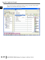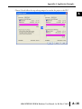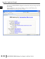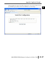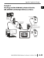
1
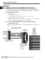
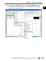
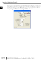
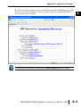
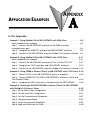
APPLICATION EXAMPLES
APPENDIX
A
In This Appendix...
Example 1: Using Modbus Poll to MB-GATEWAY with DL06 Slave . . . . . . . . . . . .A–2
Items needed for this example: . . . . . . . . . . . . . . . . . . . . . . . . . . . . . . . . . . . . . . . .A–2
Step 1: Connect the MB-GATEWAY serial port to the DL06 secondary
communications port. . . . . . . . . . . . . . . . . . . . . . . . . . . . . . . . . . . . . . . . . . . . . . . .A–2
Step 2: Configure the DL06 PLC serial port and MB-GATEWAY serial port. . . . . . . .A–3
Step 3: Connect to the MB-GATEWAY using the Modbus Poll simulator software. .A–7
Example 2: Using Modbus Poll to MB-GATEWAY with CLICK Slave . . . . . . . . . . .A–11
Items needed for this example: . . . . . . . . . . . . . . . . . . . . . . . . . . . . . . . . . . . . . . .A–11
Step 1: Connect the MB-GATEWAY serial port to Port 3 of the CLICK PLC. . . . . .A–11
Step 2: Configure the CLICK serial port and MB-GATEWAY serial port. . . . . . . . . .A–12
Step 3: Connect to the MB-GATEWAY using the Modbus Poll simulator software. A–18
Example 3: Using P3000 as Master (Client) to MB-GATEWAY with CLICK Slave. A–24
Step 1: Connect CLICK to the MB-GATEWAY as shown in example 2. . . . . . . . . .A–24
Step 2: Connect P3000 CPU (P3-550) to MB-GATEWAY via Ethernet Switch and
Two Ethernet Cables. . . . . . . . . . . . . . . . . . . . . . . . . . . . . . . . . . . . . . . . . . . . . . . .A–24
Step 3: Configure the MRX instruction to read data from the MB-GATEWAY. . . . .A–28
Example 4: DirectLogic 06 (H0-ECOM100) as Master (Client) to MB-GATEWAY
with Mulitple GS Drives as Slaves. . . . . . . . . . . . . . . . . . . . . . . . . . . . . . . . . . . . . .A–29
Step 1: Set up Peer to Peer Configuration . . . . . . . . . . . . . . . . . . . . . . . . . . . . . . .A–30
Step 2: Set the Serial Port Configuration . . . . . . . . . . . . . . . . . . . . . . . . . . . . . . . .A–31
Step 3: Set the Communication Parameters . . . . . . . . . . . . . . . . . . . . . . . . . . . . .A–31
Step 4: Using Automatic Reads . . . . . . . . . . . . . . . . . . . . . . . . . . . . . . . . . . . . . . .A–32
Step 5: Access the Automatic Read Data . . . . . . . . . . . . . . . . . . . . . . . . . . . . . . . .A–33
Step 6: Read and Write from the DL06 . . . . . . . . . . . . . . . . . . . . . . . . . . . . . . . . .A–36
Appendix A: Application Examples
Example 1:
A Using Modbus Poll to MB-GATEWAY with DL06 Slave
This example will illustrate how to use Modbus Poll, which is a PC based Modbus Master
simulator tool, to connect through the MB-GATEWAY to a DL06 PLC via 2 wire RS-485.
Items needed for this example:
• MB-GATEWAY
• DirectLogic 06 PLC (any model)
• PC with Modbus Poll installed (free demo is available at www.modbustools.com)
• Small length of Belden 9842 or equivalent cable
• ZL-CMA15 ZipLink communication port adapter, 15-pin high density female to terminal block
• Ethernet switch and cables to connect from the PC to MB-GATEWAY
Step 1: Connect the MB-GATEWAY serial port to the DL06 secondary
communications port.
Using the short length of Belden 9842, connect the MB-GATEWAY to the DL06 Port 2 as
shown:
RS-422/RS-485
Gateway
Internally Connected
2
3
4
5
6
7
8
9
10
11
12
13
14
A
B
C
D
A–2
GND
RX+
RXTXTX+
GND
(Gateway contains a
120Ω Termination Resistor
between RX+ and RX-)
1
ZL-CMA15
to DL06 Port2
TX+
RX+
TXRXGND
5
10
11
15
15-pin Female
D Connector
DL06 Port 2 Pin Descriptions
1
2
3
4
5
6
7
8
NOTE: If using a connector 9
10
other than ZL-CM15 or
ZL-CMA15L, jumpers must 11
12
be installed on the
13
PLC side:
14
Pin 11 to 14
15
Pin 12 to 15
6
5V Power (+) connection
TXD Transmit data (RS-232C)
RXD Receive data (RS-232C)
RTS Ready to send (RS-232C)
CTS Clear to send (RS-232C)
RXD Recieve data (-) (RS-422/485)
0V Power (-) connection (GND)
0V Power (-) connection (GND)
TXD+ Transmit data (+) (RS-422/485)
TXD- Transmit data (-) (RS-422/485)
RTS+ Ready to send (+) (RS-422/485)
RTS- Ready to send (-) (RS-422/485)
RXD+ Recieve data (+) (RS-422/485)
CTS+ Clear to send (+) (RS-422/485)
CTS- Clear to send (-) (RS-422/485)
MB-GATEWAY-USER-M Hardware User Manual, 1st Ed. Rev. C 10/13
Appendix A: Application Examples
Step 2: Configure the DL06 PLC serial port and MB-GATEWAY serial port.
Connect to the DL06 PLC with DirectSoft. Go to the PLC pulldown and select Setup >
Setup Secondary Comm. Port as shown:
MB-GATEWAY-USER-M Hardware User Manual, 1st Ed. Rev. C 10/13
A
2
3
4
5
6
7
8
9
10
11
12
13
14
A
B
C
D
A–3
Appendix A: Application Examples
A
2
3
4
5
6
7
8
9
10
11
12
13
14
A
B
C
D
A–4
Setup the port as shown for Modbus protocol, 38400 baud rate, Odd parity, 1 Stop bit and
Station Number 1. Match everything else as shown. Note the Station Number configured in
the PLC. Once this has been done, click on the icon on the upper right hand side with the
arrow pointing to the PLC to save the settings in the PLC.
MB-GATEWAY-USER-M Hardware User Manual, 1st Ed. Rev. C 10/13
Appendix A: Application Examples
In order to match the serial port settings of the DL06 to the MB-GATEWAY open up a web
browser, such as Internet Explorer, and enter in the IP address of the MB-GATEWAY to
access the main screen as shown:
For instructions on connecting with a web browser see NetEdit Configuration section in Chapter 3.
MB-GATEWAY-USER-M Hardware User Manual, 1st Ed. Rev. C 10/13
A
2
3
4
5
6
7
8
9
10
11
12
13
14
A
B
C
D
A–5
Appendix A: Application Examples
A
2
3
4
5
6
7
8
9
10
11
12
13
14
A
B
C
D
A–6
Click on the link to the right of “Serial Port Configuration” and set up the window to match
the DL06 PLC port and then click on the Send button to save the settings:
MB-GATEWAY-USER-M Hardware User Manual, 1st Ed. Rev. C 10/13
Appendix A: Application Examples
Step 3: Connect to the MB-GATEWAY using the Modbus Poll simulator
software.
Once the software has been obtained from www.modbustools.com and installed according to
the directions provided from their website, open up the Modbus Poll software.
Click on the Setup pulldown menu and select Read/Write Definition as shown:
MB-GATEWAY-USER-M Hardware User Manual, 1st Ed. Rev. C 10/13
A
2
3
4
5
6
7
8
9
10
11
12
13
14
A
B
C
D
A–7
Appendix A: Application Examples
A
2
3
4
5
6
7
8
9
10
11
12
13
14
A
B
C
D
A–8
Configure the Read/Write definition for a simple read of the register 400001, which equates
to V0 in the DirectLogic PLCs.
(see http://support.automationdirect.com/docs/Modbus_xref.pdf for more information on
Modbus addressing to DirectLogic PLC addressing equivalents).
Enter in 1 for the Slave ID. This matches the Unit ID in the protocol that will determine which Modbus
Serial Slave will be targeted on the serial side of the MB-GATEWAY. Entering 1 here will match up to the
Station Number configured above in DirectSoft for the DL06 PLC.
Choosing Function 3 sets up the read for 4xxxxx registers. Checking the “PLC Addresses (Base 1)” in the
lower right corner matches the addressing to the cross reference chart mentioned above. Once this
windows has been configured as shown above, click on OK.
Now click on the Connection pulldown menu and select Connect:
MB-GATEWAY-USER-M Hardware User Manual, 1st Ed. Rev. C 10/13
Appendix A: Application Examples
In the Connection Setup window, choose the Modbus TCP/IP connection type. Enter the IP
address of your MB-GATEWAY module in the lower left hand corner. Match everything else
as shown:
Click on OK to connect to the MB-GATEWAY.
If everything has been configured correctly, the counter next to “TX =” will increment rapidly
and the counter next to “Err =” will not increment. If the Error counter is incrementing, go
back and verify that all the steps prior to this one have been followed. If you get an error that
says, “Modbus TCP connection failed”, verify that the IP address of the PC and the IP
address of the GATEWAY are in compatible subnets and can communicate.
MB-GATEWAY-USER-M Hardware User Manual, 1st Ed. Rev. C 10/13
A
2
3
4
5
6
7
8
9
10
11
12
13
14
A
B
C
D
A–9
Appendix A: Application Examples
A
2
3
4
5
6
7
8
9
10
11
12
13
14
A
B
C
D
A–10
Once Modbus Poll is communicating to the PLC, go into DirectSoft, open up a Data View
window and enter in V0 and change the display type to “Decimal” to match the Modbus Poll
software:
Change the value in data view for V0 to various values and watch the value change in
Modbus Poll to match.
MB-GATEWAY-USER-M Hardware User Manual, 1st Ed. Rev. C 10/13
Appendix A: Application Examples
Example 2:
Using Modbus Poll to MB-GATEWAY with CLICK Slave
This example will illustrate how to use Modbus Poll, which is a PC based Modbus Master
simulator tool, to connect through the MB-GATEWAY to a CLICK PLC via 2 wire RS-485.
Items needed for this example:
• MB-GATEWAY
• CLICK PLC (any C0-01xx-x or C0-02xx-x PLC with 3 pin terminal RS-485 port)
• PC with Modbus Poll installed (free demo is available at www.modbustools.com)
• Small length of Belden 9842 or equivalent cable
• Ethernet switch and cables to connect from the PC to MB-GATEWAY
Step 1: Connect the MB-GATEWAY serial port to Port 3 of the CLICK PLC.
Using the short length of Belden 9842, connect the MB-GATEWAY to CLICK’s Port 3 as
shown:
Internally Connected
Gateway
GND
RX+
RXTXTX+
GND
RS-485
Port 3
3 Pin
Terminal Block
+
LG
Port 3 Pin Descriptions
+
1 (plus) Signal A (RS-485)
2 (minus) Signal B (RS-485)
3
LG
Logic Ground (0V)
(Gateway contains a
120Ω Termination Resistor
between RX+ and RX-)
MB-GATEWAY-USER-M Hardware User Manual, 1st Ed. Rev. C 10/13
A
2
3
4
5
6
7
8
9
10
11
12
13
14
A
B
C
D
A–11
Appendix A: Application Examples
Step 2: Configure the CLICK serial port and MB-GATEWAY serial port.
A
2
3
4
5
6
7
8
9
10
11
12
13
14
A
B
C
D
A–12
Connect to the CLICK PLC with CLICK programming software. Go to the Setup pulldown
and select Com Port Setup... as shown:
MB-GATEWAY-USER-M Hardware User Manual, 1st Ed. Rev. C 10/13
Appendix A: Application Examples
Click the Port 3: Setup... button to configure Port 3 of the PLC.
Configure the port for 38400 baud rate, Odd parity, 1 Stop Bit and Node Address 1. Leave
the other settings as shown below. Note the Node Address number configured here. Once the
settings are configured, Click on the Ok button.
MB-GATEWAY-USER-M Hardware User Manual, 1st Ed. Rev. C 10/13
A
2
3
4
5
6
7
8
9
10
11
12
13
14
A
B
C
D
A–13
Appendix A: Application Examples
A
2
3
4
5
6
7
8
9
10
11
12
13
14
A
B
C
D
A–14
Next, transfer the project to the PLC for the Port 3 settings to take effect. Select the PLC
pulldown menu and choose Write Project into PLC...
MB-GATEWAY-USER-M Hardware User Manual, 1st Ed. Rev. C 10/13
Appendix A: Application Examples
Choose Ok and follow the steps when prompted to transfer the project to the PLC.
A
2
3
4
5
6
7
8
9
10
11
12
13
14
A
B
C
D
MB-GATEWAY-USER-M Hardware User Manual, 1st Ed. Rev. C 10/13
A–15
Appendix A: Application Examples
A
2
3
4
5
6
7
8
9
10
11
12
13
14
A
B
C
D
A–16
Now go into the MB-GATEWAY configuration and match the serial port settings to the PLC
Port 3 settings.
Open up a web browser, such as Internet Explorer, and enter in the IP address of the
MB-GATEWAY to access the main screen as shown.
MB-GATEWAY-USER-M Hardware User Manual, 1st Ed. Rev. C 10/13
Appendix A: Application Examples
Click on the link to the right of “Serial Port Configuration” and set up the window to match
the CLICK PLC port and then click on the Send button to save the settings:
MB-GATEWAY-USER-M Hardware User Manual, 1st Ed. Rev. C 10/13
A
2
3
4
5
6
7
8
9
10
11
12
13
14
A
B
C
D
A–17
Appendix A: Application Examples
A
2
3
4
5
6
7
8
9
10
11
12
13
14
A
B
C
D
A–18
Step 3: Connect to the MB-GATEWAY using the Modbus Poll simulator
software.
Once the software has been obtained from www.modbustools.com and installed according to
the directions provided from their website, open up the Modbus Poll software.
Click on the Setup pulldown menu and select Read/Write Definition as shown:
MB-GATEWAY-USER-M Hardware User Manual, 1st Ed. Rev. C 10/13
Appendix A: Application Examples
Configure the Read/Write definition for a simple read of the register 400001, which equates
to DS1 in the CLICK PLC as shown.
MB-GATEWAY-USER-M Hardware User Manual, 1st Ed. Rev. C 10/13
A
2
3
4
5
6
7
8
9
10
11
12
13
14
A
B
C
D
A–19
Appendix A: Application Examples
A
2
3
4
5
6
7
8
9
10
11
12
13
14
A
B
C
D
A–20
MB-GATEWAY-USER-M Hardware User Manual, 1st Ed. Rev. C 10/13
Appendix A: Application Examples
Enter in 1 for the Slave ID. This matches the Unit ID in the protocol that will determine which Modbus
Serial Slave will be targeted on the serial side of the MB-GATEWAY. Entering 1 here will match up to the
Node Address configured above in the CLICK programming software for Port 3.
Enter in 1 for the Slave ID. This matches the Unit ID in the protocol that will determine which Modbus
Serial Slave will be targeted on the serial side of the MB-GATEWAY. Entering 1 here will match up to the
Station Number configured above in the CLICK software.
Choosing Function 3 sets up the read for 4xxxxx registers. Checking the “PLC Addresses (Base 1)” in the
lower right corner matches the addressing to the cross reference chart mentioned above. Once this
windows has been configured as shown above, click on OK.
Now click on the Connection pulldown menu and select Connect:
MB-GATEWAY-USER-M Hardware User Manual, 1st Ed. Rev. C 10/13
A
2
3
4
5
6
7
8
9
10
11
12
13
14
A
B
C
D
A–21
Appendix A: Application Examples
A
2
3
4
5
6
7
8
9
10
11
12
13
14
A
B
C
D
A–22
In the Connection Setup window, choose the Modbus TCP/IP connection type. Enter the IP
address of your MB-GATEWAY module in the lower left hand corner. Match everything else
as shown:
Click on OK to connect to the MB-GATEWAY.
If everything has been configured correctly, the counter next to “TX =” will increment rapidly
and the counter next to “Err =” will not increment. If the Error counter is incrementing, go
back and verify that all the steps prior to this one have been followed. If you get an error that
says, “Modbus TCP connection failed”, verify that the IP address of the PC and the IP
address of the GATEWAY are in compatible subnets and can communicate.
MB-GATEWAY-USER-M Hardware User Manual, 1st Ed. Rev. C 10/13
Appendix A: Application Examples
Once Modbus Poll is communicating to the PLC, go into the CLICK programming software,
open up a Data View window and enter in DS1 as shown.
Change the value in data view for DS1 to various values and watch the value change in
Modbus Poll to match.
MB-GATEWAY-USER-M Hardware User Manual, 1st Ed. Rev. C 10/13
A
2
3
4
5
6
7
8
9
10
11
12
13
14
A
B
C
D
A–23
Appendix A: Application Examples
Example 3:
A Using P3000 as Master (Client) to MB-GATEWAY with CLICK
2 Slave.
3
4
5
6
7
8
9
10
11
12
13
14
A
B
C
D
A–24
Step 1: Connect CLICK to the MB-GATEWAY as shown in example 2.
Step 2: Connect P3000 CPU (P3-550) to MB-GATEWAY via Ethernet Switch
and Two Ethernet Cables.
Configure the IP address of the P3 CPU and the MB-GATEWAY to be compatible subnets.
Steps to configure the IP address of the P3-550 CPU areas follows:
Click on Setup on the top menu bar and choose “Hardware Configuration”.
MB-GATEWAY-USER-M Hardware User Manual, 1st Ed. Rev. C 10/13
Appendix A: Application Examples
Double click on the image of the P3-550 in the center of the hardware configuration.
A
2
3
4
5
6
7
8
9
10
11
12
13
14
A
B
C
D
MB-GATEWAY-USER-M Hardware User Manual, 1st Ed. Rev. C 10/13
A–25
Appendix A: Application Examples
A
2
3
4
5
6
7
8
9
10
11
12
13
14
A
B
C
D
A–26
Click on the “Ethernet Ports” tab and configure the IP address in the “Use the Following:” IP
address field. Once the correct IP address and Subnet Mask is entered, click on the OK
button and close the hardware configuration window.
MB-GATEWAY-USER-M Hardware User Manual, 1st Ed. Rev. C 10/13
Appendix A: Application Examples
Transfer the project to the PAC in order to have the new settings take effect. To do this,
select File from the pulldown menu and then Transfer Project >To PAC…
MB-GATEWAY-USER-M Hardware User Manual, 1st Ed. Rev. C 10/13
A
2
3
4
5
6
7
8
9
10
11
12
13
14
A
B
C
D
A–27
Appendix A: Application Examples
Step 3: Configure the MRX instruction to read data from the MB-GATEWAY.
A
2
3
4
5
6
7
8
9
10
11
12
13
14
A
B
C
D
A–28
Double click on the instruction MRX Read to configure the MRX instruction as shown.
IP Address: address of the GATEWAY.
TCP Port Number: Leave at default 502.
Slave Node Number: This should match the Node address of Port 3 of the CLICK PLC.
Leave at 1 in this case.
Slave Modbus Starting Address: Set to 1 to read address DS1 in the CLICK PLC.
Tag Name Mapping: Create a Tag called CLICK_DS1 as an Signed Int 16 Tag to read in
DS1 from the CLICK PLC.
Use the status bits and Exception Response String to verify whether communications were
successful or not. If the Error bit comes on, look at the Exception Response String to see
which error occurred. If the Timeout Bit comes on, check the IP address settings of the P3550 and the GATEWAY and make sure that they are in compatible subnets.
If the Successful Status bit comes on, add the CLICK_DS1 tag to the Data View at the
bottom of the Productivity Suite Programming Software and check the values. Change the
values in the CLICK data view for DS1 and verify that the CLICK_DS1 tag matches.
MB-GATEWAY-USER-M Hardware User Manual, 1st Ed. Rev. C 10/13
Appendix A: Application Examples
Example 4:
DirectLogic 06 (H0-ECOM100) as Master (Client) to
MB-GATEWAY with Mulitple GS Drives as Slaves.
Cable end marked
“Drive Side”
DirectLOGIC
DL06 PLC
w/ ECOM100
10.11.0.221
Ethernet Cat5e
Stride Ethernet
Switch
MB-GATEWAY
10.11.0.233
Unit ID 1
GS Drive
Node ID 2
ZL-CDM-RJ12X4
RS-485
GS-RJ12-CBL-2*
Ethernet
Cat5e
*Caution - Wire ONLY the pins connected by
the cable. The drives DC power available at
the RJ12 pins will affect other drives if other
pins are connected.
RS-485 Cable
PC
10.11.0.10
ZL-CDM-RJ12X4
6-Pin
MB-GATEWAY
6-Pin
GND
RX+
1
2
RX–
3
TX–
4
TX+
GND
shield
5
6
Cable end
marked
“Drive Side”
GS Drive
Node ID 3
MB-GATEWAY-USER-M Hardware User Manual, 1st Ed. Rev. C 10/13
A
2
3
4
5
6
7
8
9
10
11
12
13
14
A
B
C
D
A–29
Appendix A: Application Examples
Step 1: Set up Peer to Peer Configuration
A
2
3
4
5
6
7
8
9
10
11
12
13
14
A
B
C
D
A–30
In NetEdit, Scan Network to find your H0-ECOM100.
Set the Module ID, IP address and Subnet Mask as appropriate for your network. In our
example, we use 7, 10.11.0.221 and 255.255.255.0 respectively.
In the ECOM Settings tab, click the Peer to Peer Config button. Add the Devices appropriate
for your project.
In our example we have added three devices that are the MB-GATEWAY:
Device 1 is the Automatic Reads table that resides in the MB-GATEWAY, so it is configured
with the MB-GATEWAY IP address and the MB-GAEWAY Unit ID.
Device 2 is the first drive. It is configured with the MB-GATEWAY IP address and the first
drive Unit ID.
Device 3 is the second drive. It is configured with the MB-GATEWAY IP address and the
second drive Unit ID.
MB-GATEWAY-USER-M Hardware User Manual, 1st Ed. Rev. C 10/13
Appendix A: Application Examples
Step 2: Set the Serial Port Configuration
In the NetEdit Module List, select your MB-GATEWAY. Set the IP address and subnet mask
as appropriate for your network. In our example, we use 10.11.0.233 and 255.255.255.0.
Click Start Web Based Config... To set the Gateway Modbus ID as appropriate for your
network. In our example, we use 1.
Set the Serial Port Configuration as appropriate for your network. For our example, we use:
Baud rate = 19200
Parity = Odd
Stop bit = 1
Step 3: Set the Communication Parameters
Set the communication parameters in the drives as appropriate for your network.
In our example:
Parameter
Number
Parameter
Description
First Drive
Second Drive
Drive ID
02
03
P9.01
Baud Rate
02
02
P9.02
Modbus RTU, 8-Odd-1
05
05
P3.00
RS-485 interface,
Keypad STOP disabled
Frequency determined by
RS-485 interface
04
04
05
05
P9.00
P4.00
MB-GATEWAY-USER-M Hardware User Manual, 1st Ed. Rev. C 10/13
A
2
3
4
5
6
7
8
9
10
11
12
13
14
A
B
C
D
A–31
Appendix A: Application Examples
Step 4: Using Automatic Reads
A
2
3
4
5
6
7
8
9
10
11
12
13
14
A
B
C
D
A–32
In the MB-GATEWAY browser configuration utility, click the Automatic Reads link. Slave
number 2 is the first drive and Slave number 3 is the second drive in our example. Configure
the lines as appropriate.
For our example, we will read the status registers for each drive:
MB-GATEWAY-USER-M Hardware User Manual, 1st Ed. Rev. C 10/13
Appendix A: Application Examples
Step 5: Access the Automatic Read Data
The ECRX iBox is used since the data will be read by the ECOM100, rather than a serial
connection
MB-GATEWAY-USER-M Hardware User Manual, 1st Ed. Rev. C 10/13
A
2
3
4
5
6
7
8
9
10
11
12
13
14
A
B
C
D
A–33
Appendix A: Application Examples
A
2
3
4
5
6
7
8
9
10
11
12
13
14
A
B
C
D
A–34
ECOM100# = defined for this DL program in the ECOM100 iBox in our Rung 1
Workspace = an internal, private register used by this iBox and MUST BE UNIQUE in this
one instruction and MUST NOT be used anywhere else in your program.
Slave ID = The MB-GATEWAY Modbus Gateway ID, 1, since we are reading the Automatic
Read data stored in the MB-GATEWAY
From Slave Element (Src) = the Gateway Memory Address identified on the MB-GATEWAY
Setup Automatic Reads config page. Note that the address in the MB-GATEWAY, “0” should
be entered here as “V0” and DirectSoft software will change the name to TA0. This is a
naming convention for addresses internal to the PLC and will not affect either the targeted
MB-GATEWAY-USER-M Hardware User Manual, 1st Ed. Rev. C 10/13
Appendix A: Application Examples
address or the use of Timer 0 in the DL program.
Number of Bytes = 20. Since our addresses for both example drives are contiguous, we can
read all 10 elements with one iBox. Each element is a word, 2 bytes, so we want to read 20
bytes to get all 10 elements.
To Master Element (Dest) = the location where the slave data will be placed in the master
ECOM100 PLC
Success = a bit that will turn on once the request is completed successfully
Error = a bit that will turn on if the instruction is not successfully completed
MB-GATEWAY-USER-M Hardware User Manual, 1st Ed. Rev. C 10/13
A
2
3
4
5
6
7
8
9
10
11
12
13
14
A
B
C
D
A–35
Appendix A: Application Examples
Step 6: Read and Write from the DL06
A
2
3
4
5
6
7
8
9
10
11
12
13
14
A
B
C
D
A–36
To Read data from a drive instead of using of the Automatic Read feature of the MBGATEWAY, and to Write data to the drive, the Slave ID in the ECRX and/or ECWX iBoxes
will be the Drive ID. The From Slave Element and/or To Slave Element values will be the
addresses in the drive
continued
MB-GATEWAY-USER-M Hardware User Manual, 1st Ed. Rev. C 10/13
Appendix A: Application Examples
A
2
3
4
5
6
7
8
9
10
11
12
13
14
A
B
C
D
MB-GATEWAY-USER-M Hardware User Manual, 1st Ed. Rev. C 10/13
A–37
Appendix A: Application Examples
A
2
3
4
5
6
7
8
9
10
11
12
13
14
A
B
C
D
A–38
In our example ECRX boxes:
ECOM100# = defined for this DL program in the ECOM100 iBox in our Rung 1.
Workspace = an internal, private register used by this iBox and MUST BE UNIQUE in this
one instruction and MUST NOT be used anywhere else in your program.
Slave ID = The GS Drive Node ID, 2 or 3, depending on which drive we target
From Slave Element (Src) = V20400 equates to Status Monitor 1 in the GS Drive (Hex 2100
and Modbus Decimal 48449). See GS Drive manual for details.
Number of Bytes = Each Modbus register (element) that we want to read is a word, 2 bytes;
in our example we will read 3 status registers.
To Master Element (Dest) = the location where the slave data will be placed in the master
ECOM100 PLC
Success = a bit that will turn on once the request is completed successfully
Error = a bit that will turn on if the instruction is not successfully completed
In our example ECWX boxes:
ECOM100# = Module ID, set in NetEdit and defined for the DL program in the
ECOM100 iBox in our Rung 1
Workspace = an internal, private register used by this iBox and MUST BE UNIQUE in this
one instruction and MUST NOT be used anywhere else in your program.
Slave ID = The GS Drive Node ID, 2 or 3, depending on which drive we target
From Master Element (Src) = the location of data in the Master PLC that will be written to
the drive
MB-GATEWAY-USER-M Hardware User Manual, 1st Ed. Rev. C 10/13
Appendix A: Application Examples
Number of Bytes = 4. In our example, we will write the speed (2 bytes) to the Comm Speed
Reference register and set the next register to RUN (2 bytes)
To Slave Element (Dest) = the Modbus register where the data will be written in the drive.
In this case, V4432 equates to P9.26 Comm Speed Reference. See GS Drive manual for
more details.
Success = a bit that will turn on once the instruction is completed successfully
Error = a bit that will turn on if the instruction is not successfully completed
MB-GATEWAY-USER-M Hardware User Manual, 1st Ed. Rev. C 10/13
A
2
3
4
5
6
7
8
9
10
11
12
13
14
A
B
C
D
A–39