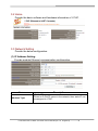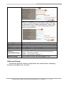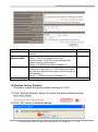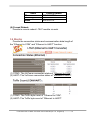
1
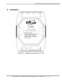
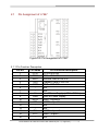
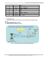
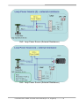
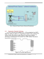
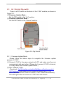
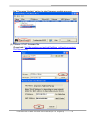
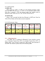
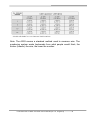
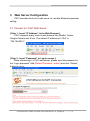
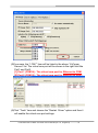
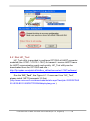
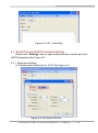
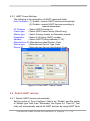
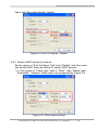
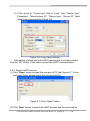
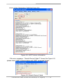
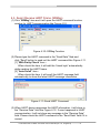
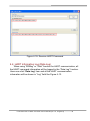
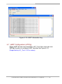
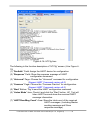
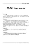
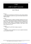
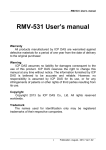
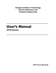
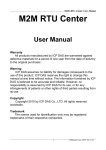
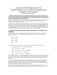
I-7547 Ethernet To HART Converter User’s Manual Warranty All products manufactured by ICP DAS are under warranty regarding defective materials for a period of one year from the date of delivery to the original purchaser. Warning ICP DAS assumes no liability for damages resulting from the use of this product. ICP DAS reserves the right to change this manual at any time without notice. The information furnished by ICP DAS is believed to be accurate and reliable. However, no responsibility is assumed by ICP DAS for its use, or for any infringements of patents or other rights of third parties resulting from its use. Copyright Copyright 2013 by ICP DAS. All rights are reserved. Trademark The names used for identification only may be registered trademarks of their respective companies. I-7547 Ethernet to HART Converter User’s Manual (Ver 1.0, Aug/2013) ------------- 1 Table of Contents 1. Introduction .......................................................................................4 1.1 1.2 Features ............................................................................................. 4 Specifications ..................................................................................... 5 2. Hardware ...........................................................................................7 2.1 2.1.1 2.1.2 2.2 2.3 2.3.1 2.3.2 2.4 2.4.1 2.4.2 2.5 Pin Assignment of I-7547 ................................................................... 8 Pin Function Description .................................................................. 8 HART Wiring .................................................................................... 9 Terminator Resistor Settings ............................................................. 11 Init / Normal Dip-switch .................................................................... 12 Firmware Update Mode .................................................................. 12 Firmware Operation Mode.............................................................. 14 LED Indication .................................................................................. 14 LED Function ................................................................................. 15 LED Indication Table ...................................................................... 15 Cable Selection ................................................................................ 15 3. Web Server Configuration ..............................................................17 3.1 3.2 3.3 3.4 3.5 3.6 Connect to I-7547 Web Server ......................................................... 17 Home ............................................................................................... 18 Network Setting ................................................................................ 18 Monitor ............................................................................................. 21 Change Password ............................................................................ 22 Logout .............................................................................................. 22 4. HC_Tool Utility ................................................................................23 4.1 4.2 VxComm Utility ................................................................................ 23 Run HC_Tool.................................................................................... 25 4.3 4.5 4.6 Serial Port and HART Command Settings ....................................... 26 Serial port settings ......................................................................... 26 HART Frame Settings .................................................................... 27 Search HART devices ...................................................................... 27 Search HART devices automatically .............................................. 27 Search HART devices by manual................................................... 28 Search HART devices .................................................................... 29 Send / Receive HART Frame (SRMsg) ............................................ 31 HART Information Log (Data Log) .................................................... 32 4.7 4.8 HART Configuration (HTCfg) ........................................................... 33 Module Configuration (ModCfg) ....................................................... 35 4.3.1 4.3.2 4.4 4.4.1 4.4.2 4.4.3 I-7547 Ethernet to HART Converter User’s Manual (Ver 1.0, Aug/2013) ------------- 2 5. History Version ................................................................................38 I-7547 Ethernet to HART Converter User’s Manual (Ver 1.0, Aug/2013) ------------- 3 1. Introduction I-7547 is an Ethernet to HART converter designed as the master device of HART protocol. It allows users to access the HART slave via Ethernet by using virtual COM port. These HART slave devices may be a transmitter, actuator, current output device and so forth. I-7547 provides four HART channels and built-in 250 Ω load resistor in each HART channel adjustable by jumper. In addition, we also provide free utility tool (HC_Tool) for users to configure I-7547 and test HART communication easily and quickly. The following is the application structure of I-7547. 1.1 Features Support HART Short / Long frame. Support HART Burst mode. Support point-to-point or multi-drop HART mode. Support connecting up to 15 HART slave devices. Allow two HART masters. Provide utility tool for module configuration and HART communication. I-7547 Ethernet to HART Converter User’s Manual (Ver 1.0, Aug/2013) ------------- 4 Provide four HART channels. Support firmware update via Ethernet Provide PWR / TxRx indication LED 4KV ESD Protection Built-in Watchdog Selectable 250Ω load resistor for each HART channel. 1.2 Specifications [ Ethernet Spec. ] Ethernet Port Virtual COM Built-In Web Server [ HART Spec. ] Channel Connector Device type Network Comm. Mode Frame Burst Mode Max. Device Load Resistor Isolation Operate Mode 10/100 Base-TX with Auto MDI/MDI-X Created by VxComm Utility Ethernet Parameters Configuration 4 2-pin screwed terminal block (for each HART Ch.) Two-wiring or four-wiring HART devices Point to Point or Multi-drop Only HART digital communication Short or Long frame Support 15 HART slave devices Selectable 250Ω by Jumper (for each HART Ch.) 500 VDC HART Master and supports all HART commands [ COM Spec. ] COM1 Tx / Rx / GND / RTS / CTS Baud Rate (bps) 1200 ~ 115200bps Data Format N/O/E (parity), 5/6/7/8 (data bit), 1/2 (stop bit) [ Power Requirement ] Power supply Unregulated +10 ~ +30 VDC I-7547 Ethernet to HART Converter User’s Manual (Ver 1.0, Aug/2013) ------------- 5 Protection Power reverse protection, Over-Voltage brown-out protection Power Consumption 1.5W [ Module spec. ] Dimensions Operating temperature Storage temperature Humidity LED 123mm x 72mm x 35mm (H x W x D) -25 ~ +75 ℃ (-13 to 167 ℉) -30 ~ +80 ℃ (-22 to 176 ℉) 5% ~ 95% RH, non-condensing PWR : Power Indicator TxRx : Data Received from Ethernet / HART Indicator [ Utility Tool ] Provide module configuration and HART communication easily and quickly. Provide HART devices search automatically. Provide diagnostic Information of HART device. Provide data logging for HART communication. [ Application ] Current Measuring. Petrochemical Industry Application. Environment Monitoring. Tunnel Monitoring. Monitor system. Building Monitoring. I-7547 Ethernet to HART Converter User’s Manual (Ver 1.0, Aug/2013) ------------- 6 2. Hardware Figure 2-1: Hardware externals of I-7547 I-7547 Ethernet to HART Converter User’s Manual (Ver 1.0, Aug/2013) ------------- 7 2.1 Pin Assignment of I-7547 Figure 2-3: Pin Assignment of I-7547 2.1.1 Pin Function Description Pin No. Pin Name 1 CTS1 2 RTS1 3 RxD1 4 TxD1 5 GND 6 7 8 +Vs 9 GND 10 HT0+ 11 HT012 13 14 HT1+ 15 HT116 - Pin Function Description CTS of RS-232 RTS of RS-232 Receive Data of RS-232 Transmit Data of RS-232 GND of RS-232 N/A N/A V+ of Power Supply (+10V~+30Vdc) GND of Power Supply HART+ of port 0 HART- of port 0 N/A N/A HART+ of port 1 HART- of port 1 N/A I-7547 Ethernet to HART Converter User’s Manual (Ver 1.0, Aug/2013) ------------- 8 17 18 19 20 21 22 23 E1 HT2+ HT2HT3+ HT3Ethernet N/A HART+ of port 2 HART- of port 2 N/A N/A HART+ of port 3 HART- of port 3 10 / 100M 2.1.2 HART Wiring The HART network connection can be divided to the following two types. (1) ”Loop Power Source” Mode. (2) ”External Power Source” Mode. Ex1 : Loop Power Source (Internal Resistance) I-7547 Ethernet to HART Converter User’s Manual (Ver 1.0, Aug/2013) ------------- 9 Ex2 : Loop Power Source (External Resistance) Ex3 : Loop Power Source (External Resistance) I-7547 Ethernet to HART Converter User’s Manual (Ver 1.0, Aug/2013) ------------- 10 Ex4 : External Power Source (External Resistance) 2.2 Terminator Resistor Settings In I-7547, there are four jumpers (JP3 ~ JP6) provided for four HART channels, shown as Figure 2-4. The jumper can select HART network with 250Ω (1/4 W) load resistor or not. When the pin 1&2 is connected, the resistor will be connected to HART network. When the pin 2&3 is connected, it will disconnect the resistor from HART network. By default, the pin1&2 is connected. Figure 2-4: Internal Load Resistor I-7547 Ethernet to HART Converter User’s Manual (Ver 1.0, Aug/2013) ------------- 11 2.3 Init / Normal Dip-switch There is a DIP switch on the back of the I-7547 module, as shown in Figure 2-5. (1) Firmware Update Mode : Set the DIP switch to the “Init” position. (2) Firmware Operation Mode : Set the DIP switch to the “Normal” position. Figure 2-5: Dip Switch 2.3.1 Firmware Update Mode Please follow the below steps to complete the firmware update process of I-7547. (1) Connect I-7547 to the same network with PC and make sure they can communicate with each other. (Please don’t connect I-7547 to Internet, or it may cause the firmware update failure.) (2) Run “eSearch” Utility. (Download : ftp://ftp.icpdas.com/pub/cd/fieldbus_cd/hart/converter/i7547/software/ and make sure the version is newer than v1.0.8) Click ”Search Servers” button to search I-7547 module automatically. Click the right button of mouse on I-7547 item and choose I-7547 Ethernet to HART Converter User’s Manual (Ver 1.0, Aug/2013) ------------- 12 the ”Firmware Update” option to start firmware update process. (3) Choose I-7547 firmware file. (Download: ftp://ftp.icpdas.com/pub/cd/fieldbus_cd/hart/converter/i7547/firmware/) I-7547 Ethernet to HART Converter User’s Manual (Ver 1.0, Aug/2013) ------------- 13 (4) In DOS command window, it will show the message for ready to update firmware. (5) Set the dip switch to the “Init” position and reboot I-7547. After that, it will start to update firmware automatically. (6) After the process of firmware update finished, set the dip switch to the “Normal” position and reboot I-7547. 2.3.2 Firmware Operation Mode Set the dip switch to the “Normal” position and then reboot I-7547. I7547 will run in operation mode and then users can communicate with HART device via Ethernet. 2.4 LED Indication There are two LEDs provided to indicate what situation the I-7547 is in. The Figure 2-6 is the illustration of these two LEDs. Figure 2-6: LED position of I-7547 I-7547 Ethernet to HART Converter User’s Manual (Ver 1.0, Aug/2013) ------------- 14 2.4.1 LED Function (1) PWR LED : When power on I-7547, if I-7547 is in the firmware operation mode, then the PWR LED will be on. If I-7547 is in the firmware update mode, then after 5 seconds, I-7547 will change mode from update mode to operation mode. When turn off I-7547, the all LEDs will be off. (2) TxRxD LED : When I-7547 received the data from Ethernet or HART port, then the TxRx LED will flash until the data received completed. 2.4.2 LED Indication Table Mode Power LED off Name PWR LED Off TxRx LED Off 2.5 FW Update FW Operation On after 5 sec when reboot Off On immediately when reboot Off Ethernet Data Received HART Port Data Received On On Flash Flash Cable Selection The HART bus is a balanced (differential) 2-wire interface running over a Shielded Twisted Pair (STP), Un-shielded Twisted Pair (UTP), or Ribbon cable. How to decide a cable type, cable length, and terminator in the HART bus network, please refer to the following table. I-7547 Ethernet to HART Converter User’s Manual (Ver 1.0, Aug/2013) ------------- 15 Note: The AWG means a standard method used to measure wire. The numbering system works backwards from what people would think, the thicker (heavier) the wire, the lower the number. I-7547 Ethernet to HART Converter User’s Manual (Ver 1.0, Aug/2013) ------------- 16 3. Web Server Configuration I-7547 provides the built-in web server for module Ethernet parameter setting. 3.1 Connect to I-7547 Web Server [ Step 1: Input “IP Address” in the Web Browser ] I-7547 supports many kinds of web browser like Mozilla, Firefox, Google Chrome and IE etc. The default IP address of I-7547 is “192.168.255.1“. [ Step 2: Input “Password” in Log-In screen ] When connecting to I-7547 web server, please input the password in the “Login password” field (Default Password : admin) and click “Submit” button to log in. I-7547 Ethernet to HART Converter User’s Manual (Ver 1.0, Aug/2013) ------------- 17 3.2 Home Provide the basic software and hardware information of I-7547. 3.3 Network Setting Provide the below configuration. (1) IP Address Setting: Provide module Ethernet communication configuration. Items Address Type Description [ Static IP ] If there is no DHCP server in the network, then static IP can be assigned to I-7547. I-7547 Ethernet to HART Converter User’s Manual (Ver 1.0, Aug/2013) ------------- 18 [ DHCP / AutoIP ] If there is a DHCP server in the network, then I-7547 can be assigned to the IP address automatically. When I-7547 reboots, the IP address of I-7547 assigned by the DHCP server may be different. Static IP Address Subnet Mask Default Gateway MAC Address TCP Command Port Command Port Timeout (Socket Watchdog) Set the static IP address. Set the subnet mask. Set the gateway. Set the user-defined MAC address. Default TCP command port is 10000. If command port doesn’t receive any TCP/IP data within the timeout, then I-7547 will be disconnected automatically. Range : 1~65535 (seconds); Default : 30 (seconds); Disabled = 0 Update Settings Click the button to save the new settings to I-7547. (2) General Setting: Provide the general module configuration like module alias, watchdog and web auto-logout etc. function. I-7547 Ethernet to HART Converter User’s Manual (Ver 1.0, Aug/2013) ------------- 19 Items Alias Name System Timeout (Network WDT) Web Auto-logout Update Settings Description Default Set the module alias for easy identification in the ETH2HART network. Set the system timeout value. 300 (When I-7547 error happened and lost communication, it will reboot automatically after system timeout value passed.) Range : 30~65535 (seconds); Disabled = 0; Set the timeout value for web auto-logout. 10 (If there is no any action in I-7547 web server within the web auto-logout timeout value, then it will log out automatically.) Range : 1~65535 (minutes); Disabled = 0; Click the button to save the new settings to I-7547. (3) Restore Factory Defaults: Provide to restore the factory default settings of I-7547. [1] Click “Restore Defaults” button to restore the factory default settings. [2] Click “OK” button to finish the setting. I-7547 Ethernet to HART Converter User’s Manual (Ver 1.0, Aug/2013) ------------- 20 Items IP Gateway Mask Factory Default 192.168.255.1 192.168.0.1 255.255.0.0 (4) Forced Reboot: Provide to remote reboot I-7547 module via web. 3.4 Monitor Provide the connection status and communication data length of the ”Ethernet to COM” and ”Ethernet to HART” function. (1) COM1: The VxComm connection status of “Ethernet to COM”. (2) HART: The VxComm connection status of “Ethernet to HART”. (1) COM1: The Tx/Rx byte count of “Ethernet to COM”. (2) HART: The Tx/Rx byte count of “Ethernet to HART”. I-7547 Ethernet to HART Converter User’s Manual (Ver 1.0, Aug/2013) ------------- 21 3.5 Change Password Provide the new password setting for web server login. Items Current password New password Confirm new password Submit Description Input the old password. (Default : admin) Input the new password. Input the new password again. Click the button to save the new settings to I-7547. 3.6 Logout When click the “Logout” label, it will logout the web server of I-7547 automatically and connect to the login screen. I-7547 Ethernet to HART Converter User’s Manual (Ver 1.0, Aug/2013) ------------- 22 4. HC_Tool Utility 4.1 VxComm Utility Before using HC_Tool utility to communicate with I-7547, please install the “VxComm Utility” software first to create a virtual com port. (1) Install the “VxComm Utility”. (Download: ftp://ftp.icpdas.com/pub/cd/fieldbus_cd/hart/converter/i7547/software/ and make sure the version is newer than v2.12)。 (2) Run the “VxComm Utility”. Click the ”Search Servers” button to search all I-7547 modules automatically. (3) Click the right button of mouse on the “I-7547” item and choose the ”Add Server(s)” option. (4) In ”COM Port:“ item, choose the com port number. I-7547 Ethernet to HART Converter User’s Manual (Ver 1.0, Aug/2013) ------------- 23 (5)If success, the “I-7547” item will be listed in the above “VxComm Servers” list. The virtual com port will be shown in the right field like Port1 and Port2. [1] Port 1 (COM14) : The virtual com port for Ethernet to COM. [2] Port 2 (COM15) : The virtual com port for Ethernet to HART. (6)Click ”Tools” item and choose the ”Restart Driver” option and then it will enable the virtual com port settings. I-7547 Ethernet to HART Converter User’s Manual (Ver 1.0, Aug/2013) ------------- 24 4.2 Run HC_Tool HC_Tool utility is provided to configure ICP DAS all HART converter modules (like I-7567 / I-7570 / I-7547) or transmit / receive HART frame for HART communication easily and quickly. HC_Tool utility can be downloaded from the ICP DAS web site : http://ftp.icpdas.com/pub/cd/fieldbus_cd/hart/converter/i-7547/software/. Run the “HC_Tool“, like Figure 4-1. If users can’t run “HC_Tool”, please install .NET Framework 3.5 first. (http://www.microsoft.com/downloads/details.aspx?familyid=333325FDAE 52-4E35-B531-508D977D32A6&displaylang=en ). I-7547 Ethernet to HART Converter User’s Manual (Ver 1.0, Aug/2013) ------------- 25 Figure 4-1: HC_Tool Utility 4.3 Serial Port and HART Command Settings Please click “Settings” item to open setting window of serial port and HART parameters like Figure 4-2. 4.3.1 Serial port settings (1) Please select serial port no. of PC like Figure 4-2. Figure 4-2: Set Serial Port No. I-7547 Ethernet to HART Converter User’s Manual (Ver 1.0, Aug/2013) ------------- 26 4.3.2 HART Frame Settings The following is the description of HART command fields. Auto Configure : (1) Enable : search HART devices automatically. (2) Disable : search HART devices according to manual parameters. HT Channel : Select HART channel no. Frame type : Select HART frame format (Short/Long). Master type : Select Primary master or Secondary master. Preambles : Select 5~20 bytes (0xFF) number. Address : Select HART Polling Address (0~15). Manufacturer ID: Manufacturer Identification Code Device type : Manufacturer Device Type Code Device ID : Manufacturer Device Identification Code. Figure 4-3: Set HART Frame Format 4.4 Search HART devices 4.4.1 Search HART devices automatically Set the option of “Auto Configure” field to be “Enable” and the option of “Master type” field to be “Secondary” like Figure 4-4. Then HC_Tool utility will automatically search all HART devices by using HART short I-7547 Ethernet to HART Converter User’s Manual (Ver 1.0, Aug/2013) ------------- 27 frame with “Secondary Master” identity. Figure 4-4: Auto Configure - Enable 4.4.2 Search HART devices by manual Set the option of “Auto Configure” field to be “Disable” and then users can set the HART frame by manual to search HART devices. (1) If the option of “Frame type” field is “Short”, then “Master type”, “Preambles”, “Address” fields need to be configured like Figure 4-5. Figure 4-5: Short frame settings I-7547 Ethernet to HART Converter User’s Manual (Ver 1.0, Aug/2013) ------------- 28 (2) If the option of “Frame type” field is “Long”, then “Master type”, Preambles”, “Manufacturer ID”, “Device type”, “Device ID” fields need to be configured like Figure 4-6. Figure 4-6: Long frame settings If the setting of serial port and HART frame format is finished, please click the “OK” button. Then users can test the HART communication. 4.4.3 Search HART devices (1) Click “Open” button to open the com port of PC like Figure 4-7. If com port open failed, please check the com port setting. Figure 4-7: Click “Open” button (2) Click “Start” button to search all HART devices and the result will be I-7547 Ethernet to HART Converter User’s Manual (Ver 1.0, Aug/2013) ------------- 29 shown in the ”Information” field like Figure 4-8. Figure 4-8: HART device Information If the error message - “Search Device Failed !!” shows like Figure 4-9, please check HART network status and HART command format. Figure 4-9: Search Device Failed I-7547 Ethernet to HART Converter User’s Manual (Ver 1.0, Aug/2013) ------------- 30 4.5 Send / Receive HART Frame (SRMsg) (1) Click “SRMsg” item and it will open the HART command function window for HART communication like Figure 4-10. Figure 4-10: SRMsg Function (2) Please type the HART command in the ”Send Data” filed and click ”Send” button to send out the HART command like Figure 4-11. [1] “With Parity Check” item : When check the item, it will add the “check byte” automatically while sending the HART frame. [2] “Auto Scroll” item : When check the item, it will scroll the HART message field automatically to show the latest HART message information. Figure 4-11: Send HART Command (3) When HART device responses the HART information, it will show in the ”Receive Data” field like Figure 4-12. If error happened in HART communication, it will not show any message in the “Receive Data” field. Please check the HART command in the “Send Data” field if it is correct. I-7547 Ethernet to HART Converter User’s Manual (Ver 1.0, Aug/2013) ------------- 31 Figure 4-12: Receive HART Command 4.6 HART Information Log (Data Log) When using “SRMsg” or “Start” function for HART communication, all the HART command information will be logged in the “Data Log“ function. Users can click “Data Log” item and all the HART communication information will be shown in “Log” field like Figure 4-13. I-7547 Ethernet to HART Converter User’s Manual (Ver 1.0, Aug/2013) ------------- 32 Figure 4-13: HART Information Log 4.7 HART Configuration (HTCfg) When HART devices are searched in HC_Tool, then users can use “HTCfg” function to configure HART devices like Figure 4-14. (Supported by HC_Tool v1.02 or newer) I-7547 Ethernet to HART Converter User’s Manual (Ver 1.0, Aug/2013) ------------- 33 Figure 4-14: HTCfg Item The following is the function description of “HTCfg” screen. (Like Figure 415) (1) “DevAddr” Field: Assign the HART device for configuration. (2) “Response” Field: Show the response message of HART configuration command. (3) “Universal” Page: Choose the “Universal” command for configuration. (Support HART Command version v6.0) (4) “Common” Page: Choose the “Common-Practice” for configuration. (Support HART Command version v6.0) (5) “Start” Button: Trig to send the HART configuration command. (6) “Listen Mode” item: Check it and click the ”Start” button, HC_Tool will listen HART bus and show the received HART message information. (7) “HART RecvMsg Count” Area: Show the total count of the received HART messages. (Including Master sending message and Slave response message) I-7547 Ethernet to HART Converter User’s Manual (Ver 1.0, Aug/2013) ------------- 34 Figure 4-15: HTCfg Screen 4.8 Module Configuration (ModCfg) Click ”ModCfg” item, it will show the below two options to open the module configuration screen of HART Converter like Figure 4-16. (1) HC_Tool : v1.02 or newer supported. (2) I-7567 : FW_v1.5 or newer supported. (3) I-7570 : FW_v1.4 or newer supported I-7547 Ethernet to HART Converter User’s Manual (Ver 1.0, Aug/2013) ------------- 35 Figure 4-16: ModCfg Item The following is the function description of “ModCfg”. 1. “For All” Option : (Like Figure 4-17) Note : It is used for all HART Converter modules Figure 4-17: “For All” Option - Configuration Screen (1) “Get Module FW Version”: => Return the firmware version of HART converter module. (2) “Reset Module”: => Reset HART converter module. (3) “Get HART Send/Recv Count”: => Return the total count of the sending and receiving HART messages in HART converter module. (4) “Reset HART Send/Recv Count”: => Reset the total count of the sending and receiving HART messages in HART converter module. (5) “Set HART Channel”: (Only for I-7547) => Set the HART channel (Range: 0 ~ 3) of I-7547 for HART communication by using ”HART Ch” option. Users can also set the HART channel by send com port command. For example: Send Command => #C52\r (Set HART channel to be 2) I-7547 Ethernet to HART Converter User’s Manual (Ver 1.0, Aug/2013) ------------- 36 Return Data => !C5\r (Success) Return Data => ?02\r (Failure) [Note] 1. Only one HART channel in I-7547 can be used to communicate with HART device in the same time. (6) “Get HART Channel”: (Only for I-7547) => Return the HART channel (Range: 0 ~ 3) of I-7547. Users can also get the HART channel by send com port command. For example: Send Command => #C6\r Return Data => !C6_2\r (The current HART channel is 2.) 2. “For I-7570” Option : (Like Figure 4-18) Note : It is just used to I-7570 module and make sure the I-7570 must run in ”Config Mode” first. Figure 4-18: “For I-7570” Option - Configuration Screen I-7547 Ethernet to HART Converter User’s Manual (Ver 1.0, Aug/2013) ------------- 37 5. History Version Ver. Author Date 1.0 Edward 2013/08/27 Description 1. First version I-7547 Ethernet to HART Converter User’s Manual (Ver 1.0, Aug/2013) ------------- 38